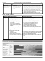
PROPOINT 8958696 Le manuel du propriétaire
- Catégorie
- Système de soudage
- Taper
- Le manuel du propriétaire

V1.2 8958696
Please read and understand all instructions before use. Retain this manual for future reference.
PRO.POINT 105I MIG
GAS/FLUX-CORED WELDER
USER MANUAL

8958696 PRO.POINT 105I MIG GAS/FLUX-CORED WELDER V1.2
2 For technical questions call 1-800-665-8685
Specifications
SPECIFICATIONS
Input Voltage
115VAC
Output Current Range
40 to 105A
Max. Amperage Draw
26.5A
MIG Welding Output @ 20% Duty Cycle
105A
AC/DC Output
DC
No-Load Voltage
46V
Welding Capacity
3/16 in. Mild Steel and Stainless Steel
Wire Feed Speed
Automatic
Welding Wire Diameter
0.023 / 0.030 / 0.035 in.
Welding Wire Type
FCAW: AWS E71T-GS and GMAW: AWS ER70S-6
Welding Gas
Argon, Argon & CO2 mix, or CO2 (requires adapter)
Insulation Class
B
Power Factor
0.74
Dimensions (L x W x H)
14 x 5.2 x 9.85 in.
Generator Compatible
Yes
Weight
13 lb
INTRODUCTION
The Pro.Point 105i MIG Gas/Flux-Cored Welder incorporates the latest in IGBT technology for
maximum efficiency and longer duty cycles. The welding unit has both a gas and gasless option.
The wire feed speed is automatically calibrated based on the wire size and Synergic control
knob settings.
SAFETY
WARNING! Read and understand all instructions before using this tool. The operator must follow
basic precautions to reduce the risk of personal injury and/or damage to the equipment.
Keep this manual for safety warnings, precautions, operating or inspection and maintenance
instructions.
HAZARD DEFINITIONS
Please familiarize yourself with the hazard notices found in this manual. A notice is an alert that
there is a possibility of property damage, injury or death if certain instructions are not followed.
DANGER! This notice indicates an immediate and specific hazard that will result in severe
personal injury or death if the proper precautions are not taken.
WARNING! This notice indicates a specific hazard or unsafe practice that could result in
severe personal injury or death if the proper precautions are not taken.
CAUTION! This notice indicates a potentially hazardous situation that may result in minor or
moderate injury if proper practices are not taken.
PRO.POINT 105I MIG
GAS/FLUX-CORED WELDER

V1.2 PRO.POINT 105I MIG GAS/FLUX-CORED WELDER 8958696
Visit www.princessauto.com for more information 3
NOTICE! This notice indicates that a specific hazard or unsafe practice will result in
equipment or property damage, but not personal injury.
WORK AREA
1. Operate in a safe work environment. Keep your work area clean, well-lit and free of distractions.
2. Remove all unnecessary people from the work area when welding. Anyone remaining in the
work area must wear the appropriate welding safety equipment.
3. Store tools properly in a safe and dry location. Keep tools out of the reach of children.
4. Do not install or use in the presence of flammable gases, dust or liquids.
5. Welding sparks and ejected molten slag can start a fire. Remove combustible materials
within 39 ft (12 metres) of the welding unit. See Fire and Explosion Precautions.
6. Have a fire extinguisher readily available (see Fire and Explosion Precautions).
7. Use protective screens or barriers to protect others from flash and glare; warn others in the
area to look away from the arc.
8. Keep the welding unit at least one foot from any wall or structure.
9. Check that the work area is free from fires, sparks or hot debris before leaving.
PERSONAL SAFETY
WARNING! Wear personal protective equipment approved by the Canadian Standards
Association (CSA) or American National Standards Institute (ANSI).
HEAD PROTECTION
DANGER! Never look directly at the welding arc without the proper protection. The light can
cause flash burn damage and impair vision. Although treatment is possible, multiple
occurrences can result in permanent eye damage.
1. Protect your eyes from welding light by wearing a welder's helmet fitted with a filter shade
suitable for the type of welding you are doing. The welding process produces intense white
light, infrared and ultraviolet light, these arc rays can burn both eyes and skin.
1.1. Consult the Welding Shade Guide in Appendix A for the minimum shade to protect the
eyes based on the amperage and type of welding.
2. An opaque helmet will protect against the ultraviolet or infrared light. A helmet will also
protect against ejected hot material and slag. The helmet should protect the face, forehead,
ears and neck.
3. Wear a fire-resistant head covering like a skull cap or balaclava hood to protect your head
when the faceplate is down or when using a welding hand-held face shield.
4. Wear ventilated safety goggles beneath the welding helmet or behind the hand-held face
shield. The cooling weld bead may fragment or eject slag that can damage the eyes, when
the helmet or hand-held face shield is not in place.
4.1 Eye protection equipment should comply with CSA Z94.3-07 or ANSI Z87.1 standards
based on the type of work performed.
5. Wear fire resistant ear plugs when welding overhead to prevent spatter or slag from falling
into ear.
PROTECTIVE CLOTHING
1. Wear a leather apron or jacket, leather welding gloves and full foot protection. Choose clothing
fabrics that resist sparks, heat, flames and splashes of molten material. Artificial fabrics may
burn and melt, resulting in a more severe injury.
1.1 Wear welding capes and sleeves when performing overhead welding.
2. Do not wear clothes or protective gear that are frayed, oily or greasy as they may ignite
from the heat or ejected slag and sparks.

8958696 PRO.POINT 105I MIG GAS/FLUX-CORED WELDER V1.2
4 For technical questions call 1-800-665-8685
3. Wear thick clothes that do not expose the skin. Ultraviolet or infrared light can burn skin
with sufficient exposure.
4. Do not wear clothing that can hold hot debris or sparks such as pant cuffs, shirt pockets or
boots. Choose clothing that has flaps over pockets or wear clothing to cover the openings
such as pant legs over the boots or an apron over the shirt.
5. Gloves should contain an insulating lining to protect against an electric shock.
6. Rubber soled footwear or electrically insulated work boots are recommended while
working with a welding unit. The non- skid sole is will also help maintain footing and
balance during work.
6.1 Select boots with steel toe protection to prevent injury from falling objects.
RESPIRATORS
1. Respiratory protection is needed when ventilation is not sufficient to remove welding fumes
or when there is risk of oxygen deficiency.
1.1. Wear a NIOSH approved respirator when working on materials that produce dust or
particulate matter.
2. Work in a confined space only if it is well ventilated or while wearing an air-supplied
respirator. Welding fumes and gases can displace air and lower the oxygen level causing
injury or death. Be sure the breathing air is safe (See Fumes and Gases).
3. The user can take the additional precaution of informing another person in the work area of
the potential danger, so that person can watch for indications that the user is suffering from
oxygen deprivation.
PERSONAL PRECAUTIONS
Control the tool, personal movement and the work environment to avoid personal injury or
damage to the tool.
1. Do not operate any tool when tired or under the influence of drugs, alcohol or medications.
2. Avoid wearing clothes or jewelry that can become entangled with the moving parts of a
tool. Keep long hair covered or bound.
3. Remove all jewelry or metal items from your person before welding. Metal items may
connect to the welding unit’s electrical circuit, causing an injury or death.
4. Do not overreach when operating the tool. Proper footing and balance enable better control in
unexpected situations.
5. Support the workpiece or clamp it to a stable platform. Holding the workpiece by hand or
against your body may lead to personal injury.
6. Do not wear any personal grooming products that are flammable, such as hair preparations,
perfume or cologne with an alcohol base.
7. Remove any combustibles, such as butane lighters or matches, from your person before
doing any welding. Hot welding sparks may light the matches or ignite leaking lighter fuel.
SPECIFIC SAFETY PRECAUTIONS
WARNING! DO NOT let comfort or familiarity with product (gained from repeated use)
replace strict adherence to the tool safety rules. If you use this tool unsafely or incorrectly,
you can suffer serious personal injury.
Welding produces sparks, molten slag, intense white light, plus infrared and ultraviolet light. A
cooling bead can eject chips or fragments of slag. Any of these can cause direct harm to the
eyes and skin of the welder or bystanders.
1. Use the correct tool for the job. This tool was designed for a specific function. Do not
modify or alter this tool or use it for an unintended purpose.

V1.2 PRO.POINT 105I MIG GAS/FLUX-CORED WELDER 8958696
Visit www.princessauto.com for more information 5
2. Protect against reflected arc rays. The rays can reflect off a shiny surface behind the user,
into the helmet and off the filter lens into the eyes. Remove or cover any reflective surface
behind the user such as a glossy painted surface, aluminum, stainless steel or glass.
3. Welding produces sparks and molten slag. A cooling bead can eject chips or fragments of
slag. Any of these can cause direct harm to the eyes or skin of the user or bystanders.
4. Erect protective screens or barriers to protect bystanders from the flash and glare; warn
others in the area not to watch the arc. Do not strike a welding arc until all bystanders and
you (the user) have welding shields and/or helmets in place.
5. Immediately replace a cracked or broken helmet or a scratched or damaged lens filter to
avoid damage to the eyes or face from arc flash or ejected molten material.
6. Do not allow the welding torch to accidentally touch the ground clamp or grounded work. An
arc flash will result from contact and can injury the unprepared user and bystanders.
7. Do not handle hot metal or welding wire stubs with bare hands. Handling may result in a burn
injury.
8. Do not use the welding unit if personal movement is confined or if there is a danger of falling.
9. Keep all panels and covers securely in place when operating the welding unit.
10. Insulate the ground clamp when not connected to a workpiece to prevent contact with any
metal object.
11. Do not operate the welding unit if the welding torch or welding cable is wet. Do not
immerse them in water. These components and the welding unit must be completely dry
before attempting to use them.
12. Do not point the welding torch at any body part of yourself or at anyone else.
13. Do not use a welding unit to thaw frozen pipes.
14. Insulate yourself from the work and the ground using dry insulation. Make certain that the
insulation is large enough to cover your full area of physical contact.
15. When not welding, make certain that no part of the welding wire circuit is touching the
workpiece or the ground. Accidental contact can cause overheating and create a fire hazard.
16. Maintain good ventilation of the louvres on this equipment. Good ventilation is of critical
importance for the normal performance and service life of this equipment.
FIRE AND EXPLOSION PRECAUTIONS
Welding can produce sparks, hot slag or spatter, molten metal drops and hot metal parts that
can start fires.
1. Clear the floor and walls of an area of all combustible and/or flammable materials up to
39 ft (12 metres) away from the welding unit. Hot debris ejected during welding can land
at a considerable distance away. Solid floors of concrete or masonry is the preferred
working surface.
1.1 Cover any combustible material with fire resistant covers or shields, if it cannot be
removed. The covering must be tight and should not leave openings for sparks or
ejected slag to enter.
1.2. Check both sides of a panel or wall for combustible material. Remove the combustible
material before welding.
2. A combustible floor should be protected with a fire-resistant covering. Alternatives are to
spray the floor with water to keep it wet for the duration of the welding or cover with damp
sand. Care must also be taken to avoid an electric shock when this is done. A combustible
floor directly laid onto concrete does not need to be sprayed with water.

8958696 PRO.POINT 105I MIG GAS/FLUX-CORED WELDER V1.2
6 For technical questions call 1-800-665-8685
3. Seal cracks and openings to adjacent areas that a spark or slag can enter. Seal any openings
found with a fire-resistant cover. Shut doors and windows that do not provide ventilation or
erect protective screens in front of them when possible.
4. Avoid welding near hydraulic lines or containers containing flammable contents.
5. Do not perform any welding work on containers that held flammable or toxic substance
until they are cleaned by a person trained in removing toxic and flammable substances and
vapours per the American Welding Standard AWS F4.1.
6. Open a container before performing any welding work on it. The heat generated by the
welding process will cause the air and gases to expand. The internal pressure may cause a
sealed or closed container to rupture, possibly causing an injury or death.
7. Do not weld pipes or metal that are covered in combustible material or in contact with
combustible structure such as a wall. Only weld if the covering can be safely removed.
7.1 Follow all safety precautions and legal requirements before welding a workpiece that
contains Asbestos or attempting to remove the Asbestos covering. This requires expert
knowledge and equipment.
7.2 Molten slag can run down the inside and outside of a pipe and start a fire. Be aware
where the pipe terminates and take precautions.
8. Do not weld a panel that is a sandwich construction of combustible and metal materials.
9. Have a fire extinguisher available for immediate use. A dry chemical fire extinguisher for
Types A, B and C is suggested.
9.1 Welding a combustible metal like zinc, magnesium or titanium requires a Type D
fire extinguisher.
9.2 Do not use liquid-based fire extinguishing methods near the electric welding unit, as it
may cause a shock hazard.
10. Ventilation systems should be positioned so sparks or molten slag isn’t carried to an
adjacent area.
11. Have a Fire Watcher observing areas outside of the welder’s view, such as the opposite side
of a wall or behind the welder. A fire may also start on the other side of a structure that
could not be removed. The Fire Watcher will extinguish a fire or raise the alarm to evacuate
if the fire cannot be contained by the extinguishing equipment.
11.1 A fire watch extends at least 30 minutes after the welding is complete to ensure there
are no fires caused by smoldering sparks or ejected material.
FUMES AND GASES
WARNING! Stop welding and move to a location with ventilation if your eyes, nose or throat
become irritated. This indicates the ventilation is not adequate to remove the fumes. Do not
resume welding until the ventilation is improved and the discomfort ceases. Seek medical
attention if the symptoms do not diminish or if the welder experiences nausea, dizziness
or malaise.
Welding may produce hazardous fumes and gas during the welding process. A well-ventilated
work area can normally remove the fumes and gases, but sometimes the welding produces
fumes and gases that are hazardous to your health.
1. Only work in a confined space if the area is well ventilated or while wearing a respirator or
an air-supplied respirator. Welding fumes and gases can displace air and lower the oxygen
level causing injury or death. Be sure the breathing air is safe. Always have a trained
watchperson nearby.
1.1 If ventilation in the work area is poor, use an approved air-supplied respirator. All the
people in the work area must also have air-supplied respirators.
1.2 Oxygen displacement can occur in confined areas when the shielding gas fills the area
and pushes out air. Argon, Propane and Carbon Dioxide are heavier than air and will fill
a confined space from the bottom up.

V1.2 PRO.POINT 105I MIG GAS/FLUX-CORED WELDER 8958696
Visit www.princessauto.com for more information 7
2. Avoid positions that allow welding fumes to reach your face. Always attempt to weld ‘upwind’
of the workpiece with the airflow across the face of the welder. Airflow from behind may create
a low-pressure area in front of the welder and draw the fumes to the person.
3. Ventilate the work area to remove welding fumes and gases. The fumes and gases should
be drawn away from the user.
3.1 Ventilation should be enough to disperse fumes, but not enough to disturb the
shielding gas or flame during welding.
3.2 Ventilation exhaust shall be directed to a non-work area to avoid exposing other people
to potential toxic or dangerous fumes.
3.3 Air removed from the work area by the ventilation system must be replenished with fresh
air to avoid oxygen starvation or a build-up of fumes or gases. Only use air to provide
ventilation. Any other combination of gases may be explosive or toxic to people in the
work area.
3.4 Ventilation methods that remove gas and fumes from the welding point before they
reach the welder’s face should be given preference.
4. Avoid welding in a work area that has vapours from cleaning, degreasing or any spraying
operations. The heat and light from welding can react with the vapour and form irritating or
potentially toxic gases. Wait for the vapours to disperse.
5. Consult the manufacturer's Safety Data Sheets (SDS) for instructions and precautions
about metals, consumables, coatings, cleaners and degreasers.
5.1 Do not weld on coated metals such as galvanized, lead or cadmium plated steel, unless
the coating is removed from the weld area. The coatings and any metals containing
these elements can give off toxic fumes during the welding process.
5.2 Do not weld, cut or heat lead, zinc, cadmium, mercury, beryllium or similar metals without
seeking professional advice and inspection of the welding area’s ventilation. These metals
produce extreme toxic fumes, which can cause discomfort, illness and death.
5.3 Do not weld or cut near chlorinated solvents or in areas that chlorinates solvents can
enter. The heat or ultraviolet light of the arc can separate chlorinated hydrocarbons into
a toxic gas (phosgene) that can poison or suffocate the user or bystanders.
6. Check the Safety Data Sheet for the proper handling and safety precautions for
consumable welding rods as the coating can have multiple chemicals.
COMPRESSED GAS CYLINDER PRECAUTIONS
WARNING! Improper handling or maintenance of compressed gas cylinders and regulators
can result in serious injury or death. Do not use a cylinder or its contents for anything other
than its intended use.
1. Only use inert or nonflammable gas with the welding unit, such as Carbon Dioxide, Argon or
Helium with the welding unit.
1.1 Never use flammable gases, as they will ignite and may result in an explosion or fire that can
cause death or injury.
2. Do not attempt to mix gases or refill a gas cylinder. Exchange a cylinder or have it refilled by a
professional service.
3. Do not deface or alter the name, number or other markings on a cylinder. Do not rely on a
cylinder’s colour to identify the contents. Do not connect a regulator to a cylinder that contains
a gas that the regulator was not designed to handle.
4. Do not expose a cylinder to excessive heat, sparks, slag, flame or any other heat source.
4.1 A cylinder exposed to temperatures above 130 °F will require water spray cooling. This
method may not be compatible with electric welding units due to the hazard of
electrocution.

8958696 PRO.POINT 105I MIG GAS/FLUX-CORED WELDER V1.2
8 For technical questions call 1-800-665-8685
5. Do not expose a cylinder to electricity of any kind.
6. Do not attempt to lubricate a regulator. Always change a cylinder carefully to prevent leaks
and damage to the cylinder’s walls, valve or safety devices.
7. Gases in the cylinder are under pressure. Protect the cylinder from bumps, falls, falling
objects and harsh weather. A punctured cylinder under pressure can become a lethal
projectile. If a cylinder is punctured, do not approach until all pressure is released.
7.1 Protect the valve and regulator. Damage to either can result in regulator’s explosive
ejection from the cylinder.
8. Always secure a gas cylinder in a vertical position to a welding cart or other fixed support
with a steel chain, so it cannot be knocked over.
8.1 Away from areas where they may be struck or subjected to physical damage.
8.2 A safe distance from welding or cutting operations and any other source of heat, sparks
or flame.
8.3 Do not use as an improvised support or roller.
9. Always place the cylinder cap securely on the cylinder unless it is in use or being serviced.
10. Do not use a wrench or hammer to open a cylinder valve that cannot be opened by hand.
Notify your supplier for instructions.
11. Do not modify or exchange gas cylinder fittings.
12. Close the cylinder valve and immediately remove the faulty regulator from service for
repair, if any of the following conditions exist:
12.1 Gas leaks externally.
12.2 Delivery pressure continues to rise with the downstream valve closed.
12.3 The gauge pointer does not move off the stop pin when pressurized or fails to return
to the stop pin after pressure is released.
13. Do not attempt to make regulator repairs. Send faulty regulators to the manufacturer's
designated repair centre.
14. Do not weld on the gas cylinder.
15. Keep your head and face away from the cylinder valve outlet when opening the
cylinder valve.
16. Compressed gas cylinders must not be located in a confined space with the person welding
to prevent the possibility of leaks displacing the oxygen.
ELECTRICAL SAFETY
1. Do not come into physical contact with the welding current circuit. The welding current
circuit includes:
1.1 The workpiece or any conductive material in contact with it.
1.2 The ground clamp.
1.3 The welding wire.
1.4 Any metal parts on the welding torch.
1.5 The output terminals.
2. Insulate yourself from the electrical current and ground using electrical insulating mats or
covers big enough to prevent physical contact with the workpiece or ground.
3. Connect the ground clamp as close to the welding area on the workpiece as practical to
prevent welding current from traveling along an unexpected path and causing an electric
shock or fire hazard.

V1.2 PRO.POINT 105I MIG GAS/FLUX-CORED WELDER 8958696
Visit www.princessauto.com for more information 9
3.1 An option is to attach the ground clamp to a bare metal spot on a metal workbench.
The circuit will complete as long as the workpiece is also in full contact with the bare
metal workbench.
4. Do not weld on damp surfaces that can transmit the electric current without taking
precautions for the welder and bystanders. The welding wire, welding head and nozzle are
electrically ‘hot’.
5. Only use insulated connectors to join welding cables.
6. Ensure there are no contacts between the workpiece and work area that would allow it to
ground, other than through the ground cable circuit
7. Do not exceed the duty cycle or amperage required for the type of welding. Excessive
amperage can cause the deterioration of protective insulation and create a shock hazard.
8. Unplug the welding unit when not in use as the unit as current is still entering the unit, even
when it is turned off.
9. Frequently inspect input power cable for wear and tear, replace the cable immediately if
damaged. Bare wiring is dangerous and can kill.
10. Do not use damaged, under sized or badly joined cables.
11. Do not disconnect the power cord in place of using the ON/OFF switch on the tool. This will
prevent an accidental startup when the power cord is plugged into the power supply.
11.1 In the event of a power failure, turn off the machine as soon as the power is interrupted.
The possibility of accidental injury could occur, if the power returns and the unit is not
switched off.
12. Make certain the power source conforms to requirements of your equipment (see
Specifications).
POWER TOOL PRECAUTIONS
This equipment requires a dedicated 120 volt, 20 amp single-phase alternating current circuit
equipped with a similarly rated circuit breaker or slow blow fuse. Do not run other appliances,
lights, tools or equipment on the circuit while operating this welding unit.
1. Do not drape or carry coiled welding cables on your body when the cables are plugged into
the welding unit.
2. Do not start the tool when the welding wire is touching the workpiece.
3. Hold the tool by the insulated gripping surfaces when performing an operation where it
may contact hidden wiring or its own cord and cables. Contact with a ‘live’ wire will
electrify exposed metal parts and shock the operator.
4. Take work breaks to prevent the tool's motor from overheating and/or overloading. Refer to
the welding unit’s duty cycle in Specifications.
5. Keep hands away from the welding wire and the area it is being applied to when the tool is
in operation.
6. Do not connect the welding unit ground clamp to an electrical conduit. Do not weld on an
electrical conduit.
7. Do not touch the welding wire or welded surface immediately after use. The surface will be
hot and may cause an injury.
8. Never use a tool with a cracked or worn welding wire. Change the welding wire before
using and discard the damaged one.
POWER CORD
Insert the power cord plug directly to the power supply whenever possible. Extension cords are
not recommended for use with this welding unit.

8958696 PRO.POINT 105I MIG GAS/FLUX-CORED WELDER V1.2
10 For technical questions call 1-800-665-8685
ELECTROMAGNETIC FIELDS
WARNING! Stop welding immediately and move away from the welding unit if you feel faint,
dizzy, nausea or shocks. Seek medical attention.
Electromagnetic Fields (EMF) can interfere with electronic devices such as pacemakers.
Anyone with a pacemaker should consult with their doctor before working with or near a
welding unit. The following steps can minimize the effects of electromagnetic fields.
1. Twist or tape cables together and prevent coils.
2. Do not drape cables on your body.
3. Keep the welding power source and cables as far away from the user as practical. A
minimum of 24 in. is recommended.
4. Connect the workpiece clamp as close to the weld as possible, but lay the welding wire and
workpiece cables away from the user.
5. Use the lowest current setting possible during welding.
6. Avoid long and regular bursts of energy while welding. Apply the welding wire in short
strokes and intermittently. This will prevent the pacemaker from interpreting the signal as a
rapid heartbeat.
7. Do not allow the welding wire to touch the metal while welding.
8. Wrap the lead cable and ground cable together whenever possible.
9. Keep the lead cable and ground cables on the same side of your body.
UNPACKING
WARNING! Do not operate the tool if any part is missing. Replace the missing part before
operating. Failure to do so could result in a malfunction and personal injury.
Remove the parts and accessories from the packaging and inspect for damage. Make sure that
all items in the parts list are included.
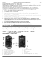
Contents: • Gasless MIG Welder • Ground Lead • MIG Torc h • Regulator
• Role of Flux core Wire 0.030 in.
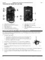
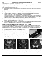
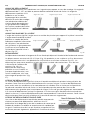
IDENTIFICATION KEY
A Wire Size Selector
B Synergic Control Knob
C Positive Outlet Socket (+)
D Negative Outlet Socket (-)
E Welding Torch Cable
F Weld Power Lead
G Input Power Cable
H Fan
I Power Switch
J Gas Inlet
K Ground Clamp cable (not shown)
Fig. 1

V1.2 PRO.POINT 105I MIG GAS/FLUX-CORED WELDER 8958696
Visit www.princessauto.com for more information 11
ASSEMBLY & INSTALLATION
Letter references in parenthesis (A) refer to the included Identification Key. Dashed numbers in
parenthesis (Fig. 1-1) refer to specific point of an illustration or image
1. Connecting the cables:
1.1 Connect the ground cable (K) into the negative outlet socket (D) when using gas or a
shielded wire.
1.2 Connect the ground cable (K) to the positive outlet socket (C)
for gasless wire.
2. Connect the power cable (F) to the opposite outlet socket.
3. Fit the gas line onto the gas inlet (J) barb. Secure with a hose clamp if
necessary.
4. Connect the gas regulator (Fig. 2) to the gas cylinder or compressor.
5. Connect the other end of the gas line to the regulator’s barbed gas outlet.
6. Install the welding wire if needed (See Wire Installation and Setup).
7. Open the valve on the gas cylinder and set the flow to 0.35 CFM (8-10 L/min).
CHECK FOR GAS LEAKAGE
Check for gas leakage after each time the welding unit is set up and at regular intervals.
The recommended procedure is as follows:
1. Connect the regulator and gas hose assembly, then tighten all connectors and clamps.
2. Slowly open the cylinder valve.
3. Set the flow rate on the regulator to approximately 0.35 CFM (8 to 10 L/min).
4. Close the cylinder valve and pay attention to the needle indicator on the regulator’s
pressure gauge. If the needle drops away towards zero there is a gas leak.
Sometimes a gas leak can be slow and to identify. Leave the gas pressure in the regulator
and line for an extended time period. Perform the test as above. Close the cylinder valve
and check after a minimum of 15 minutes.
5. After confirming there is a loss of gas, check all connectors and clamps for leakage by
brushing or spraying with soapy water. Bubbles will appear at the leakage point.
6. Tighten clamps or fittings to eliminate gas leakage. Replace the clamps and fittings if this
fails to solve the problem.
WIRE INSTALLATION AND SET UP
The correct installation of the wire spool and the wire into the wire feed unit is critical to
achieving an even and consistent wire feed. Poor set up of the wire into the wire feeder is a
major cause of fault with MIG welding machines. The guide below will assist in the correct setup
of your wire feeder.
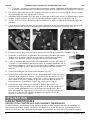
1. Open the welding unit’s top cover (Fig. 3).
2. Remove the spool retaining nut (Fig. 4). The spool
retaining nut is left-hand threaded.
3. Note the tension spring adjuster and spool locating pin
(Fig. 5).
4. Fit the wire spool onto the spool holder. Fit the locating
pin into the location hole on the spool. Reinstall the spool
retaining nut tightly (Fig. 6).
Fig. 2
Fig. 3

8958696 PRO.POINT 105I MIG GAS/FLUX-CORED WELDER V1.2
12 For technical questions call 1-800-665-8685
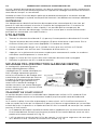
5. Choose a drive roller based on the thickness of the welding wire. Twist the retainer knob
and flip the cap up (Fig. 7). Place the roller onto the spindle with the correct wire size on
top. Flip the cap down and twist to lock in place.
5.1 Flux-Core – Install a knurled drive roller. Apply a light amount of pressure to the drive roller.
Too much pressure will crush the cored wire.
6. Loosen the tension knob and swing it up and out of the way (Fig. 8). Swing the pressure
roller arm out of the way as well.
7. Snip the wire carefully, be sure to hold the wire to prevent the spool uncoiling. Carefully
feed the wire into the inlet guide tube of the wire feed unit (Fig. 8).
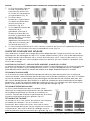
8. Feed the wire through the drive roller and into the outlet guide tube of the wire feeder.
9. Swing the pressure arm into place against the roller and lock it into place with the tension
arm. Tighten the knob to apply a medium amount of pressure (Fig. 9).
10. Remove the gas nozzle and contact tip from the torch neck (Fig. 10)
11. Press and hold the welding torch trigger to feed the wire through to the torch neck. Release
the trigger when the wire exits the torch neck.
12. Fit the correct sized contact tip and feed the wire through it, screw the contact tip into the
tip holder of the torch head. Clip the wire close to the tip unless testing the drive tension.
13. Fit the gas nozzle to the torch head (Fig. 10).
14. A simple check for the correct drive tension is
to bend the end of the wire over hold it about
4 in. from your hand and let it run into your
hand, it should coil round in your hand
without stopping and slipping at the drive
rollers, increase the tension if it slips (Fig. 11).
15. Insufficient tension on the wire spool can
allow it to spin after the wire feeding
mechanism stops, forcing loops of wire off
the spool to become tangled. Increase the
pressure on the tension spring inside the
spool holder assembly by adjusting the tension screw if this happens (Fig. 6).
Fig. 4
Fig. 5
Fig. 6
Fig. 7
Fig. 8
Fig. 9
Fig. 10
Fig. 11

V1.2 PRO.POINT 105I MIG GAS/FLUX-CORED WELDER 8958696
Visit www.princessauto.com for more information 13
OPERATION
FEATURES
THERMAL OVERLOAD PROTECTION
Constantly exceeding the duty cycle can damage the cutting unit. An internal thermal protector
will open when the duty cycle is exceeded, shutting OFF all cutting unit functions except the
cooling fan. Leave the cutting unit turned ON with the fan running. The thermal protector will
automatically reset and the cutting unit will function normally again once it has cooled.
Wait at least another 10 minutes after the thermal protector opens before resuming cutting.
Starting before this additional time may result in a shortened duty cycle.
OVER-VOLTAGE
This equipment has an automatic voltage compensation function, which enables the unit to
maintain the voltage within the given range. In case that the input voltage or amperage exceeds
the stipulated value, it is possible to damage the equipment’s components. Please ensure your
primary power supply is correct (see Specifications).
OPERATING THE WELDING UNIT
1. Switch the wire size selector (A) to match the wire diameter installed.
2. Turn the synergic control knob (B) to select the power. The higher the number, the more
power is applied to the weld.
3. Turn the gas on at the cylinder, unless you are using flux cored wire.
4. Turn the power on with the power switch (I).
5. Squeeze the welding torch trigger to start welding. The welding unit will automatically
control the wire speed.
6. Adjust the wire speed and power with the synergic control knob.
7. Release the trigger when the weld is complete.
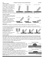
MIG (METAL INERT GAS) WELDING
MIG (metal inert gas) welding, also
known as GMAW (gas metal arc welding)
or MAG (metal active gas welding), is a
semi-automatic or automatic welding
process in which a continuous and
consumable wire welding wire and a
shielding gas are fed through a welding
torch. A constant voltage, direct current
power source is most commonly used
with MIG welding.
SHORT-CIRCUIT TRANSFER
Short-circuit transfer is the most common used method. The wire welding wire is fed
continuously down the welding torch until it exits from the contact tip. The wire touches the
workpiece and causes a short-circuit. The wire heats up and begins to form a molten bead, the
bead separates from the end of the wire and forms a droplet that is transferred into the weld
pool. This process is repeated about 100 times per second, making the arc appear constant to
the human eye.
1. The wire approaches the workpiece and touches the work creating a short-circuit between
the wire and the base metal, because there is no space between the wire and the base
metal there is no arc and current flows through the wire (Fig. 13)
Fig. 12

8958696 PRO.POINT 105I MIG GAS/FLUX-CORED WELDER V1.2
14 For technical questions call 1-800-665-8685
2. The wire cannot support
all the current flow;
resistance builds up and
the wire becomes hot and
weak and begins to melt
(Fig. 14)
3. The current flow creates a
magnetic field that begins
to pinch the melting wire
forming it into droplet
(Fig. 15).
4. The pinch causes the
forming droplet to
separate and fall to-wards
the now creating weld
pool (Fig. 16).
5. An arc is created at the
separation of the droplet
and the heat and force of
the arc flattens out the
droplet into the weld pool. The heat of the arc melts the end of the wire slightly as it feeds
towards the base metal (Fig. 17).
6. The wire feed speed overcomes the heat of the arc and the wire again approaches the work
to short-circuit and repeat the cycle (Fig. 18).
BASIC MIG WELDING GUIDE
Good weld quality and weld profile depends on the gun angle, direction of travel, welding wire
extension (stick out), travel speed, thickness of base metal, wire feed speed (amperage) and arc
voltage. To follow are some basic guides to assist with your setup.
GUN POSITION - TRAVEL DIRECTION, WORK ANGLE
Gun position or technique usually refers to how the wire is directed at the base metal, the angle
and travel direction chosen. Travel speed and work angle will determine the characteristic of the
weld bead profile and degree of weld penetration.
PUSH TECHNIQUE
The wire is located at the leading edge of the weld pool and pushed towards the un-melted
work surface. This technique offers a better view of the
weld joint and direction of the wire into the weld joint.
Push technique directs the heat away from the weld
puddle allowing faster travel speeds providing a flatter
weld profile with light penetration - useful for welding
thin materials. The welds are wider and flatter allowing for
minimal clean up / grinding time (Fig. 19).
PERPENDICULAR TECHNIQUE
The wire is fed directly into the weld, this technique is
used primarily for automated situations or when
conditions make it necessary. The weld profile is generally
higher and a deeper penetration is achieved (Fig. 20).
DRAG TECHNIQUE
The gun and wire are dragged away from the weld bead. The arc and heat are concentrated on the
weld pool, the base metal receives more heat, deeper melting, more penetration and the weld
profile is higher with more build up (Fig. 21)
Fig. 13
Fig. 14
Fig. 15
Fig. 16
Fig. 17
Fig. 18
Fig. 21
Fig. 19
Fig. 20

V1.2 PRO.POINT 105I MIG GAS/FLUX-CORED WELDER 8958696
Visit www.princessauto.com for more information 15
TRAVEL ANGLE
Travel angle is the right to left
angle relative to the direction
of welding. A travel angle of 5°
to 15° is ideal and produces a
good level of control over the
weld pool. A travel angle
greater that 20° will give an
unstable arc condition with
poor weld metal transfer, less
penetration, high levels of spatter, poor gas shield and poor-quality finished weld (Fig. 22)
ANGLE TO WORK
The work angle is the forward or
back angle of the gun relative to
the workpiece.
The correct work angle provides
good bead shape, prevents
undercut, uneven penetration,
poor gas shield and poor-quality
finished weld (Fig. 23).
STICK OUT
Stick out is the length of the unbelted wire protruding from the end of the contact tip.
A constant even stick out of 1/8 to 1/4 in. (Fig. 24) will produce a stable arc and an even current
flow providing good penetration and even fusion (Fig. 25). A stick out that is too short will cause an
unstable weld pool, produce
spatter and overheat the
contact tip (Fig. 26). A stick
out too long will cause an
unstable arc, lack of
penetration, lack of fusion and
increase spatter (Fig. 27).
TRAVEL SPEED
Travel speed is the rate that the gun is moved along the weld joint and is usually measured in mm
per minute. Travel speeds can vary depending on conditions and the welder’s skill and is limited to
the welder’s ability to control the weld pool. Push technique allows faster travel speeds than Drag
technique. Gas flow must also correspond with the travel speed, increasing with faster travel speed
and decreasing with slower speed. Travel speed needs to match the amperage and will decrease as
the material thickness and amperage increase.
TOO FAST TRAVEL SPEED
A too fast travel speed produces too little heat per inch of
travel resulting in less penetration and reduced weld fusion, the
weld bead solidifies very quickly trapping gases inside the weld
metal causing porosity. Undercutting of the base metal can also
occur and an unfilled groove in the base metal is created when
the travel speed is too fast to allow molten metal to flow into
the weld crater created by the arc heat (Fig. 28).
TOO SLOW TRAVEL SPEED
A too slow travel speed produces a large weld with lack of
penetration and fusion. The energy from the arc dwells on top of
the weld pool rather than penetrating the base metal. This
produces a wider weld bead with more deposited weld metal
per mm than is required resulting in a weld deposit of poor
quality (Fig. 29).
Fig. 22
Angle 5° to 15°
Not Enough Angle
Angle more than 20°
Fig. 23
Correct Angle
Not Enough Angle
Too Much Angle
Fig. 24
Fig. 25
Fig. 26
Fig. 27
Fig. 28
Fig. 29

8958696 PRO.POINT 105I MIG GAS/FLUX-CORED WELDER V1.2
16 For technical questions call 1-800-665-8685
CORRECT TRAVEL SPEED
The correct travel speed keeps the arc at the leading edge of
the weld pool allowing the base metal to melt sufficiently to
create good penetration, fusion and wetting out of the weld
pool, producing a weld deposit of good quality (Fig. 30).
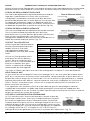
WIRE TYPES AND SIZES
Use the correct wire type for the base
metal being welded. Use stainless steel
wire for stainless steel and steel wires for
steel.
Use a smaller diameter wire for thin base
metals. For thicker materials use a larger
wire diameter and larger machine, check
the recommended welding capability of
your machine.
As a guide refer to the Welding Wire
Thickness Chart in Table 3.
GAS SELECTION
The purpose of the gas in the MIG process is to protect/shield the wire, the arc and the
molten weld metal from the atmosphere. Most metals when heated to a molten state will react with
the air. Without the protection of the shielding gas, the weld produced would contain defects like
porosity, lack of fusion and slag inclusions. Some of the gas becomes ionized (electrically charged)
and helps the current flow smoothly.
The correct gas flow is also very important in protecting the welding zone from the atmosphere. Too
low of a flow will give inadequate coverage and result in weld defects and unstable arc conditions.
Too high of a flow can cause air to be drawn into the gas column and contaminate the weld zone.
USE THE CORRECT SHIELDING GAS
Co2 is good for steel and offers good penetration characteristics,
the weld profile is narrower and slightly raised than the weld profile
obtained from an Argon/Co2 mixed gas. Argon/Co2 mix gas offers
better weld ability for thin metals and has a wider range of setting
tolerance on the machine. Argon 75%/Co2 25% is a good all round
mix suitable for most applications (Fig. 31)
CARE & MAINTENANCE
1. Maintain the tool with care. A tool in good condition is efficient, easier to control and will
have fewer problems.
2. Inspect the tool fittings, alignment, hoses and power supply cord periodically. Have damaged
or worn components repaired or replaced by an authorized technician. Only use identical
replacement parts when servicing.
3. Exposure to extremely dusty, damp, or corrosive air is damaging to the welding unit. In
order to prevent possible failure or fault of this welding equipment, clean the dust at regular
intervals with clean and dry compressed air.
4. Follow instructions for lubricating and changing accessories.
5. Only use accessories intended for use with this tool.
6. Keep the tool handles clean, dry and free from oil/grease at all times.
7. Maintain the tool’s labels and name plates. These carry important information. If unreadable
or missing, contact Princess Auto Ltd. for replacements.
WARNING! Only qualified service personnel should repair the tool. An improperly repaired
tool may present a hazard to the user and/or others.
WELDING WIRE THICKNESS CHART
RECOMMENDED WIRE DIAMETERS
MATERIAL
THICKNESS
MIG SOLID WIRE
GASLESS FLUX-
CORED WIRE
0.023 in.
0.030 in.
0.035 in.
0.30 in.
0.035 in.
24 Gauge (.60 mm)
22 Gauge (.75 mm)
20 Gauge (.90 mm)
18 Gauge (1.0 mm)
16 Gauge (1.2 mm)
14 Gauge (1.9 mm)
0.118 in. / 3 mm
0.196 in. / 5 mm
Table 3
Fig. 31
Fig. 30

V1.2 PRO.POINT 105I MIG GAS/FLUX-CORED WELDER 8958696
Visit www.princessauto.com for more information 17
DISPOSAL
Recycle a tool damaged beyond repair at the appropriate facility.
Contact your local municipality for a list of disposal facilities or by-laws for electronic devices,
batteries, oil or other toxic liquids.
TROUBLESHOOTING
Visit a Princess Auto Ltd. location for a solution if the tool does not function properly or parts
are missing. If unable to do so, have a qualified technician service the tool.
MIG WELDING
PROBLEM(S)
POSSIBLE CAUSE(S)
SUGGESTED SOLUTION(S)
Excessive Spatter 1. Voltage too high.
2. Wrong polarity set.
3. Stick out too long.
4. Contaminated base
metal.
5. Contaminated MIG wire.
6. Inadequate gas flow or
too much gas flow.
1. Select a lower voltage setting.
2. Select the correct polarity for the wire being used -
see machine setup guide.
3. Bring the torch closer to the work.
4. Remove materials like paint, grease, oil and dirt,
including mill scale from base metal.
5. Use clean dry rust free wire. Do not lubricate the
wire with oil, grease etc.
6. Check the gas is connected, check hoses, gas valve
and torch are not restricted. Set the gas flow rate to
0.35 CFM (8-10 L/min). Check hoses and fittings for
holes, leaks etc. Protect the welding zone from wind
and drafts.
Porosity - small
cavities or holes
resulting from gas
pockets in weld metal.
1. Wrong gas.
2. Inadequate gas flow or
too much gas flow.
3. Moisture on the base
metal.
4. Contaminated base
metal.
5. Contaminated MIG wire.
6. Gas nozzle clogged with
spatter, worn or out of
shape
7. Missing or damaged gas
diffuser.
1. Check that the correct gas is being used.
2. Check the gas is connected, check hoses, gas valve
and torch are not restricted. Set the gas flow rate to
.35 CFM (8-10 L/min). Check hoses and fittings for
holes, leaks etc. Protect the welding zone from wind
and drafts.
3. Remove all moisture from base metal before
welding.
4. Remove materials like paint, grease, oil and dirt,
including mill scale from base metal.
5. Use clean dry rust free wire. Do not lubricate the
wire with oil, grease etc.
6. Clean or replace the gas nozzle.
7. Replace the gas diffuser.
Wire stubbing during
welding
1. Holding the torch too far
away.
2. Welding voltage set too
low.
1. Bring the torch closer to the work and maintain
stick out of 3/16 to 3/8 in.
2. Increase the voltage.
Lack of Fusion − failure
of weld metal to fuse
completely with base
metal or a proceeding
weld bead
1. Contaminated base
metal.
2. Not enough heat input.
3. Improper welding
technique.
1. Remove materials like paint, grease, oil and dirt,
including mill scale from base metal.
2. Select a higher voltage range and /or adjust the wire
speed to suit.
3. Keep the arc at the leading edge of the weld pool.
Gun angle to work should be between 5 and 15°.
Direct the arc at the weld joint Adjust work angle or
widen groove to access bottom during welding.
Momentarily hold arc on side walls if using weaving
technique.
Excessive Penetration
− weld metal melting
through base metal
Too much heat. Select a lower voltage range .

8958696 PRO.POINT 105I MIG GAS/FLUX-CORED WELDER V1.2
18 For technical questions call 1-800-665-8685
MIG WIRE FEED
APPENDIX A
PROBLEM(S)
POSSIBLE CAUSE(S)
SUGGESTED SOLUTION(S)
Lack of Penetration −
shallow fusion
between weld metal
and base metal
1. Poor in incorrect joint
preparation.
2. Not enough heat input.
3. Contaminated base
metal.
1. Material too thick. Joint preparation and design
needs to allow access to bottom of groove while
maintaining proper welding wire extension and arc
characteristics. Keep the arc at the leading edge of
the weld pool and maintain the gun angle at 5 and
15° keeping the stick out between 3/16 to 3/8 in.
2. Select a higher voltage range and /or adjust the wire
speed to suit Reduce travel speed.
3. Remove materials like paint, grease, oil and dirt,
including mill scale from base metal.
PROBLEM(S)
POSSIBLE CAUSE(S)
SUGGESTED SOLUTION(S)
Inconsistent /
interrupted
wire feed
1. Wrong polarity selected.
2. Incorrect wire speed setting.
3. Voltage setting incorrect.
4. MIG torch lead kinked or too
sharp angle being held.
5. Contact tip worn, wrong size,
wrong type.
6. Liner worn or clogged (the
most common causes of bad
feeding).
7. Blocked or worn inlet guide
tube.
8. Wire misaligned in drive roller
groove.
9. Incorrect drive roller size.
10. Wrong type of drive roller
selected.
11. Worn drive rollers.
12. Drive roller pressure too high.
13. Too much tension on wire spool
hub.
14. Wire crossed over on the spool
or tangled.
15. Contaminated MIG wire.
1. Select the correct polarity for the wire being
used - see machine setup guide.
2. Adjust the wire feed speed.
3. Adjust the voltage setting.
4. Remove the kink, reduce the angle or bend.
5. Replace the tip with correct size and type.
6. Try to clear the liner by blowing out with
compressed air as a temporary cure, it is
recommended to replace the liner.
7. Clear or replace the inlet guide tube.
8. Locate the wire into the groove of the drive roller.
9. Fit the correct size drive roller eg; 0.030 in. wire
requires 0.030 in. drive roller.
10. Fit the correct type roller (e.g. knurled rollers
needed for flux cored wires).
11. Replace the drive rollers.
12. Can flatten the wire welding wire causing it to lodge
in the contact tip - reduce the drive roller pressure.
13. Reduce the spool hub brake tension.
14. Remove the spool untangle the wire or replace the
wire.
15. Use clean dry rust free wire. Do not lubricate the wire
with oil, grease etc.

V1,2 8958696
Vous devez lire et comprendre toutes les instructions avant d'utiliser l'appareil. Conservez ce manuel afin
de pouvoir le consulter plus tard.
SOUDEUSE MIG À ESSENCE/FIL
FOURRÉ PRO.POINT 105I
MANUEL D'UTILISATEUR

8958696 SOUDEUSE MIG À ESSENCE/FIL FOURRÉ PRO.POINT 105I V1,2
2 En cas de questions techniques, appelez le 1-800-665-8685
SPÉCIFICATIONS
Tension d'entrée
115 V c.a.
Plage de courant de sortie 40 à 105 A
Débit en ampères max. 26,5 A
Puissance de sortie de soudage MIG à un
cycle de service de 20 %
105 A
Sortie CA/CC
CC
Tension à vide 46 V
Capacité de soudage
3/16 po acier doux et Acier inoxydable
Vitesse du dévidoir de fil Automatique
Diamètre du fil de soudage (MIG-ARC-TIG)
0,023 / 0,030 / 0,035 po
Type d’électrode FCAW : AWS E71T-GS et GMAW : AWS ER70S-6
Gaz de soudage requis
Argon, mélange argon et CO2 mix, ou CO2 (adaptateur nécessaire)
Catégorie d'isolant B
Facteur puissance
0,74
Dimensions 14 à 5,2 à 9,85 po
Compatible avec une génératrice Oui
Poids 13 lb
INTRODUCTION
La soudeuse MIG à essence/fil fourré Pro.Point 105i intègre la version la plus récente de la
technologie de transistor bipolaire à porte isolée procurant une efficacité maximale et un cycle
de service prolongé. La soudeuse possède à la fois une option avec gaz et une option sans gaz.
La vitesse du dévidoir de fil est étalonnée automatiquement en fonction du calibre du fil et des
réglages du bouton de commande synergique.
SÉCURITÉ
AVERTISSEMENT ! Veuillez lire et comprendre toutes les instructions avant d'utiliser cet outil.
L'utilisateur doit respecter les précautions de base lorsqu'il utilise cet outil afin de réduire le
risque de blessure ou de dommage à l'équipement.
Conservez ce manuel qui contient les avertissements de sécurité, les précautions, les
instructions de fonctionnement ou d'inspection et d'entretien.
DÉFINITIONS DE DANGER
Veuillez-vous familiariser avec les avis de danger qui sont présentés dans ce manuel. Un avis est
une alerte indiquant qu'il existe un risque de dommage à la propriété, de blessure ou de décès
si on ne respecte pas certaines instructions.
DANGER ! Cet avis indique un risque immédiat et particulier qui entraînera des
blessures corporelles graves ou même la mort si on omet de prendre
les précautions nécessaires.
SOUDEUSE MIG À ESSENCE/FIL
FOURRÉ PRO.POINT 105I
La page est en cours de chargement...
La page est en cours de chargement...
La page est en cours de chargement...
La page est en cours de chargement...
La page est en cours de chargement...
La page est en cours de chargement...
La page est en cours de chargement...
La page est en cours de chargement...
La page est en cours de chargement...
La page est en cours de chargement...
La page est en cours de chargement...
La page est en cours de chargement...
La page est en cours de chargement...
La page est en cours de chargement...
La page est en cours de chargement...
La page est en cours de chargement...
La page est en cours de chargement...
La page est en cours de chargement...
La page est en cours de chargement...
La page est en cours de chargement...
-
 1
1
-
 2
2
-
 3
3
-
 4
4
-
 5
5
-
 6
6
-
 7
7
-
 8
8
-
 9
9
-
 10
10
-
 11
11
-
 12
12
-
 13
13
-
 14
14
-
 15
15
-
 16
16
-
 17
17
-
 18
18
-
 19
19
-
 20
20
-
 21
21
-
 22
22
-
 23
23
-
 24
24
-
 25
25
-
 26
26
-
 27
27
-
 28
28
-
 29
29
-
 30
30
-
 31
31
-
 32
32
-
 33
33
-
 34
34
-
 35
35
-
 36
36
-
 37
37
-
 38
38
-
 39
39
-
 40
40


PROPOINT 8958696 Le manuel du propriétaire
- Catégorie
- Système de soudage
- Taper
- Le manuel du propriétaire
dans d''autres langues
- English: PROPOINT 8958696 Owner's manual
Documents connexes
Autres documents
-
PRO POINT 8958696 Manuel utilisateur
-
Powerfist 9038787 Le manuel du propriétaire
-
-
Power Fist 8785115 Manuel utilisateur
-
-
-
Lincoln Electric SP100 Mode d'emploi
-
 Tweco FABRICATOR 252i Mode d'emploi
-
 Tweco FABRICATOR® 141i 3-IN-1 Multi Process Welding Systems Manuel utilisateur
-
ESAB Firepower MST 140i 3-IN-1 Multi Process Welding System Manuel utilisateur

