Powerfist 8976052 Le manuel du propriétaire
- Catégorie
- Système de soudage
- Taper
- Le manuel du propriétaire

8976052 V4.0
Please read and understand all instructions before use. Retain this manual for future
reference.
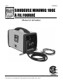
User Manual
MINIMIG 100E
Flux-Cored Welder

8976052 MINIMIG 100E Flux-Cored Welder V4.0
2 For technical questions call 1-800-665-8685
SPECIFICATIONS
Input Voltage 120V AC
Duty Cycle 20% at 80A
Metal Type Steel
Output Current 60 to 80A (peak 125A)
Max. Amperage Draw 125A
Current Range 60 to 80A (peak 125A)
Mild Steel Weld Thickness Range 18 gauge to 3/16 in.
AC/DC Output AC
Generator Compatible Yes
Electrode Type Flux core wire
Electrode Size 0.030 / 0.035 in.
Dimensions 17.56 x 9.65 x 14.37 in.
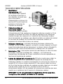
INTRODUCTION
Your new MIG (Metal Inert Gas) wire feed welder is designed for maintenance
and sheet metal fabrication. The welding unit consists of a single-phase power
transformer, stabilizer, rectifier and a wire feeder. The welding unit features a
stepless wire feed speed setting and includes thermal protection.
SAFETY
WARNING! Read and understand all instructions before using this tool. The
operator must follow basic precautions to reduce the risk of personal injury
and/or damage to the equipment.
Keep this manual for safety warnings, precautions, operating or inspection and
maintenance instructions.
HAZARD DEFINITIONS
Please familiarize yourself with the hazard notices found in this manual. A
notice is an alert that there is a possibility of property damage, injury or death
if certain instructions are not followed.
DANGER! This notice indicates an immediate and specific hazard that will
result in severe personal injury or death if the proper
precautions are not taken.
WARNING! This notice indicates a specific hazard or unsafe practice that
could result in severe personal injury or death if the proper
precautions are not taken.

V4.0 MINIMIG 100E Flux-Cored Welder 8976052
Visit www.princessauto.com for more information 3
CAUTION! This notice indicates a potentially hazardous situation that may
result in minor or moderate injury if proper practices are not
taken.
NOTICE! This notice indicates that a specific hazard or unsafe practice will
result in equipment or property damage, but not personal injury.
WORK AREA
1. Operate in a safe work environment. Keep your work area clean, well lit
and free of distractions.
2. Keep anyone not wearing the appropriate safety equipment away from the
work area.
3. Store tools properly in a safe and dry location. Keep tools out of the reach
of children.
4. Do not install or use in the presence of flammable gases, dust or liquids.
5. Check that the work area is free from fires, sparks or hot debris before
leaving.
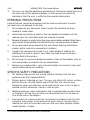
PERSONAL SAFETY
WARNING! Wear personal protective equipment approved by the Canadian
Standards Association (CSA) or American National Standards Institute
(ANSI).
PERSONAL PROTECTIVE EQUIPMENT
1. Non-skid footwear is recommended to maintain footing and balance in the
work environment.
2. Steel toe footwear or steel toe caps to prevent injury from falling objects.
HEAD PROTECTION
DANGER! Never look directly at the welding arc without the proper
protection. The light can cause flash burn damage and impair vision.
Although treatment is possible, multiple occurrences can result in
permanent eye damage.
1. Protect your eyes from welding light by wearing a welder's helmet fitted
with a filter shade suitable for the type of welding you are doing. The
welding process produces intense white light, infrared and ultraviolet
light, these arc rays can burn both eyes and skin.
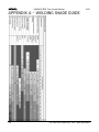
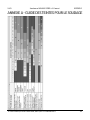
a. Consult the Welding Shade Guide in Appendix A for the minimum
shade to protect the eyes based on the amperage and type of
welding.

8976052 MINIMIG 100E Flux-Cored Welder V4.0
4 For technical questions call 1-800-665-8685
2. An opaque helmet will protect against the ultraviolet or infrared light. A
helmet will also protect against ejected hot material and slag.
3. Wear a fire-resistant head covering like a skull cap or balaclava hood to
protect your head when the faceplate is down or when using a welding
hand shield.
4. Wear safety goggles beneath the welding helmet or behind the hand
shield. The cooling weld bead may fragment or eject slag that can damage
the eyes, when the helmet or hand shield is not in place.
5. Wear ear plugs when welding overhead to prevent spatter or slag from
falling into ear.
PROTECTIVE CLOTHING
1. Wear protective clothing made from durable, flame resistant materials,
leather welding gloves and full foot protection.
2. Wear a leather apron or jacket, leather welding gloves and fire-resistant
footwear when welding. Wear thick clothes that do not expose the skin.
Ultraviolet or infrared light can burn skin with sufficient exposure.
3. Choose clothing fabrics that resist sparks, heat and flames. Artificial
fabrics may burn and melt, resulting in a more severe injury.
4. Do not wear clothing that can hold hot debris or sparks such as pant
cuffs, shirt pockets or boots. Choose clothing that has flaps over pockets
or wear clothing to cover the openings such as pant legs over the boots or
an apron over the shirt.
5. Remove all jewelry before proceeding to weld
6. Wear protective clothing made from durable, flame resistant materials,
leather welding gloves and full foot protection.
7. Use protective screens or barriers to protect others from flash and glare;
warn others in the area to look away from the arc.
RESPIRATORS
1. Respiratory protection is needed when ventilation is not sufficient to
remove welding fumes or when there is risk of oxygen deficiency.
a. Wear a NIOSH approved respirator when working on materials that
produce dust or particulate matter.
2. Work in a confined space only if it is well ventilated or while wearing an
air-supplied respirator. Welding fumes and gases can displace air and
lower the oxygen level causing injury or death. Be sure the breathing air is
safe.

V4.0 MINIMIG 100E Flux-Cored Welder 8976052
Visit www.princessauto.com for more information 5
3. The user can take the additional precaution of informing another person in
the work area of the potential danger, so that person can watch for
indications that the user is suffering from oxygen deprivation.
PERSONAL PRECAUTIONS
Control the tool, personal movement and the work environment to avoid
personal injury or damage to the tool.
1. Do not operate any tool when tired or under the influence of drugs,
alcohol or medications.
2. Avoid wearing clothes or jewelry that can become entangled with the
moving parts of a tool. Keep long hair covered or bound.
3. Remove all jewelry or metal items from your person before welding. Metal items
may connect to the welding unit’s electrical circuit, causing an injury or death.
4. Do not overreach when operating the tool. Proper footing and balance
enables better control in unexpected situations.
5. Support the workpiece or clamp it to a stable platform. Holding the
workpiece by hand or against your body may lead to personal injury.
General Safety Precautions
6. Do not wear any personal grooming products that are flammable, such as
hair preparations or cologne with an alcohol base.
7. Remove any combustibles, such as butane lighters or matches, from your
person before doing any welding.
SPECIFIC SAFETY PRECAUTIONS
1. Arc Welding requires the use a hand shield or helmets with full face
protection per CSA standard Z94.3.1.
2. Protect against reflected arc rays. The rays can reflect off a shiny surfaces
behind the user, into the helmet and off the filter lens into the eyes.
Remove or cover any reflective surface behind the user such as a glossy
painted surface, aluminum, stainless steel or glass.
3. Welding produces sparks and molten slag. A cooling bead can eject chips
or fragments of slag. Any of these can cause direct harm to the eyes or
skin of the user or bystanders.
4. Erect protective screens or barriers to protect bystanders from the flash
and glare; warn others In the area not to watch the arc. Do not strike a
welding arc until all bystanders and you (the user) have welding shields
and/or helmets in place.

8976052 MINIMIG 100E Flux-Cored Welder V4.0
6 For technical questions call 1-800-665-8685
5. Immediately replace a cracked or broken helmet or a scratched or
damaged lens filter to avoid damage to the eyes or face from arc flash or
ejected molten material.
6. Do not allow the uninsulated portion of the wire feed torch to touch the
ground clamp or grounded work. An arc flash will result from contact and
can injury the unprepared user and bystanders.
7. Do not handle hot metal or electrode stubs with bare hands. Handling may
result in a burn injury.
8. Do not use the welding unit if personal movement is confined or if there is
a danger of falling.
9. Keep all panels and covers securely in place when operating the welding unit.
10. Insulate the work clamp when not connected to a workpiece to prevent
contact with any metal object.
11. Do not operate the welder if the output cable, MIG gun, wire or wire feed
system is wet. Do not immerse them in water. These components and the
welder must be completely dry before attempting to use them.
12. Do not point the MIG gun at any body part of yourself or at anyone else.
13. Do not use a welder to thaw frozen pipes.
FIRE AND EXPLOSION PRECAUTIONS
Arc welding can produce sparks, hot slag or spatter, molten metal drops and
hot metal parts that can start fires.
1. Clear the floor and walls of an area of all combustible and/or flammable
materials. Hot debris ejected during welding can land at a considerable
distance way. Solid floors of concrete or masonry is the preferred
working surface.
a. Cover any combustible material with fire resistant covers or shields,
if it cannot be removed.
2. Check that there are no openings or cracks that hot debris can enter.
3. Check both sides of a panel or wall for combustible material. Remove the
combustible material before welding.
4. Have a fire extinguisher available for immediate use. A dry chemical fire
extinguisher with
Types A, B and C is suggested.
a. Welding a combustible metal like zinc, magnesium or titanium
requires a Type D fire extinguisher.

V4.0 MINIMIG 100E Flux-Cored Welder 8976052
Visit www.princessauto.com for more information 7
b. Do not use liquid based fire extinguishing methods near the electric
arc welding unit, as it may cause a shock hazard.
5. Do not perform any welding work on containers that held flammable or
toxic substance until they are cleaned by a person trained in removing
toxic and flammable substances and vapours.
6. Open a container before performing any welding work on it. The heat
generated by the welding process will cause the air and gases to expand.
The internal pressure may cause a sealed or closed container to rupture,
possibly causing an injury or death.
FUMES AND GASES
Welding may produce hazardous fumes and gas during the welding process. A well
ventilated work area can normally remove the fumes and gases, but sometimes
the welding produces fumes and gases that are hazardous to your health.
Stop welding if your eyes, nose or throat become irritated. This indicates the
ventilation is not adequate to remove the fumes. Do not resume welding until
the ventilation is improved and the discomfort ceases.
1. Only work in a confined space if the area is well ventilated or while
wearing an air-supplied respirator. Always have a trained watchperson
nearby.
2. Avoid positions that allow welding fumes to reach your face.
3. Ventilate the work area to remove welding fumes and gases. The fumes
and gases should be drawn away from the user. Welding fumes and gases
can displace air and lower the oxygen level causing injury or death. Be
sure the breathing air is safe.
a. If ventilation in the work area is poor, use an approved air-supplied
respirator. All the people in the work area must also have air-supplied
respirators.
4. Avoid welding in a work area that has vapours from cleaning, degreasing
or any spraying operations. The heat and light from welding can react
with the vapour and form irritating or potentially toxic gases. Wait for the
vapours to disperse.
5. Consult the manufacturer's Material Safety Data Sheets (MSDS) for
instructions and precautions about metals, consumables, coatings,
cleaners and degreasers.
a. Do not weld on coated metals such as galvanized, lead or cadmium
plated steel, unless the coating is removed from the weld area. The

8976052 MINIMIG 100E Flux-Cored Welder V4.0
8 For technical questions call 1-800-665-8685
coatings and any metals containing these elements can give off toxic
fumes during the welding process.
b. Do not weld, cut or heat lead, zinc, cadmium, mercury, beryllium or
similar metals without seeking professional advice and inspection of
the welding area’s ventilation. These metals produce extreme toxic
fumes, which can cause discomfort, illness and death.
c. Do not weld or cut near chlorinated solvents or in areas that
chlorinates solvents can enter. The heat or ultraviolet light of the arc
can separate chlorinated hydrocarbons into a toxic gas (phosgene)
that can poison or suffocate the user or bystanders.
ELECTROMAGNETIC FIELDS
Electromagnetic Fields (EMF) can interfere with electronic devices such as
pacemakers. Anyone with a pacemaker should consult with their doctor before
working with or near an arc welding unit. The following steps can minimize the
effects of electromagnetic fields.
1. Twist or tape cables together and prevent coils.
2. Do not drape cables on your body.
3. Keep the welding power source and cables as far away from the user as
practical. A minimum of 24 in. is recommended.
4. Connect the workpiece clamp as close to the weld as possible, but lay the
electrode and workpiece cables away from the user.
5. Avoid long and regular bursts of energy while welding. Apply the
electrode in short strokes and intermittently. This will prevent the
pacemaker from interpreting the signal as a rapid heartbeat.
6. Do not allow the electrode to touch the metal while welding.
7. Wrap MIG gun and ground cable together whenever possible.
8. Keep MIG gun and ground cables on the same side of your body.
ELECTRICAL SAFETY
WARNING! To reduce risk of electric shock, be certain that the plug is
connected to a properly grounded outlet.
1. Do not come into physical contact with the welding current circuit. The
welding current circuit includes:
a. the workpiece or any conductive material in contact with it;
b. the ground clamp;

V4.0 MINIMIG 100E Flux-Cored Welder 8976052
Visit www.princessauto.com for more information 9
c. the electrode or welding wire;
d. any metal parts on the electrode holder or wire feed torch.
2. Insulate yourself from the electrical current and ground using dry
insulating mats or covers big enough to prevent physical contact with the
workpiece or ground.
3. Disconnect the tool from the power source before cleaning, servicing,
changing parts/accessories or when not in use.
4. Protect yourself against electric shocks when working on electric
equipment. Avoid body contact with grounded surfaces. There is an
increased chance of electrical shock if your body is grounded.
5. Do not expose the tool to rain or wet conditions. Water entering a power
tool will increase the risk of electric shock.
6. Do not disconnect the power cord in place of using the ON/OFF switch on
the tool. This will prevent an accidental startup when the power cord is
plugged into the power supply.
7. Do not alter any parts of the tool or accessories. All parts and accessories are
designed with built-in safety features that may be compromised if altered.
8. Make certain the power source conforms to requirements of your
equipment (see Specifications).
9. When wiring an electrically driven device, follow all electrical and safety
codes, as well as the most recent Canadian Electrical Code (CE) and
Canadian Centre for Occupational Health and Safety (CCOHS).
WARNING! All wiring should be performed by a qualified electrician.
ELECTRIC POWER TOOL PRECAUTIONS
This equipment requires a dedicated 120 volt, 20 amp single-phase alternating
current circuit equipped with a similarly rated circuit breaker or slow blow
fuse. Do not run other appliances, lights, tools or equipment on the circuit
while operating this welding unit.
1. Do not use a power tool with a broken or inoperative trigger/power switch
or safety guard.
2. Make sure the power switch is in the OFF position before connecting the
tool to the power supply.
3. Do not drape or carry coiled welding cables on your body when the cables
are plugged into the welding unit.
4. Do not start the tool when the welding wire is touching the workpiece.

8976052 MINIMIG 100E Flux-Cored Welder V4.0
10 For technical questions call 1-800-665-8685
5. Always use both hands when operating the tool, unless the tool is
designed for single hand use.
6. Hold the tool by the insulated gripping surfaces when performing an
operation where it may contact hidden wiring or its own cord. Contact
with a ‘live’ wire will electrify exposed metal parts and shock the operator.
7. Do not allow the tool's motor to overload and/or overheat by taking work
breaks.
8. When the tool is in operation, keep hands away from the welding wire and
the area it is being applied to.
9. Do not connect the welding unit ground clamp to an electrical conduit. Do
not weld on an electrical conduit.
10. Do not use the tool on any material containing asbestos.
11. Do not touch the welding wire or welded surface immediately after use.
The surface will be hot and may cause an injury.
12. Do not allow persons who are not familiar with the tool or have not read
these instructions to use the tool.
POWER CORD
1. Insert the power cord plug directly to the power supply whenever possible.
Extension cords are not recommended for use with this welding unit.
2. Do not operate this tool if the power cord is frayed, damaged or poorly
spliced, as an electric shock may occur, resulting in personal injury or
property damage.
a. Inspect the tool's power cord for cracks, fraying or other faults in the
insulation or plug before each use.
b. Discontinue use if a power cord feels more than comfortably warm
while operating the tool.
c. Have the power cord replaced by a qualified service technician.
3. Keep all connections dry and off the ground to reduce the risk of electric
shock. Do not touch plug with wet hands.
4. Prevent damage to the power cord by observing the following:
a. Never use the cord to carry the tool.
b. Do not pull on the cord to disconnect the plug from an outlet.
c. Keep the power cord clear of the tool and the tool's work path while
in operation. The cord should always stay behind the tool.

V4.0 MINIMIG 100E Flux-Cored Welder 8976052
Visit www.princessauto.com for more information 11
d. Keep cord away from heat, oil, sharp edges or moving parts.
5. Do not allow people, mobile equipment or vehicles to pass over
unprotected power cords.
a. Position power cords away from traffic areas.
b. Place cords in reinforced conduits.
c. Place planks on either side of the power cord to create a protective
trench.
6 Do not wrap cord around tool, as sharp edges may cut insulation or cause
cracks if wound too tight. Gently coil cord and either hang on a hook or
fasten with a device to keep cord together during storage.
USE AND CARE OF THE TOOL
1. Use the correct tool for the job. This tool was designed for a specific
function. Do not modify or alter this tool or use it for an unintended
purpose.
2. Do not carry the tool with fingers near or on the trigger/switch.
3. Avoid unintentional starts. Be sure that the ignition switch/trigger is in the
neutral or OFF position when not in use or before connecting it to any
power source.
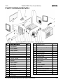
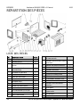
PARTS IDENTIFICATION
WARNING! Do not operate the tool if any part is missing. Replace the
missing part before operating. Failure to do so could result in a malfunction
and personal injury.
Remove the parts and accessories from the packaging and inspect for damage.
Make sure that all items in the parts list are included.
Contents:
• Welding Unit
• MIG Gun with Cable
• Ground Cable with Clamp
• Nozzle
• 0.035 contact tip
• Wire, Flux-cored .030
• Brush/Chipping
Hammer

8976052 MINIMIG 100E Flux-Cored Welder V4.0
12 For technical questions call 1-800-665-8685
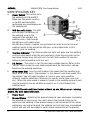
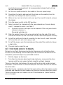
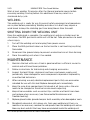
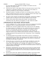
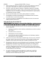
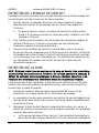
IDENTIFICATION KEY
A. Power Switch -This switch turns
the welding unit ON and OFF.
Make sure the power switch is
in the OFF position before
performing any maintenance on
the welding unit.
B. MIG Gun with Cable - The MIG
gun controls the delivery of
the welding wire to the
material to be welded. the
welding wire is fed through
the MIG gun with cable when
the MIG gun trigger is pulled. you will need to install a contact tip and
welding nozzle to the end of the MIG gun, as described later in this
manual, prior to welding.
C. Thermal Indicator - The thermal indicator light will glow and the welding
until will shut down when the unit overheats. Once the unit cools to the
operating temperature the light will shut off. Wait another 15 minutes
before resuming welding with this unit.
D. 1/2 Switch – The switch is for the two main voltage choices. Refer to the
"set up" chart inside the wire feed compartment for the correct voltage
based on the welding operation.
E. Wire Speed Dial - Use this dial to adjust the speed that the welding unit
feeds wire to the torch. The number 1 is the slowest wire feed speed, 10 is
the highest. You will need to adjust or ‘tune in’ your wire speed for
different welding conditions (thickness of metals, metal type, wire size,
etc.). When the wire speed is properly ‘tuned-in’ the welding wire will melt
into the material you are welding as quickly as it is fed through the
welding torch.
IMPORTANT! The wire will feed faster without an arc. When an arc is being
drawn, the wire speed will slow.
F. Power Cord
G. Ground Clamp - Attaching the ground clamp to your workpiece ‘completes’
the welding current circuit. You must attach the ground clamp to the
metal you are welding. If the ground clamp is not connected to the metal
workpiece you intend to weld, the welding unit will not have a completed
circuit and you will be unable to weld. A poor connection at the ground
Fig. 1

V4.0 MINIMIG 100E Flux-Cored Welder 8976052
Visit www.princessauto.com for more information 13
clamp will waste power and heat. Scrape away dirt, rust, scale, oil or paint
from the clamping surface before attaching the ground clamp.
ASSEMBLY
ASSEMBLE THE HANDLE
1. Line up the holes in the handles with the holes on the top of the welding
unit.
2. Place a lock washer then a washer onto the welding unit handle screws.
3. Insert the screws with the washers through the holes on the welding unit
handle and into the top of the welding unit and tighten.
INSTALLATION
Power Requirements
This welding unit is designed to operate on a properly grounded 120 volt, 60
Hz, single-phase alternating current (AC) power source that has a 20 amp time
delayed fuse or circuit breaker. The use of the proper circuit size can eliminate
nuisance circuit breaker tripping when welding.
NOTICE! Do not operate this welding unit if the actual power source voltage
is less than 105 volts AC or greater than 132 volts AC. Improper
performance and/or damage to the welding unit will result if operated on
inadequate or excessive power.
A qualified electrician should verify the actual voltage of the power outlet,
confirm the outlet is grounded and that the fuse is properly installed.
The use of an extension cord is strongly discouraged because of the voltage
drop it will cause. This voltage drop can affect the welding unit’s performance.
If an extension cord is necessary, #12 wire gauge is the thinnest allowed. The
maximum length of the extension cord should not exceed 25 ft in length.
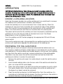
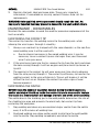
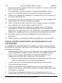
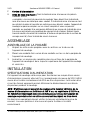
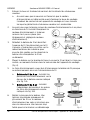
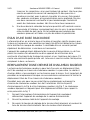
ALIGN AND SET THE DRIVE ROLLER
The correct drive roller grove must be set on the wire drive mechanism before
the welding wire is installed in the unit.
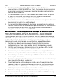
1. Open the door to the welding unit’s drive compartment.
2. Remove the drive tension by loosening the drive tension adjusting knob
(Fig. 2-1) and lifting the drive tension adjustor away from the drive tension
arm (Fig. 2-2). Pull the drive tension arm away from the drive roller.

8976052 MINIMIG 100E Flux-Cored Welder V4.0
14 For technical questions call 1-800-665-8685
3. If there is a wire already installed in the welding unit, roll it back onto the
wire spool by hand-turning the spool counterclockwise. Be careful not to
allow the wire to come out of the rear end of the inlet guide tube (Fig. 2-3)
without holding onto it or it will unspool itself. Put the end of the wire
into the hole on the outside edge of the wire spool and bend it over to
hold the wire in place. Remove the spool of wire from the drive
compartment of the welding unit.
4. Rotate the drive roller Cap (Fig. 2-4) counterclockwise and remove it from
the drive roller.
5. Pull the drive roller off the drive roller shaft.
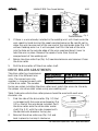
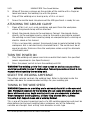
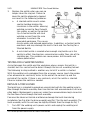
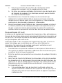
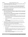
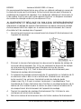
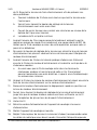
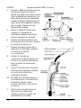
DRIVE ROLLER ADJUSTMENTS
The drive roller has two grooves
built into it for different wire
sizes. The correct wire size
number is stamped on each side
of the drive roller. The number
facing you when installing the drive roller must match the wire size. Use only
the proper size drive roller when using your welding unit.
Table 1 indicates which drive roller groove should be used with each wire
diameter size.
1. Find the side of the drive roller (Fig. 3-1) that
is stamped with the same wire diameter (Fig.
3-2) as that of the wire being installed. Push
the drive roller onto the drive roller motor
shaft (Fig. 3-3), with the side stamped with
the desired wire diameter facing you.
2. Reinstall the drive roller cap (Fig. 2-4) and
lock in place by turning it clockwise.
Wire Diameter
Drive Roller Groove
0.030 in. 0.030 in.
0.035 in. 0.035 in.
Fig. 2
Fig. 3

V4.0 MINIMIG 100E Flux-Cored Welder 8976052
Visit www.princessauto.com for more information 15
3. Close the door to the welding unit drive compartment.
SELECTING THE WELDING WIRE
The welding unit can handle different dimensions and types of welding wire.
Self-Shielding Flux-Core Wire - Four and eight-inch spools of 0.030 in.
(0.8 mm) or 0.035 in. (0.9 mm).
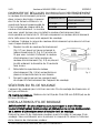
INSTALL THE WELDING WIRE
WARNING! Electric shock can kill! Always turn the power switch OFF and unplug
the power cord from the power source before installing the welding wire.
Remove old wire from the torch assembly before installing new welding wire. This
will help to prevent the possibility of the wire jamming inside the torch liner.
1. Remove the nozzle and contact tip from the end of the torch assembly.
a. Check that the power is OFF and
the power cord unplugged before
removing the welding nozzle. The
contact tip on this welding unit is
electrically hot whenever the
torch trigger is pulled.
2. Make sure the proper groove on the
drive roller is in place for the installed
wire. Change the drive roller if the
proper grove is not in place (see Align
and Set the Drive Roller).
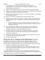
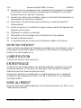
3. Unwrap the spool of wire and find the leading end of the wire. Do not
unhook it. The leading end goes through a hole in the outer edge of the
spool and is bent over the spool edge to
prevent the wire from unspooling.
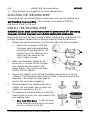
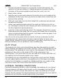
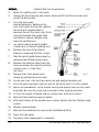
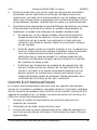
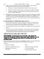
4. Place the spool on the spindle so the wire is
straight, not at an angle, when it enters the
welding unit mechanism (Fig. 4).
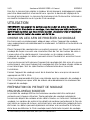
5. The purpose of the drive brake is to halt the
spool of wire at nearly the same moment that
wire feeding stops.
a. Four Inch Wire Spool - Install the drive
brake hardware on the top of the spool
of wire, as shown in Fig. 5-A.
A
B
Fig. 5
Fig. 4

8976052 MINIMIG 100E Flux-Cored Welder V4.0
16 For technical questions call 1-800-665-8685
b. Eight Inch Wire Spool - Install the spindle adapter and drive brake
hardware, as shown in Fig. 5-B.
6. Set the spool tension. Too much tension and the wire will slide on the
drive roller or the wire won’t feed into the mechanism. Tool little tension
and the wire may unspool itself. Readjust the drive brake tension to
correct for either problem.
a. Turn the wire spool with one hand and while adjusting the tension
with the other hand.
b. Tighten (turn clockwise) the drive tension adjustment knob with your
free hand.
c. Stop tightening when drag is felt on the wire spool that you are
turning.
d. The wire spool is ready for use.
7. Free the leading end of the wire from the spool and use wire cutters to
remove the bent portion, leaving a straight 90° cut. Do not let go of the
welding wire while doing this, as the wire may unspool itself.
8. Loosen the tension adjusting knob holding the drive tension arm in place
and lift the tension arm away from the driver roller.
9. Insert the leading end of the wire into the inlet guide tube. Then push the
wire across the drive roller and insert six inches into the torch assembly.
a. Make certain that the welding wire is actually going into the torch
liner and not alongside it. A misaligned wire may be deflected in
another direction and could damage the internal mechanisms.
10. Line the wire in the drive roller groove, then place the drive tension arm
on the drive roller.
11. Flip the quick release drive tensioner back up into position on the drive
tensioner arm.
12. Tighten (turn clockwise) the drive tension adjusting knob until the tension
roller is applying enough force on the wire to prevent it from slipping out
of the drive assembly.
13. Let go of the wire.
14. Connect the welding unit power cord to the power source.
15. Turn the welding unit ON.
16. Set the voltage switch to the voltage (heat) setting recommended for the
gauge metal that is to be welded. Refer to the label mounted on the cover,

V4.0 MINIMIG 100E Flux-Cored Welder 8976052
Visit www.princessauto.com for more information 17
inside the drive compartment, for recommended voltage (heat) settings
for your welding job.
17. Set the wire speed control to the middle of the wire speed range.
18. Straighten the torch cable and pull the trigger on the welding torch to
feed the wire through the torch assembly.
19. When at least an inch of wire sticks out past the end of the torch, release
the trigger.
20. Turn the power switch to the OFF position.
21. Select a contact tip stamped with the same diameter as the wire being
used. If stamped in metric, use Table 1.
a. A contact tip one size larger may be required if the wire jams due to
inherent variances in
flux-cored welding wire.
22. Slide the contact tip over the wire protruding from the end of the torch.
Thread the contact tip into the end of the torch and hand-tighten securely.
23. Install the nozzle on the torch assembly. For best results, coat the inside
of the nozzle with anti-stick spray or gel.
24 Cut off the excess wire that extends past the end of the nozzle, but leave
a short stub.
25. The wire feed is ready for use.
SET THE WIRE DRIVE TENSION
Prevent an arc flash from occurring during the process of setting the drive
tension, by not allowing the wire coming out of the torch to contact with the
workpiece, ground clamp or any grounded material.
1. Pull the trigger on the torch.
2. Turn the drive tension adjustment knob clockwise, increasing the drive
tension until the wire seems to feed smoothly without slipping.
The wire should not slip between the wire and the drive roller under normal
conditions. An obstruction in the wire feed path will cause the wire to slide on
the drive roller.
Once the tension is properly adjusted, the quick release drive tensioner may be
unlocked and relocked without readjusting the drive tension adjustment knob.
The wire drive tension will require a reset if the diameter or type of welding
wire is changed.

8976052 MINIMIG 100E Flux-Cored Welder V4.0
18 For technical questions call 1-800-665-8685
OPERATION
IMPORTANT! Metal thinner than 18 gauge cannot be welded with this
machine. Attempting to do so will cause burn through (blowing holes) in
the metal you are intending to weld. The maximum steel thickness that
shoudl be attempted is 1/4 in.
CHOOSE A WELDING LOCATION
Selecting the proper location to use the welding unit can significantly increase
the welding unit’s performance, reliability and lifespan.
Locate the welding unit in an environment that is clean and dry. Place the
welding unit to ensure free circulation of air around all sides of the welding
unit. Dust and dirt can accumulate on the moving parts of the welding unit.
Debris can retain moisture and that can increase wear for moving parts.
The power outlet used for the welding unit must be properly grounded and the
welding unit must be the only load on the electrical circuit. See Power
Requirements in the Installation section.
Turn the welding unit OFF before plugging into appropriate 120 volt 20 amp
power outlet.
The use of an extension cord is discouraged for arc welding machines. Extension
cord use will significantly degrade the performance of the welding unit.
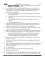
PREPARING THE MIG GUN/TORCH
The MIG gun or torch will require cleaning and preparation before each use.
Any previous welding will leave carbon deposits and molten bits on the nozzle
and welding tip. The metal beads and carbon deposits will disrupt the shielding
gas flow from the nozzle, resulting in uneven protection of the weld puddle.
The debris may also cause the nozzle to overheat and melt or distort the
welding wire before it reaches the weld point.
1. Remove the nozzle and inspect for molten beads inside the nozzle and on
the end.
2. Insert closed welding pliers into the rear end of the nozzle and rotate the
pliers to scrape off the metal beads.
3. Clean the carbon deposits on both the nozzle and welding tip with a cloth.
The metal should shine. Discard and replace the nozzle or welding tip if
the deposits or beads cannot be removed.
4. Treat the nozzle by dipping it in MIG Nozzle Dip. Twist the nozzle as it is
inserted up to the bevel into the grease. Continue twisting as the nozzle is
removed, leaving a coating of grease inside and out.

V4.0 MINIMIG 100E Flux-Cored Welder 8976052
Visit www.princessauto.com for more information 19
5. Wipe off the excess grease on the outside of the nozzle with a finger or
towel and cover the welding tip with the grease.
6. Snip off the welding wire, leaving only a 1/4 in. at most.
7. Screw the nozzle back into place and the MIG gun/torch is ready for use.
ATTACHING THE GROUND CLAMP
1. Clean off dirt, oil, rust, scale, oxidation and paint from the workpiece
where the ground clamp will be attached.
2. Attach the ground clamp to the workpiece. Connect the ground clamp
directly to the workpiece and as close to the weld as possible to prevent
the welding current from traveling along an unexpected path, creating an
electric shock or fire hazard.
If this is not possible, connect the ground clamp to metal attached to the
workpiece, but is not electrically insulated from it. The metal must be of
equal or greater thickness than the workpiece when using this alternate
attachment point.
TURN THE POWER ON
1. Plug the welding unit power cord into an outlet that meets the specified
power requirements (see Specifications).
2. Press the power switch to turn the welding unit ON.
WARNING! The welding unit is ‘live’ once turned on and can cause serious
electrical and burn injuries if mishandled. Take all precautions listed in this
manual when handling the welding unit.
SELECT THE WELDING AMPERAGE
The voltage selector controls the welding heat. Refer to the label inside the
welder side door for recommended settings for your welding job.
TUNING IN THE WIRE SPEED
WARNING! Exposure to a welding arc is extremely harmful to the eyes and
skin. Prolonged exposure to the welding arc can cause blindness and burns.
Never strike and arc or begin welding until you are adequately protected.
Wear flameproof welding gloves, a heavy long sleeved shirt, cuffless
trousers, high topped shoes and a welding helmet.
This is one of the most important parts of a MIG welding operation and must be
done before starting each welding job or whenever any of the following
variable are changes: heat setting, wire diameter or wire type.

8976052 MINIMIG 100E Flux-Cored Welder V4.0
20 For technical questions call 1-800-665-8685
1. Connect the ground clamp to a scrap piece of metal that matches the
material that you are welding. It should be equal to or greater than the
thickness of the actual workpiece and free of oil, paint, rust, etc.
2. Select a heat setting.
3. Hold the torch in one hand, allowing the nozzle to rest on the edge of the
workpiece farthest away from you and at an angle similar to one that will
be used when welding.
4. With your free hand, turn the Wire Speed Dial to maximum and continue
to hold onto the knob.
5. Lower your welding helmet and pull the trigger on the torch to start an
arc, then begin to drag the torch toward you while simultaneously turning
the Wire Speed dial counterclockwise.
6. Listen for a high–pitch buzzing sound. This indicates the setting is correct.
When decreasing the speed, the arc’s sound will change from a sputtering
noise to a high-pitched buzzing sound. It will begin sputtering again if you
decrease the wire speed too much.
You can use the wire speed control to slightly increase or decrease the heat
and penetration for a given heat setting by selecting higher or lower wire
speed settings. Repeat this tune-in procedure if you select a new heat setting, a
different diameter wire or a different type of welding wire.
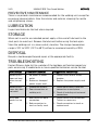
DUTY CYCLE
The welding unit’s duty cycle rating defines how long the operator can weld
before allowing the welding unit to cool. The duty cycle is a percentage of a 10-
minute period. The welding unit must cool for the remainder of the cycle. This
welding unit has a duty cycle rating of 20% at the rated output (see
Specifications). This means that the user can weld for 2 minutes and then rest
the welding unit for 8 minutes before using it again.
The welding unit may stop before the 2-minute duty cycle time limit. Reduce
the wire speed slightly and tune in the welding unit at the lowest wire speed
setting that still produces a smooth arc. Welding with the wire speed set too
high causes excessive current draw and shortens the duty cycle.
INTERNAL THERMAL PROTECTION
Constantly exceeding the duty cycle can damage the welding unit. An internal
thermal protector will open when the duty cycle is exceeded, shutting OFF all
welding unit functions except the cooling fan. Leave the welding unit turned
ON with the fan running. The thermal protector will automatically reset and the
welding unit will function normally again once it has cooled.
La page est en cours de chargement...
La page est en cours de chargement...
La page est en cours de chargement...
La page est en cours de chargement...
La page est en cours de chargement...
La page est en cours de chargement...
La page est en cours de chargement...
La page est en cours de chargement...
La page est en cours de chargement...
La page est en cours de chargement...
La page est en cours de chargement...
La page est en cours de chargement...
La page est en cours de chargement...
La page est en cours de chargement...
La page est en cours de chargement...
La page est en cours de chargement...
La page est en cours de chargement...
La page est en cours de chargement...
La page est en cours de chargement...
La page est en cours de chargement...
La page est en cours de chargement...
La page est en cours de chargement...
La page est en cours de chargement...
La page est en cours de chargement...
La page est en cours de chargement...
La page est en cours de chargement...
La page est en cours de chargement...
La page est en cours de chargement...
La page est en cours de chargement...
La page est en cours de chargement...
La page est en cours de chargement...
La page est en cours de chargement...
La page est en cours de chargement...
La page est en cours de chargement...
La page est en cours de chargement...
La page est en cours de chargement...
La page est en cours de chargement...
La page est en cours de chargement...
La page est en cours de chargement...
La page est en cours de chargement...
La page est en cours de chargement...
La page est en cours de chargement...
La page est en cours de chargement...
La page est en cours de chargement...
La page est en cours de chargement...
La page est en cours de chargement...
La page est en cours de chargement...
La page est en cours de chargement...
-
 1
1
-
 2
2
-
 3
3
-
 4
4
-
 5
5
-
 6
6
-
 7
7
-
 8
8
-
 9
9
-
 10
10
-
 11
11
-
 12
12
-
 13
13
-
 14
14
-
 15
15
-
 16
16
-
 17
17
-
 18
18
-
 19
19
-
 20
20
-
 21
21
-
 22
22
-
 23
23
-
 24
24
-
 25
25
-
 26
26
-
 27
27
-
 28
28
-
 29
29
-
 30
30
-
 31
31
-
 32
32
-
 33
33
-
 34
34
-
 35
35
-
 36
36
-
 37
37
-
 38
38
-
 39
39
-
 40
40
-
 41
41
-
 42
42
-
 43
43
-
 44
44
-
 45
45
-
 46
46
-
 47
47
-
 48
48
-
 49
49
-
 50
50
-
 51
51
-
 52
52
-
 53
53
-
 54
54
-
 55
55
-
 56
56
-
 57
57
-
 58
58
-
 59
59
-
 60
60
-
 61
61
-
 62
62
-
 63
63
-
 64
64
-
 65
65
-
 66
66
-
 67
67
-
 68
68


Powerfist 8976052 Le manuel du propriétaire
- Catégorie
- Système de soudage
- Taper
- Le manuel du propriétaire
dans d''autres langues
- English: Powerfist 8976052 Owner's manual
Documents connexes
Autres documents
-
Power Fist 8785115 Manuel utilisateur
-
-
Power Fist 8785008 Manuel utilisateur
-
PROPOINT 8958696 Le manuel du propriétaire
-
-
-
-
 Tweco FABRICATOR 252i Mode d'emploi
-
ESAB FABRICATOR252i Manuel utilisateur
-
 Tweco FABRICATOR® 141i 3-IN-1 Multi Process Welding Systems Manuel utilisateur

