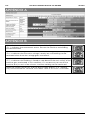
PROPOINT 8619470 Le manuel du propriétaire
- Catégorie
- Système de soudage
- Taper
- Le manuel du propriétaire

V1.0 8619470
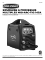
Please read and understand all instructions before use. Retain this manual for future reference.
145A MULTI-PROCESS
MIG-ARC-TIG WELDER
USER MANU
AL

8619470 145A MULTI-PROCESS MIG-ARC-TIG WELDER V1.0
2 For technical questions call 1-800-665-8685
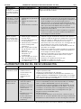
Specifications
SPECIFICATIONS
Input Voltage 115/230V AC
Input Current Rating 115V 16 to 21A
230V 16 to 27A
Phase Single
Output Current Range
10 to 145A
MIG (GMAW/FCAW) Welding Output @ 25% duty cycle 115V 30 to 80A
230V 30 to 145A
MIG Welding Voltage Range 15-1/2 to 21-1/2A
STICK (SMAW) Welding Output @ 25% duty cycle 115V 10 to 80A
230V 10 to 145A
TIG (GTAW) Welding Output @ 25% duty cycle
115V
10 to 80A
230V 10 to 145A
No-Load Voltage 53V
Welding Capacity 1/4 in.
Wire Feed Speed 60 to 630 in. per minute.
Welding Wire Diameter (MIG-ARC-TIG) 0.025/0.030/0.035 in.
Protection Class
IP21S
Compliance CAN/CSA
INTRODUCTION
The Pro.Point 145A Multi-Process MIG-ARC-TIG Welder incorporates the latest in IGBT technology
for maximum efficiency and longer duty cycles. The welding machine will provide 145 amps of MIG,
ARC and TIG output with dual voltage (115/230V). Settings are displayed on the digital LCD.
Choose manual or automatic control. Select the wire gauge and ARC/MIG/TIG with the
patented Smart-Set operation. The unit automatically adjusts the settings for optional welding.
For MIG/MAG welding, the user can choose gas or gasless options.
The welding unit has a Tweco euro style MIG Torch connection and the machine comes standard
with a Tweco 2 style torch. Inside are wire feeders with steel guide rollers for use with welding
wire. The unit includes both a hot start feature to boost electric arc ignition and an anti-stick
feature that cuts power to prevent overloads when the electrode sticks to the workpiece.
Compatible accessories include the MIG Welding Torch (SKU 8613002), the Multi-System TIG
Torch (SKU 8618456) and the 200A Spool Gun Kit (SKU 8612517).
SAFETY
WARNING! Read and understand all instructions before using this tool. The operator must follow
basic precautions to reduce the risk of personal injury and/or damage to the equipment.
Keep this manual for safety warnings, precautions, operating or inspection and maintenance
instructions.
145A MULTI-PROCESS
MIG-ARC-TIG WELDER

V1.0 145A MULTI-PROCESS MIG-ARC-TIG WELDER 8619470
Visit www.princessauto.com for more information 3
HAZARD DEFINITIONS
Please familiarize yourself with the hazard notices found in this manual. A notice is an alert that
there is a possibility of property damage, injury or death if certain instructions are not followed.
DANGER! This notice indicates an immediate and specific hazard that will result in severe
personal injury or death if the proper precautions are not taken.
WARNING! This notice indicates a specific hazard or unsafe practice that could result in
severe personal injury or death if the proper precautions are not taken.
CAUTION! This notice indicates a potentially hazardous situation that may result in minor or
moderate injury if proper practices are not taken.
NOTICE! This notice indicates that a specific hazard or unsafe practice will result in
equipment or property damage, but not personal injury.
WORK AREA
1. Operate in a safe work environment. Keep your work area clean, well-lit and free of distractions.
2. Remove all unnecessary people from the work area when welding. Anyone remaining in the
work area must wear the appropriate welding safety equipment.
3. Store tools properly in a safe and dry location. Keep tools out of the reach of children.
4. Do not weld on damp surfaces that can transmit the electric current.
5. Do not install or use in the presence of flammable gases, dust or liquids.
6. Welding sparks and ejected molten slag can start a fire. Remove combustible materials
within 39 ft (12 metres) of the welding unit. See Fire and Explosion Precautions.
7. Have a fire extinguisher readily available (see Fire and Explosion Precautions).
8. Use protective screens or barriers to protect others from flash and glare; warn others in the
area to look away from the arc.
9. Keep the welding unit at least one foot from any wall or structure.
10. Check that the work area is free from fires, sparks or hot debris before leaving.
WARNING! Wear personal protective equipment approved by the Canadian Standards
Association (CSA) or American National Standards Institute (ANSI).
HEAD PROTECTION
DANGER! Never look directly at the welding arc without the proper protection. The light can
cause flash burn damage and impair vision. Although treatment is possible, multiple
occurrences can result in permanent eye damage.
1. Protect your eyes from welding light by wearing a welder's helmet fitted with a filter shade
suitable for the type of welding you are doing. The welding process produces intense white
light, infrared and ultraviolet light, these arc rays can burn both eyes and skin.
1.1. Consult the Welding Shade Guide in Appendix A for the minimum shade to protect the
eyes based on the amperage and type of welding.
2. An opaque helmet will protect against the ultraviolet or infrared light. A helmet will also
protect against ejected hot material and slag. The helmet should protect the face, forehead,
ears and neck.
3. Wear a fire-resistant head covering like a skullcap or balaclava hood to protect your head
when the faceplate is down or when using a welding hand-held face shield.
4. Wear ventilated safety goggles beneath the welding helmet or behind the hand-held face
shield. The cooling weld bead may fragment or eject slag that can damage the eyes, when
the helmet or hand-held face shield is not in place.

8619470 145A MULTI-PROCESS MIG-ARC-TIG WELDER V1.0
4 For technical questions call 1-800-665-8685
4.1 Eye protection equipment should comply with CSA Z94.3-07 or ANSI Z87.1 standards
based on the type of work performed.
5. Wear fire resistant earplugs when welding overhead to prevent spatter or slag from falling
into ear.
PROTECTIVE CLOTHING
1. Wear a leather apron or jacket, leather welding gloves and full foot protection. Choose clothing
fabrics that resist sparks, heat, flames and splashes of molten material. Artificial fabrics may
burn and melt, resulting in a more severe injury.
1.1 Wear welding capes and sleeves when performing overhead welding.
2. Do not wear clothes or protective gear that are frayed, oily or greasy as they may ignite
from the heat or ejected slag and sparks.
3. Wear thick clothes that do not expose the skin. Ultraviolet or infrared light can burn skin
with sufficient exposure.
4. Do not wear clothing that can hold hot debris or sparks such as pant cuffs, shirt pockets or
boots. Choose clothing that has flaps over pockets or wear clothing to cover the openings such
as pant legs over the boots or an apron over the shirt.
5. Gloves shall should contain an insulating lining to protect against an electric shock.
6. Rubber soled footwear or electrically insulated work boots are recommended while
working with a welding unit. The non- skid sole is will also help maintain footing and
balance during work.
6.1 Select boots with steel toe protection to prevent injury from falling objects.
RESPIRATORS
1. Respiratory protection is needed when ventilation is not sufficient to remove welding fumes
or when there is risk of oxygen deficiency.
1.1. Wear a NIOSH approved respirator when working on materials that produce dust or
particulate matter.
2. Work in a confined space only if it is well ventilated or while wearing an air-supplied
respirator. Welding fumes and gases can displace air and lower the oxygen level causing
injury or death. Be sure the breathing air is safe (See Fumes and Gases).
3. The user can take the additional precaution of informing another person in the work area of
the potential danger, so that person can watch for indications that the user is suffering from
oxygen deprivation.
PERSONAL PRECAUTIONS
Control the tool, personal movement and the work environment to avoid personal injury or
damage to the tool.
1. Do not operate any tool when tired or under the influence of drugs, alcohol or medications.
2. Avoid wearing clothes or jewelry that can become entangled with the moving parts of a
tool. Keep long hair covered or bound.
3. Remove all jewelry or metal items from your person before welding. Metal items may
connect to the welding unit’s electrical circuit, causing an injury or death.
4. Do not overreach when operating the tool. Proper footing and balance enables better control
in unexpected situations.
5. Support the workpiece or clamp it to a stable platform. Holding the workpiece by hand or
against your body may lead to personal injury.
6. Do not wear any personal grooming products that are flammable, such as hair preparations,
perfume or cologne with an alcohol base.

V1.0 145A MULTI-PROCESS MIG-ARC-TIG WELDER 8619470
Visit www.princessauto.com for more information 5
7. Remove any combustibles, such as butane lighters or matches, from your person before
doing any welding. Hot welding sparks may light the matches or ignite leaking lighter fuel.
SPECIFIC SAFETY PRECAUTIONS
WARNING! DO NOT let comfort or familiarity with product (gained from repeated use)
replace strict adherence to the tool safety rules. If you use this tool unsafely or incorrectly,
you can suffer serious personal injury.
Welding produces sparks, molten slag, intense white light, plus infrared and ultraviolet light. A
cooling bead can eject chips or fragments of slag. Any of these can cause direct harm to the
eyes and skin of the welder or bystanders.
1. Use the correct tool for the job. This tool was designed for a specific function. Do not
modify or alter this tool or use it for an unintended purpose.
2. Arc welding requires the use a hand-held face shield or helmets with full face protection per
CSA standard Z94.3.1.
3. Protect against reflected arc rays. The rays can reflect off a shiny surfaces behind the user,
into the helmet and off the filter lens into the eyes. Remove or cover any reflective surface
behind the user such as a glossy painted surface, aluminum, stainless steel or glass.
4. Welding produces sparks and molten slag. A cooling bead can eject chips or fragments of
slag. Any of these can cause direct harm to the eyes or skin of the user or bystanders.
5. Erect protective screens or barriers to protect bystanders from the flash and glare; warn
others in the area not to watch the arc. Do not strike a welding arc until all bystanders and
you (the user) have welding shields and/or helmets in place.
6. Immediately replace a cracked or broken helmet or a scratched or damaged lens filter to
avoid damage to the eyes or face from arc flash or ejected molten material.
7. Do not allow the welding stick to accidentally touch the ground clamp or grounded work. An
arc flash will result from contact and can injury the unprepared user and bystanders.
8. Do not handle hot metal or electrode stubs with bare hands. Handling may result in a burn injury.
9. Do not use the welding unit if personal movement is confined or if there is a danger of falling.
10. Keep all panels and covers securely in place when operating the welding unit.
11. Insulate the ground clamp when not connected to a workpiece to prevent contact with any
metal object.
12. Do not operate the welding unit if the torch, electrode holder, welding cable or ground
cable are wet. Do not immerse them in water. These components and the welding unit must
be completely dry before attempting to use them.
13. Never dip the electrode in water for cooling.
14. Remove the electrode from the holder when not in use.
15. Do not point the torch or electrode holder at any body part of yourself or at anyone else.
16. Do not use a welding unit to thaw frozen pipes.
17. Insulate yourself from the work and the ground using dry insulation. Make certain that the
insulation is large enough to cover your full area of physical contact.
18. Remove the electrode from the holder when not in use.
19. When not welding, make certain that no part of the electrode circuit is touching the workpiece
or the ground. Accidental contact can cause overheating and create a fire hazard.
20. Maintain good ventilation of the louvers on this equipment. Good ventilation is of critical
importance for the normal performance and service life of this equipment.

8619470 145A MULTI-PROCESS MIG-ARC-TIG WELDER V1.0
6 For technical questions call 1-800-665-8685
21. When working above floor level, use a safety belt to protect yourself from a fall should you
get a shock.
22. The electrode, electrode reel, welding head, nozzle and semiautomatic welding guns are
electrically ‘hot’ when the welding unit is in semiautomatic or automatic wire welding mode.
23. When not welding, make certain that no part of the electrode circuit is touching the workpiece
or the ground. Accidental contact can cause overheating and create a fire hazard.
FIRE AND EXPLOSION PRECAUTIONS
Arc welding can produce sparks, hot slag or spatter, molten metal drops and hot metal parts
that can start fires.
1. Clear the floor and walls of an area of all combustible and/or flammable materials up to
39 ft (12 metres) away from the welding unit. Hot debris ejected during welding can land
at a considerable distance away. Solid floors of concrete or masonry is the preferred
working surface.
1.1 Cover any combustible material with fire resistant covers or shields, if it cannot be
removed. The covering must be tight and should not leave openings for sparks or
ejected slag to enter.
1.2. Check both sides of a panel or wall for combustible material. Remove the combustible
material before welding.
2. A combustible floor should be protected with a fire resistant covering. Alternatives are to
spray the floor with water to keep it wet for the duration of the welding or cover with damp
sand. Care must also be taken to avoid an electric shock when this is done. A combustible
floor directly laid onto concrete does not need to be sprayed with water.
3. Seal cracks and openings to adjacent areas that a spark or slag can enter. Seal any openings
found with a fire-resistant cover. Shut doors and windows that do not provide ventilation or
erect protective screens in front of them when possible.
4. Avoid welding near hydraulic lines or containers containing flammable contents.
5. Do not perform any welding work on containers that held flammable or toxic substance,
until they are cleaned by a person trained in removing toxic and flammable substances and
vapours per the American Welding Standard AWS F4.1.
6. Open a container before performing any welding work on it. The heat generated by the
welding process will cause the air and gases to expand. The internal pressure may cause a
sealed or closed container to rupture, possibly causing an injury or death.
7. Do not weld pipes or metal that are covered in combustible material or in contact with
combustible structure such as a wall. Only weld if the covering can be safely removed.
7.1 Follow all safety precautions and legal requirements before welding a workpiece that
contains Asbestos or attempting to remove the Asbestos covering. This requires expert
knowledge and equipment.
7.2 Molten slag can run down the inside and outside of a pipe and start a fire. Be aware
where the pipe terminates and take precautions.
8. Do not weld a panel that is a sandwich construction of combustible and metal materials.
9. Have a fire extinguisher available for immediate use. A dry chemical fire extinguisher for
Types A, B and C is suggested.
9.1 Welding a combustible metal like zinc, magnesium or titanium requires a Type D
fire extinguisher.
9.2 Do not use liquid based fire extinguishing methods near the electric arc welding unit, as
it may cause a shock hazard.
10. Ventilation systems should be positioned so sparks or molten slag isn’t carried to an
adjacent area.

V1.0 145A MULTI-PROCESS MIG-ARC-TIG WELDER 8619470
Visit www.princessauto.com for more information 7
11. Have a Fire Watcher observing areas outside of the welder’s view, such as the opposite side
of a wall or behind the welder. A fire may also start on the other side of a structure that
could not be removed. The Fire Watcher will extinguish a fire or raise the alarm to evacuate
if the fire cannot be contained by the extinguishing equipment.
11.1 A fire watch extends at least 30 minutes after the welding is complete to ensure there
are no fires caused by smoldering sparks or ejected material.
FUMES AND GASES
WARNING! Stop welding and move to a location with ventilation if your eyes, nose or throat
become irritated. This indicates the ventilation is not adequate to remove the fumes. Do not
resume welding until the ventilation is improved and the discomfort ceases. Seek medical
attention if the symptoms do not diminish or if the welder experiences nausea, dizziness
or malaise.
Welding may produce hazardous fumes and gas during the welding process. A well ventilated
work area can normally remove the fumes and gases, but sometimes the welding produces
fumes and gases that are hazardous to your health.
1. Only work in a confined space if the area is well ventilated or while wearing a respirator or
an air-supplied respirator. Welding fumes and gases can displace air and lower the oxygen
level causing injury or death. Be sure the breathing air is safe. Always have a trained
watchperson nearby.
1.1 If ventilation in the work area is poor, use an approved air-supplied respirator. All the
people in the work area must also have air-supplied respirators.
1.2 Oxygen displacement can occur in confined areas when the shielding gas fills the area
and pushes out air.
1.2.1 Argon, Propane and Carbon Dioxide are heavier than air and will fill a confined
space from the bottom up.
1.2.2 Helium and natural gas are lighter than air and will fill a confined space from the
top down.
2. Avoid positions that allow welding fumes to reach your face. Always attempt to weld ‘upwind’
of the workpiece with the airflow across the face of the welder. Airflow from behind may create
a low pressure area in front of the welder and draw the fumes to the person.
3. Ventilate the work area to remove welding fumes and gases. The fumes and gases should
be drawn away from the user.
3.1 Ventilation should be enough to disperse fumes, but not enough to disturb the
shielding gas or flame during welding.
3.2 Ventilation exhaust shall be directed to a non-work area to avoid exposing other people
to potential toxic or dangerous fumes.
3.3 Air removed from the work area by the ventilation system must be replenished with fresh
air to avoid oxygen starvation or a build-up of fumes or gases. Only use air to provide
ventilation. Any other combination of gases may be explosive or toxic to people in the
work area.
3.4 Ventilation methods that remove gas and fumes from the welding point before they
reach the welder’s face should be given preference.
4. Avoid welding in a work area that has vapours from cleaning, degreasing or any spraying
operations. The heat and light from welding can react with the vapour and form irritating or
potentially toxic gases. Wait for the vapours to disperse.
5. Consult the manufacturer's Safety Data Sheets (SDS) for instructions and precautions
about metals, consumables, coatings, cleaners and degreasers.

8619470 145A MULTI-PROCESS MIG-ARC-TIG WELDER V1.0
8 For technical questions call 1-800-665-8685
5.1 Do not weld on coated metals such as galvanized, lead or cadmium plated steel, unless
the coating is removed from the weld area. The coatings and any metals containing
these elements can give off toxic fumes during the welding process.
5.2 Do not weld, cut or heat lead, zinc, cadmium, mercury, beryllium or similar metals without
seeking professional advice and inspection of the welding area’s ventilation. These metals
produce extreme toxic fumes, which can cause discomfort, illness and death.
5.3 Do not weld or cut near chlorinated solvents or in areas that chlorinates solvents can
enter. The heat or ultraviolet light of the arc can separate chlorinated hydrocarbons into
a toxic gas (phosgene) that can poison or suffocate the user or bystanders.
6. Check the Safety Data Sheet for the proper handling and safety precautions for
consumable welding rods as the coating can have multiple chemicals.
COMPRESSED GAS CYLINDER PRECAUTIONS
WARNING! Improper handling or maintenance of compressed gas cylinders and regulators
can result in serious injury or death. Do not use a cylinder or its contents for anything other
than its intended use.
1. Only use inert or nonflammable gas with the welding unit such as Carbon Dioxide, Argon or
Helium with the welding unit.
1.1 Never use flammable gases. They will ignite and may result in an explosion or fire that can
cause death or injury.
2. Do not attempt to mix gases or refill a gas cylinder. Exchange a cylinder or have it refilled by a
professional service.
3. Do not deface or alter the name, number or other markings on a cylinder. Do not rely on a
cylinder’s colour to identify the contents. Do not connect a regulator to a cylinder that contains
a gas that the regulator was not designed to handle.
4. Do not expose a cylinder to excessive heat, sparks, slag, flame or any other heat source.
4.1 A cylinder exposed to temperatures above 130 °F will require water spray cooling.
This method may not be compatible with electric welding units due to the hazard
of electrocution.
5. Do not expose a cylinder to electricity of any kind.
6. Do not attempt to lubricate a regulator. Always change a cylinder carefully to prevent leaks
and damage to the cylinder’s walls, valve or safety devices.
7. Gases in the cylinder are under pressure. Protect the cylinder from bumps, falls, falling
objects and harsh weather. A punctured cylinder under pressure can become a lethal
projectile. If a cylinder is punctured, do not approach until all pressure is released.
7.1 Protect the valve and regulator. Damage to either can result in regulator’s explosive
ejection from the cylinder.
8. Always secure a gas cylinder in a vertical position to a welding cart or other fixed support
with a steel chain, so it cannot be knocked over.
8.1 Away from areas where they may be struck or subjected to physical damage.
8.2 A safe distance from arc welding or cutting operations and any other source of heat,
sparks or flame.
8.3 Do not use as an improvised support or roller.
9. Always place the cylinder cap securely on the cylinder unless it is in use or being serviced.
10. Do not use a wrench or hammer to open a cylinder valve that cannot be opened by hand.
Notify your supplier for instructions.

V1.0 145A MULTI-PROCESS MIG-ARC-TIG WELDER 8619470
Visit www.princessauto.com for more information 9
11. Do not modify or exchange gas cylinder fittings.
12. Close the cylinder valve and immediately remove the faulty regulator from service for
repair, if any of the following conditions exist:
12.1 Gas leaks externally.
12.2 Delivery pressure continues to rise with the downstream valve closed.
12.3 The gauge pointer does not move off the stop pin when pressurized or fails to return
to the stop pin after pressure is released.
13. Do not attempt to make regulator repairs. Send faulty regulators to the manufacturer's
designated repair center.
14. Do not weld on the gas cylinder.
15. Keep your head and face away from the cylinder valve outlet when opening the cylinder valve.
16. Compressed gas cylinders must not be located in a confined space with the person welding
to prevent the possibility of leaks displacing the oxygen.
ELECTRICAL SAFETY
1. Do not come into physical contact with the welding current circuit. The welding current
circuit includes:
1.1 The workpiece or any conductive material in contact with it.
1.2 The ground clamp.
1.3 The electrode or welding wire;
1.4 Any metal parts on the electrode holder or wire feed torch.
1.5 The output terminals.
2. Insulate yourself from the electrical current and ground using electrical insulating mats or
covers big enough to prevent physical contact with the workpiece or ground.
3. Connect the ground clamp as close to the welding area on the workpiece as practical to
prevent welding current from traveling along an unexpected path and causing an electric
shock or fire hazard.
3.1 An option is to attach the ground clamp to a bare metal spot on a metal workbench.
The circuit will complete as long as the workpiece is also in full contact with the bare
metal workbench.
4. Do not weld on damp surfaces that can transmit the electric current without taking
precautions for the welder and bystanders. The electrode, welding head and nozzle are
electrically ‘hot’.
5. Only use insulated connectors to join welding cables.
6. Ensure there are no contacts between the workpiece and work area that would allow it to
ground, other than through the ground cable circuit
7. Do not exceed the duty cycle or amperage required for the type of welding. Excessive
amperage can cause the deterioration of protective insulation and create a shock hazard.
8. Unplug the welding unit when not in use as the unit as current is still entering the unit, even
when it is turned off.
9. Frequently inspect input power cable for wear and tear, replace the cable immediately if
damaged. Bare wiring is dangerous and can kill.
10. Do not use damaged, under sized or badly joined cables.
11. Do not disconnect the power cord in place of using the ON/OFF switch on the tool. This will
prevent an accidental startup when the power cord is plugged into the power supply.

8619470 145A MULTI-PROCESS MIG-ARC-TIG WELDER V1.0
10 For technical questions call 1-800-665-8685
11.1 In the event of a power failure, turn off the machine as soon as the power is interrupted.
The possibility of accidental injury could occur, if the power returns and the unit is not
switched off.
12. Make certain the power source conforms to requirements of your equipment
(see Specifications).
POWER TOOL PRECAUTIONS
This equipment requires a dedicated 115/230 volt, 30 amp single-phase alternating current
circuit equipped with a similarly rated circuit breaker or slow blow fuse. Do not run other
appliances, lights, tools or equipment on the circuit while operating this welding unit.
1. Do not drape or carry coiled welding cables on your body while the cables are plugged into
the welding unit.
2. Do not start the tool when the electrode is touching the workpiece.
3. Hold the tool by the insulated gripping surfaces when performing an operation where it
may contact hidden wiring or its own cord and cables. Contact with a ‘live’ wire will
electrify exposed metal parts and shock the operator.
4. Take work breaks to prevent the tool's motor from overheating and/or overloading. Refer to
the welding unit’s duty cycle in Specifications.
5. Keep hands away from the electrode and the area it is being applied to when the tool is in
operation.
6. Do not connect the welding unit ground clamp to an electrical conduit. Do not weld on an
electrical conduit.
7. Do not touch the electrode or welded surface immediately after use. The surface will be hot
and may cause an injury.
8. Never use a tool with a cracked or worn electrode. Change the electrode before using and
discard the damaged one.
9. Remove the electrode from the holder when not in use.
POWER CORD
1. Insert the power cord plug directly to the power supply whenever possible. Extension cords
are not recommended for use with this welding unit.
1.1 When an extension cord is required, use a welding version that exceeds the welding
unit’s maximum power requirement.
2. Do not operate this tool if the power cord is frayed or damaged, as an electric shock or
surge may occur, resulting in personal injury or property damage.
2.1 Inspect the tool's power cord for cracks, fraying or other faults in the insulation or plug
before each use.
2.2 Discontinue use if a power cord feels more than comfortably warm while operating the
tool.
3. Keep all connections dry and off the ground to reduce the risk of electric shock. Do not
touch plug with wet hands.
4. Prevent damage to the power cord by observing the following:
4.1 Do not pull on the cord to disconnect the plug from an outlet.
4.2 Keep cord away from heat, oil, sharp edges or moving parts.
4.3 Place the electrical cord in a position that prevents it from contacting the tool or workpiece.
The cord should always stay behind the tool.

V1.0 145A MULTI-PROCESS MIG-ARC-TIG WELDER 8619470
Visit www.princessauto.com for more information 11
5. Make sure to locate the cord so that it is not stepped on, tripped over or otherwise subject
to damage or stress.
6. Do not wrap the cord around the tool, as sharp edges may cut insulation or cause cracks if
wound too tight. Gently coil cord and either hang on a hook or fasten with a device to keep
cord together during storage.
ELECTROMAGNETIC FIELDS
WARNING! Stop welding immediately and move away from the welding unit if you feel faint,
dizzy, nausea or shocks. Seek medical attention.
Electromagnetic Fields (EMF) can interfere with electronic devices such as pacemakers.
Anyone with a pacemaker should consult with their doctor before working with or near an arc
welding unit. The following steps can minimize the effects of electromagnetic fields.
1. Twist or tape cables together and prevent coils.
2. Do not drape cables on your body.
3. Keep the welding power source and cables as far away from the user as practical. A
minimum of 24 in. is recommended.
4. Connect the workpiece clamp as close to the weld as possible, but lay the electrode and
workpiece cables away from the user.
5. Use the lowest current setting possible during welding.
6. Avoid long and regular bursts of energy while welding. Apply the electrode in short strokes
and intermittently. This will prevent the pacemaker from interpreting the signal as a rapid
heartbeat.
7. Do not allow the electrode to touch the metal while welding.
8. Keep the lead cable and ground cables on the same side of your body.
9. Do not weld while carrying the welding power source.
10. Do not work next to, sit or lean on the welding power source.
UNPACKING
WARNING! Do not operate the tool if any part is missing. Replace the missing part before
operating. Failure to do so could result in a malfunction and personal injury.
Remove the parts and accessories from the packaging and inspect for damage. Make sure that
all items in the parts list are included.
Contents:
• 145 Multi-Process MIG-ARC-TIG Welding Unit
• Ground Lead and ARC Lead Set
• 2 V-Groove Drive Rollers, 0.6 to 0.8 mm and 0.8 to 1.0 mm
• MIG To rc h
• 115V/230V Adapter
• Regulator
The compatible MIG Welding Torch (SKU 8613002), Multi-System TIG Torch (SKU 8618456) and
200A Spool Gun Kit (SKU 8612517) are sold separately.

8619470 145A MULTI-PROCESS MIG-ARC-TIG WELDER V1.0
12 For technical questions call 1-800-665-8685
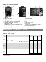
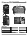
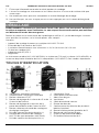
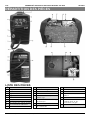
IDENTIFICATION KEY
A Digital Volts Meter
B Digital Amps Meter
C 2T/4T Selector Button
D Wire Speed / Amps Adjustment Knob
E Voltage / Downslope /ARC Force
Adjustment Knob
F Welding Mode / Smart-Set Selector Knob
G Negative Output Terminal (-)
H Euro MIG / TIG Torch Connector
(MIG/MAG)
I Positive Output Terminal (+)
J Dinse Connector
K Power Switch
L Gas Inlet
M Fan
N Input Power Cable
O Data Plate
P Spool Gun/Standard Selector Switch
Q Inch Wire Feed Button
R Gas Check Button
S Spool Holder Assembly
T Wire Feed Assembly
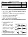
ASSEMBLY & INSTALLATION
Letter references in parenthesis (A) refer to the included Identification Key. Dashed numbers in
parenthesis (Fig. 1-1) refer to specific point of an illustration or image
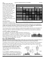
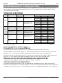
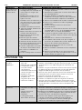
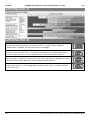
INPUT VOLTAGE
TYPE
INPUT
RATED CURRENT
OUTPUT
DUTY CYCLE
X
I2
U2
ARC
115V-20A 21.4A 10A/20.4V~80A/23.2V
25%
80A
23.2V
60%
52A
22.1.V
100%
40A
21.6
230V 27A 10A/20.4V~145A/25.8V
25%
145A
25.8V
60%
93.6A
23.7V
100%
72.5A
22.9V
MIG
115V-15A 21.4A 30A/15.5V~80A/18V
25%
80A
18V
60%
52A
16.6V
100%
40A
16V
230V 22.4A 30A/15.5V~145A/21.2V
25%
145A
21.2V
60%
93.6A
18.7V
100%
72.5A
17.6V
TIG
115V 16.5A 10A/10.4V~80A/13.2V
25%
80A
13.2V
60%
52A
12.1V
100%
40A
11.6V
230V 16.5A 10A/10.4V~145A/15.8V
25%
145A
15.8V
60%
93.6A
13.7V
100%
72.5A
12.9V
X = Duty cycle Percentage
I2 = Welding Current
U2 = Secondary Voltage with Welding Current I2
Fig. 1
Fig. 2
Fig. 3
Tabl e 1

V1.0 145A MULTI-PROCESS MIG-ARC-TIG WELDER 8619470
Visit www.princessauto.com for more information 13
TORCH POLARITY
Placement of the dinse connector (J) determines the torch’s polarity.
Straight Polarity or Torch Negative (-). Insert the dinse connector into the negative output
terminal (G). The torch has negative polarity in this configuration.
Reverse Polarity or Torch Positive (+). Insert the dinse connector into the positive output
terminal (I). The torch has positive polarity in this configuration.
INSTALLATION SET UP FOR ARC (STICK) WELDING
Please install the machine strictly according to the following steps.
POWER REQUIREMENTS
The power cord supplied with this welding unit is designed to handle the maximum power
required (see Specifications). Refer to the welding unit’s data plate and ensure the power
supply can meet those requirements.
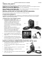
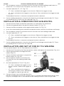
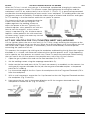
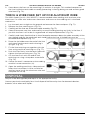
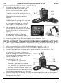
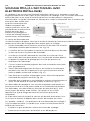
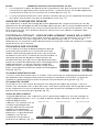
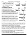
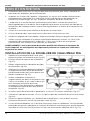
CONNECTING THE POWER LEADS
1. Connection of Output Cables - An
electrode may require either a positive or
a negative charge for optimum results.
Connect the electrode holder to the
Positive Outlet Socket (I) or Negative
Outlet Socket (G) based on the electrode
manufacturer’s information for the correct
polarity set up.
Figure 4 represents the default
configuration for ARC with the ground
lead connected to the negative lead
(Fig. 4-1) and the electrode holder
connected to the positive lead (Fig. 4-2).
The dinse connector remains unplugged.
2. Turn the power source on and select the
ARC function with the welding mode knob
(Fig. 4-3).
3. Set the welding current relevant to the
electrode type and size, as recommended
by the electrode manufacturer (Fig. 5)
4. Place the electrode into the electrode holder and clamp tight (Fig. 6).
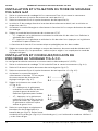
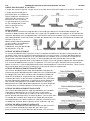
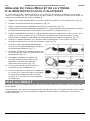
INSTALLATION & OPERATION FOR MIG WITH GAS
1. Connect the MIG Torch to the Euro connector (H)
and tighten the connector (Fig. 7-1).
2. Connect the ground lead to negative output socket
(G) (Fig. 7-2).
3. Connect the dinse connector (J) to positive outlet
socket (I) (Fig. 7-3).
4. Install the welding wire if needed (See Wire
Installation and Setup).
5. Open the valve on the gas cylinder and set the flow
to 21 CFH (Fig. 7-4).
7-4
7-2
7-1
7-5
7-7
7-3
7-6
Fig. 7
Fig. 4
4-3
4-1
4-2
Fig. 5
Fig. 6

8619470 145A MULTI-PROCESS MIG-ARC-TIG WELDER V1.0
14 For technical questions call 1-800-665-8685
6. Turn the power source on and select the MIG function with the welding mode knob. An
alternative is to use the Smart-Set option (see Smart-Set) (Fig. 7-6).
7. Set torch operation 2T / 4T (Fig. 7-5).
• 2T - Press and hold the trigger to start the arc. Release the trigger to stop.
• 4T - Press and release the trigger to start the arc. Press and release the trigger to stop
the arc.
The burnback function is automatic and preset for both selections.
8. Set the welding parameters using the wire feed (D) and voltage control knobs (E). These
will already be set if Smart-Set was selected (Fig. 7-7).
INSTALLATION & OPERATION FOR GASLESS MIG
1. Connect the MIG Torch to the Euro connector (H) and tighten the connector.
2. Connect the ground lead to the positive output socket (I) (Fig. 7-3).
3. Connect the dinse connector to the negative outlet socket (G) (Fig. 7-2).
4. Install flux-cored welding wire and the knurled drive roller (see Wire Installation and Setup).
5. Turn the power source on and select the MIG function with the welding mode knob.
6. Set torch operation 2T / 4T.
• 2T - Press and hold the trigger to start the arc. Release the trigger to stop.
• 4T - Press and release the trigger to start the arc. Press and release the trigger to stop
the arc.
The burnback function is automatic and preset for both selections.
7. Set the welding parameters using the wire feed (D) and voltage control knobs (E). These
will already be set if Smart-Set was selected.
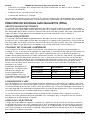
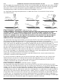
INSTALLATION AND SET UP FOR DC TIG WELDING
The set up described is for DC Electrode Positive (DCEP).
1. Connect the TIG torch to the Euro connection socket and tighten the connection (Fig. 8-4).
2. Connect ground lead to the negative outlet
socket (Fig. 8-3).
3. Connect the dinse connector (J) to positive
output socket (G) (Fig. 8-5).
4. Turn the power source on and select the
TIG function with the welding mode knob
(Fig. 8-7).
5. Set torch operation to 2T or 4T (Fig. 8-6).
• 2T - Press and hold the trigger to start
the gas and arc. Release the trigger to
stop.
• 4T - Press and release the trigger to
start the gas and arc. Press and release
the trigger to stop the gas and arc.
6. Connect the gas hose to the regulator then
connect the regulator to the gas cylinder (Fig. 8-1). Connect the other end of the gas hose
(Fig. 8-2) to the gas inlet (L) on the rear of the welding machine. Check for gas leaks.
Fig. 8
8-1
8-2
8-3
8-4
8-5
8-6
8-7

V1.0 145A MULTI-PROCESS MIG-ARC-TIG WELDER 8619470
Visit www.princessauto.com for more information 15
CHECK FOR GAS LEAKAGE
Check for gas leakage after each time the welding unit is set up for TIG welding and at
regular intervals.
The recommended procedure is as follows:
1. Connect the regulator and gas hose assembly and then tighten all connectors and clamps.
2. Slowly open the cylinder valve.
3. Set the flow rate on the regulator to approximately 15 to 25 CFH.
4. Close the cylinder valve and pay attention to the needle indicator on the regulator’s
pressure gauge. If the needle drops away towards zero, there is a gas leak.
Sometimes a gas leak can be slow and difficult to identify. Leave the gas pressure in the
regulator and line for an extended time. Perform the test as above, but reduce the flow rate
to 16 to 21 CFH. Close the cylinder valve and check after a minimum of 15 minutes.
5. After confirming there is a loss of gas, check all connectors and clamps for leakage by
brushing or spraying with soapy water. Bubbles will appear at the leakage point.
6. Tighten clamps or fittings to eliminate gas leakage. Replace the clamps and fittings if this
fails to solve the problem.
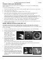
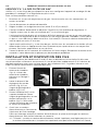
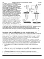
WIRE INSTALLATION AND SET UP
The correct installation of the wire spool and the wire into the wire feed unit is critical to
achieving an even and consistent wire feed. Poor set up of the wire into the wire feeder is a
major cause of fault with MIG welding machines. The guide below will assist in the correct setup
of your wire feeder.
1. Remove the spool retaining nut (Fig. 9). The spool retaining nut is left hand threaded.
2. Note the tension spring adjuster (Fig. 10-1) and spool locating pin (Fig. 10-2).
3. Fit the wire spool onto the
spool holder. Fit the
locating pin into the
location hole on the spool
(Fig. 11). Replace the spool
retaining nut tightly.
4. Choose a drive roller based
on the thickness of the
welding wire. Unscrew the
knob holding the drive
roller in place and exchange the drive rollers. Replace knob and tighten.
4.1 Flux-Cored – Install a knurled drive roller. Apply a light amount of pressure to the drive
roller. Too much pressure will crush the cored wire.
4.2 Aluminum - Install a U-groove drive roller.
5. Snip the wire carefully, be sure to hold the
wire to prevent the spool uncoiling. Carefully
feed the wire into the inlet guide tube of the
wire feed unit (Fig. 12).
6. Feed the wire through the drive roller and
into the outlet guide tube of the wire feeder
(Fig. 13-1). Note that the pressure roller in this
welding machine is smooth, not geared as in
the picture.
Fig. 9
Fig. 10
Fig. 11
10-2
10-1
Fig. 12
Fig. 13
13-1

8619470 145A MULTI-PROCESS MIG-ARC-TIG WELDER V1.0
16 For technical questions call 1-800-665-8685
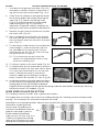
7. Lock down the top pressure roller (Fig. 14-1)
and apply a medium amount of pressure us-
ing the tension adjustment knob (Fig. 14-2).
8. Check that the wire passes through the center
of the outlet guide tube without touching the
sides (Fig. 15-1). Loosen the locking screw
(Fig. 15-2) and then loosen the outlet guide
tube retaining nut (Fig. 15-3) to make
adjustment if required. Carefully retighten the
locking nut and screw to hold the new position.
9. Remove the gas nozzle and contact tip from
the torch neck (Fig. 16)
10. Press and hold the inch button (Q) to feed
the wire through to the torch neck. Release
the inch button when the wire exits the torch
neck (Fig. 17).
11. Fit the correct sized contact tip and feed the
wire through it, screw the contact tip into
the tip holder of the torch head. Clip the
wire close to the tip (Fig. 18) unless testing
the drive tension in step 12.
11.1 Fit an aluminum contact tip of the
correct size and diameter when using
aluminum welding wire.
12. Fit the gas nozzle to the torch head (Fig. 19).
13. A simple check for the correct drive tension is
to bend the end of the wire over hold it about
4 in. from your hand and let it run into your
hand, it should coil round in your hand
without stopping and slipping at the drive
rollers, increase the tension if it slips (Fig. 20).
14. Insufficient tension on the wire spool can allow it
to spin after the wire feeding mechanism stops,
forcing loops of wire off the spool to become
tangled. Increase the pressure on the tension spring inside the spool holder assembly by adjusting
the tension screw if this happens (Fig. 21).
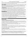
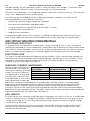
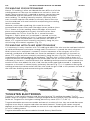
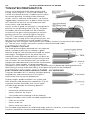
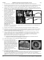
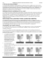
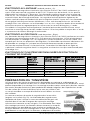
WIRE FEED ROLLER SELECTION
This welding machine includes two V-groove drive rollers.
The importance of smooth, consistent wire feeding during MIG welding cannot be emphasized
enough. The smoother the wire feed, the better the weld.
Feed rollers, also called drive rollers, feed the wire mechanically along the length of the welding gun.
Feed rollers are designed for
certain types of welding wire
and they have different types of
grooves machined in them to
accommodate the different
types of wire. The wire (Fig. 22-1)
is held in the groove by the top
roller of the wire drive unit and is
referred to as the pressure roller
V-Groove
U-Groove
Knurled-Groove
Fig. 22
22-1
22-2
Fig. 18
Fig. 19
Fig. 14
Fig. 15
15-3
15-2
14-2
14-1
15-1
Fig. 16
Fig. 17
Fig. 20
Fig. 21

V1.0 145A MULTI-PROCESS MIG-ARC-TIG WELDER 8619470
Visit www.princessauto.com for more information 17
(Fig. 22-2). Pressure is applied by a tension arm, which can be adjusted to increase or decrease the
pressure as required. The type of wire will determine how much pressure may be applied and what
type of drive roller is best suited to obtain optimum wire feed.
V-Shaped Groove - Solid hard wire, like steel or stainless steel, require a drive roller with a V-shape
groove for optimum grip and drive capability. Solid wires can have more tension applied to the wire
from the top pressure roller that holds the wire in the groove and the V shape groove is more
suited for this. Solid wires are more forgiving to feed due to their higher cross sectional column
strength. They are stiffer and do not easily bend.
U Shaped Groove - Soft wire, like Aluminum, requires a U-shape groove. Aluminum wire has
less column strength, can bend easily and is therefore more difficult to feed. Soft wires can
easily buckle at the wire feeder where the wire enters the torch’s inlet guide tube. The
U-shaped roller offers more surface area grip and traction to help feed the softer wire. Softer
wire also requires less tension from the top pressure roller to avoid deforming the wire’s shape.
Too much tension will push the wire out of shape and cause it to catch in the contact tip.
Knurled Drive Roller - Flux core/gasless wire is made of a thin metal sheath that has fluxing and
metal compounds layered onto it, which is then rolled into a cylinder to form the finished wire. The
wire cannot take too much pressure from the top roller, as it can be crushed and deformed. A
knurled drive roller was developed with small serrations in the groove. The serrations grip the wire
and assist to drive it without too much pressure from the top roller. The down side of using a
knurled wire feed roller with flux cored wire is it will slowly eat away at the surface of the welding
wire over time. These small bits eventually dislodge and go down into the liner. This will clog the
liner and the added friction will lead to welding wire feed problems.
A U-groove wire can also be used for flux core wire without the wire particles coming of the
wire surface. However, it is considered that the knurled roller will give a more positive feed of
flux core wire without any deformation of the wire shape.
OPERATION
FEATURES
THERMAL OVERLOAD PROTECTION
Constantly exceeding the duty cycle can damage the welding unit. An internal thermal protector
will open when the duty cycle is exceeded, shutting OFF all functions except the cooling fan. Leave
the welding unit turned ON with the fan running. The thermal protector will automatically reset and
the welding unit will function normally again once it has cooled.
Wait at least another 10 minutes after the thermal protector opens before resuming welding.
Starting before this additional time may result in a shortened duty cycle.
OVER-VOLTAGE
This equipment has an automatic voltage compensation function, which enables the unit to
maintain the voltage within the given range. In case that the input voltage or amperage exceeds
the stipulated value, it is possible to damage the equipment’s components. Please ensure your
primary power supply is correct (See Specifications).
DOWNSLOPE SETTING
Downslope is the gradual reduction of power to the electrical arc at the end of the welding
process. The power reduction allows the metal to cool more slowly and avoid a brittle weld or
stress cracks.
Downslope begins after releasing the torch trigger to shut off the welding arc. Power reduces
over a preselected time of 1 to 10 seconds (E). At the end of the selected duration, both the arc
and gas are stopped. The crater fill operation is automatic to factory-preset level.
IMPORTANT! This feature is only recommended for welding jobs that exceed 70 amps.

8619470 145A MULTI-PROCESS MIG-ARC-TIG WELDER V1.0
18 For technical questions call 1-800-665-8685
BURNBACK SETTING
Burnback is a feature that continues to supply power to the welding wire after the torch trigger
is release, but stops the welding wire from feeding. This provides time for the welder to remove
the welding wire from the weld pool before it solidifies. The setting is preset by the factory.
SMART-SET
Smart-Set uses pre-defined welding settings based on the type of Gas (Co2 or an Argon/Co2
mixture) and the wire diameter (0.030 or 0.035 in.). Turn the knob (F) to the selected pairing
and Smart-Set will configure the remaining parameters for optimal welding. You can begin
welding immediately.
WIRE FEED ON DEMAND
The welding unit has a feed-on-demand system to prevent wire waste. Initially the wire is slowly
fed through the torch, regardless of the set speed. Once an arc is struck, the unit feeds the wire
at the user’s selected speed.
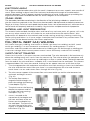
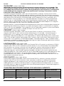
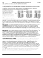
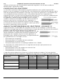
ARC (MANUAL METAL ARC) WELDING
One of the most common
types of arc welding is manual
metal arc welding (MMA) or
stick welding. An electric
current is used to strike an arc
between the base material
and a consumable electrode
rod or ‘stick’. The electrode
rod is made of a material that
is compatible with the base
material being welded and is covered with a flux that gives
off gaseous vapours that serve as a
shielding gas and providing a layer of slag, both of which protect the weld area
from
atmospheric contamination. The electrode core itself acts as filler material the residue from
the flux that forms a
slag covering over the weld metal must be chipped away after welding.
1. Strike the electrode on the workpiece to create the arc and hold the electrode steady to
maintain the arc (Fig. 24)
2. The heat of the arc melts the surface of the base metal to form a molten pool
at the end
of the electrode.
3. The melted electrode metal is transferred across the arc into the molten pool
and
becomes the deposited weld metal.
4.
The deposit is covered and protected by a slag, which comes from the
electrode
coating.
5.
The arc and immediate area are enveloped by an
atmosphere of
protective gas.
6. Hold the electrode slightly above the workpiece to
maintain the arc while travelling at an even speed
to create an even weld deposition (Fig. 25)
7. To finish the weld, break the arc by quickly
snapping the electrode away from the workpiece
(Fig. 26).
8. Wait for the weld to cool and carefully chip away the
slag to reveal the weld metal underneath (Fig. 27).
Manual metal arc (stick) electrodes have a solid
metal wire core and a flux
coating. These electrodes
Fig. 24
Fig. 25
Fig. 26
Fig. 27
Fig. 23

V1.0 145A MULTI-PROCESS MIG-ARC-TIG WELDER 8619470
Visit www.princessauto.com for more information 19
are identified by the wire diameter and by a series of letters and numbers. The letters and
numbers identify the metal
alloy and the intended use of the electrode.
The metal wire core works as a conductor of the current that maintains the arc.
The core wire
melts and is deposited into the welding pool.
The covering on a shielded metal arc welding electrode is called flux.
The flux on the
electrode performs many different functions:
• producing a protective gas around the weld area.
• providing fluxing elements and deoxidizers.
• creating a protective slag coating over the weld as it cools.
• establishing arc characteristics.
• adding alloying elements.
Covered electrodes serve many purposes in addition to adding filler metal to
the molten
pool. These additional functions are provided mainly by the
covering on the electrode.
ARC (STICK) WELDING FUNDAMENTALS
ELECTRODE SELECTION
As a general rule, the selection of an electrode is straight forward, in that it is only a matter of
selecting an electrode of similar composition to the parent metal. However, for some metals there
is a choice of several electrodes, each of which has particular properties to suit specific classes of
work. It is recommend to consult your welding supplier for the correct selection of electrode.
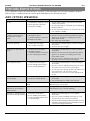
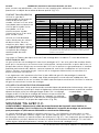
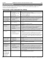
ELECTRODE SIZE
The size of the electrode generally depends on the thickness of the section being welded and
the thicker the section the larger the electrode required. The table gives the maximum size of
electrodes that may be used for various thicknesses of section based on using a general-
purpose type 6013 electrode (See Table 2).
WELDING CURRENT (AMPERAGE)
Correct current selection for a
particular job is an important
factor in arc welding. With the
current set too low, difficulty
is experienced in striking and
maintaining a stable arc. The
electrode tends to stick to the
work, penetration is poor and
beads with a distinct rounded profile will be deposited. Too high current is accompanied by
overheating of the electrode resulting undercut and burning through of the base metal and
producing excessive spatter. Normal current for a particular job may be considered as the
maximum, which can be used without burning through the work, over-heating the electrode or
producing a rough spattered surface. The table shows current ranges generally recommended for
a general-purpose type 6013 electrode (see Table 2).
ARC LENGTH
To strike the arc, the electrode should be gently scraped on the work until the arc is established.
There is a simple rule for the proper arc length; it should be the shortest arc that gives a good
surface to the weld. An arc too long reduces penetration, produces spatter and gives a rough
surface finish to the weld.
An excessively short arc will cause sticking of the electrode and result in poor quality welds.
General rule of thumb for down hand welding is to have an arc length no greater than the
diameter of the core wire.
Tabl e 2
AVERAGE THICKNESS
OF
MATERIAL
MAXIMUM RECOMMENDED
ELECTRODE DIAMETER
CURRENT RANGE
(AMPS)
0.03 to 0.07 in.
0.09 in.
60 to 100A
0.07 to 0.19 in. 0.12 in. 100 to 130A
0.19 to 0.31 in.
0.15 in.
130 to 165A
0.31 in. greater 0.19 in. 165 to 260A

8619470 145A MULTI-PROCESS MIG-ARC-TIG WELDER V1.0
20 For technical questions call 1-800-665-8685
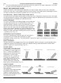
ELECTRODE ANGLE
The angle that the electrode makes with the work is important to ensure a smooth, even transfer of
metal. When welding in down hand, fillet, horizontal or overhead the angle of the electrode is
generally between 5 and 15 degrees towards the direction of travel. When vertical up welding the
angle of the electrode should be between 80 and 90 degrees to the workpiece.
TRAVEL SPEED
The electrode should be moved along in the direction of the joint being welded at a speed that will
give the size of run required. At the same time, the electrode is fed downwards to keep the correct arc
length at all times. Excessive travel speeds lead to poor fusion, lack of penetration etc., while too slow a
rate of travel will frequently lead to arc instability, slag inclusions and poor mechanical properties.
MATERIAL AND JOINT PREPARATION
The material to be welded should be clean and free of any moisture, paint, oil, grease, mill scale,
rust or any other material that will hinder the arc and contaminate the weld material. Joint
preparation will depend on the method used include sawing, punching, shearing, machining,
flame cutting and others. In all cases, edges should be clean and free of any contaminates. The
type of joint will be determined by the chosen application.
MIG (METAL INERT GAS) WELDING
MIG (metal inert gas) welding, also known as GMAW (gas metal arc welding) or MAG (metal
active gas welding), is a semi-automatic or automatic arc welding process in which a
continuous and consumable wire electrode and a shielding gas are fed through a welding gun.
A constant voltage, direct current power source is most commonly used with MIG welding.
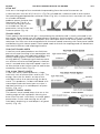
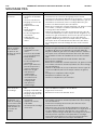
SHORT-CIRCUIT TRANSFER
Short-circuit transfer is the most common used method. The wire electrode is fed continuously
down the welding torch until it exits from the contact tip. The wire touches the workpiece and
causes a short-circuit. The wire heats up and begins to form a molten bead. The bead separates
from the end of the wire and forms a droplet that is transferred into the weld pool. This process
is repeated about 100 times per second, making the arc appear constant to the human eye.
1. The wire approaches the workpiece and touches the work creating a short-circuit between
the wire and the base metal, because there is no space between the wire and the base
metal there is no arc and current flows through the wire (Fig. 28)
2. The wire cannot support all the current flow, resistance builds up and the wire becomes hot
and weak and begins to melt
(Fig. 29)
3. The current flow creates a
magnetic field that begins to
pinch the melting wire forming
it into droplet (Fig. 30).
4. The pinch causes the forming
droplet to separate and fall
to-wards the now creating
weld pool (Fig. 31).
5. An arc is created at the
separation of the droplet and
the heat and force of the arc
flattens out the droplet into
the weld pool. The heat of the
arc melts the end of the wire
slightly as it feeds towards the
base metal (Fig. 32).
Fig. 31
Fig. 32
Fig. 33
Fig. 28
Fig. 29
Fig. 30
La page est en cours de chargement...
La page est en cours de chargement...
La page est en cours de chargement...
La page est en cours de chargement...
La page est en cours de chargement...
La page est en cours de chargement...
La page est en cours de chargement...
La page est en cours de chargement...
La page est en cours de chargement...
La page est en cours de chargement...
La page est en cours de chargement...
La page est en cours de chargement...
La page est en cours de chargement...
La page est en cours de chargement...
La page est en cours de chargement...
La page est en cours de chargement...
La page est en cours de chargement...
La page est en cours de chargement...
La page est en cours de chargement...
La page est en cours de chargement...
La page est en cours de chargement...
La page est en cours de chargement...
La page est en cours de chargement...
La page est en cours de chargement...
La page est en cours de chargement...
La page est en cours de chargement...
La page est en cours de chargement...
La page est en cours de chargement...
La page est en cours de chargement...
La page est en cours de chargement...
La page est en cours de chargement...
La page est en cours de chargement...
La page est en cours de chargement...
La page est en cours de chargement...
La page est en cours de chargement...
La page est en cours de chargement...
La page est en cours de chargement...
La page est en cours de chargement...
La page est en cours de chargement...
La page est en cours de chargement...
La page est en cours de chargement...
La page est en cours de chargement...
La page est en cours de chargement...
La page est en cours de chargement...
La page est en cours de chargement...
La page est en cours de chargement...
La page est en cours de chargement...
La page est en cours de chargement...
La page est en cours de chargement...
La page est en cours de chargement...
La page est en cours de chargement...
La page est en cours de chargement...
La page est en cours de chargement...
La page est en cours de chargement...
La page est en cours de chargement...
La page est en cours de chargement...
-
 1
1
-
 2
2
-
 3
3
-
 4
4
-
 5
5
-
 6
6
-
 7
7
-
 8
8
-
 9
9
-
 10
10
-
 11
11
-
 12
12
-
 13
13
-
 14
14
-
 15
15
-
 16
16
-
 17
17
-
 18
18
-
 19
19
-
 20
20
-
 21
21
-
 22
22
-
 23
23
-
 24
24
-
 25
25
-
 26
26
-
 27
27
-
 28
28
-
 29
29
-
 30
30
-
 31
31
-
 32
32
-
 33
33
-
 34
34
-
 35
35
-
 36
36
-
 37
37
-
 38
38
-
 39
39
-
 40
40
-
 41
41
-
 42
42
-
 43
43
-
 44
44
-
 45
45
-
 46
46
-
 47
47
-
 48
48
-
 49
49
-
 50
50
-
 51
51
-
 52
52
-
 53
53
-
 54
54
-
 55
55
-
 56
56
-
 57
57
-
 58
58
-
 59
59
-
 60
60
-
 61
61
-
 62
62
-
 63
63
-
 64
64
-
 65
65
-
 66
66
-
 67
67
-
 68
68
-
 69
69
-
 70
70
-
 71
71
-
 72
72
-
 73
73
-
 74
74
-
 75
75
-
 76
76


PROPOINT 8619470 Le manuel du propriétaire
- Catégorie
- Système de soudage
- Taper
- Le manuel du propriétaire
dans d''autres langues
- English: PROPOINT 8619470 Owner's manual
Documents connexes
-
PROPOINT 8611311 Le manuel du propriétaire
-
-
-
-
-
-
-
-
Autres documents
-
Powerfist 9038787 Le manuel du propriétaire
-
HobartWelders MULTI-HANDLER 200 Le manuel du propriétaire
-
-
Power Fist 8785115 Manuel utilisateur
-
Miller 190 Le manuel du propriétaire
-
-
 Tweco FABRICATOR® 141i 3-IN-1 Multi Process Welding Systems Manuel utilisateur
-
ESAB Firepower MST 140i 3-IN-1 Multi Process Welding System Manuel utilisateur
-
 Tweco FABRICATOR® 181i 3-IN-1 Multi Process Welding Systems Manuel utilisateur
-
 Tweco POWERMASTER® 350i/ 550i Multi Process Welding Inverter Manuel utilisateur


