ZIGBEE Smart Motion Sensor Manuel utilisateur
- Catégorie
- Cheminées
- Taper
- Manuel utilisateur

eng
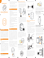
a.
d.
h.
b.
l.
c.
e.
f.
g.
j.
k.
m.
i.
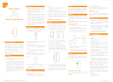
MOUNTING FLAT ON CEILING OR WALL
1. Remove the screw and open the casing by
pressing on the sides of the front cover while
pulling the back cover away. Use the sensor
part with oval holes to mark the screw
holes on the ceiling or the wall.
• Place the sensor indoors at a temperature
between 0-50°C.
• Its angle of detection from above, the sides,
and below must be 45°.
• Place the Motion Sensor 2 in a location with
a clear view of the monitored area and the
windows.
• The distance from the sensor to a replace
or a stove must be at least four meters.
• The Motion Sensor 2 must be reachable for
battery testing and maintenance.
• Place the sensor free of curtains and other
obstacles.
• Avoid placing the Motion Sensor 2 close to a
heating/cooling source.
• Avoid placing the Motion Sensor 2 in direct
sunlight or bright light.
Product description
The compact Motion Sensor 2 allows you to
detect if somebody is in the room or not. With
the Motion Sensor 2, you can set the light to
turn on and o as people come and go. The
motion sensor is PIR based and is able to sense
movement up to 9 meters from the sensor. It is
available with pet immunity & alarm certication.
Motion Sensor 2
Version 1.3
INSTALLATION MANUAL
Placement
CORNER OR CEILING MOUNTING WITH
CORNER BRACKET
1. If you have a sensor with a corner bracket
included, you can mount the sensor with
this bracket in a corner or on the ceiling.
2. Use the corner bracket to mark the screw
holes on the two walls in the corner of the
room or on the ceiling.
3. Use the two screws in the bag marked “A”
to install the bracket in the marked place.
Using screws for mounting is the most
secure mounting option, as it prevents
unwanted removal, e.g. by intruders.
Alternatively, you can use the two small, round
pieces of double adhesive tape to mount the
bracket in the corner (do not mount it on the
ceiling with tape). Make sure to press rmly on
the bracket with the tape to make it stick, and
then attach the sensor to the bracket.
Mounting
There are several mounting options for the
Motion Sensor 2. You can mount it at on a
ceiling or wall, using the screws, adhesive
tape, or magnet. If you have a sensor with a
corner bracket included, you can mount the
bracket in corners or on the ceiling, using
screws or adhesive tape. Afterwards, you can
attach the sensor to the bracket by using the
magnet inside the device or the screws. If you
have a stand included, you can also place the
sensor on the stand.
For pet immune motion sensors, it is important
that they are placed at 2.1 m / 6ft 10 inches
height (+/- 5 cm / 2 inches). Furthermore, it is
recommended to install pet immune motion
sensors in the corner of the room.
1. Before mounting: Remove the battery strip.
When mounting with a corner bracket, you have
two options for mounting the sensor on the
bracket: either with the magnet or screws.
MOUNTING THE SENSOR ON THE CORNER
BRACKET WITH THE SCREWS
If you are using the sensor for security purposes,
we recommend using screws to mount the
sensor on the bracket for a more secure fastening.
1. Remove the screw and open the casing by
pressing on the sides of the front cover while
pulling it apart from the back cover (see g. b).
2. Place the part with oval holes against the
already mounted bracket.
MOUNTING WITH MAGNET
If your sensor includes a corner bracket, you
can mount the sensor at on the wall or ceiling,
using the magnet from the bracket.
1. Unscrew the small magnet from the bracket.
2. Screw the magnet on a ceiling or a wall.
MOUNTING THE SENSOR ON THE CORNER
BRACKET WITH THE MAGNET
1. Attach the sensor to the corner bracket,
which includes a magnet.
3. Attach the sensor to the magnet.
Precautions
• When mounting with tape, make sure the
surfaces are clean and dry.
2. Mount the sensor on the wall or the ceiling
by installing one screw from the bag
marked “A” through each oval hole. Using
screws for mounting is the most secure
mounting option, as it prevents sudden,
unwanted removal.
3. Take two screws from the bag marked “B”.
Mount one screw through each oval hole
and into two holes on the corner bracket.
Disclaimers
CAUTION:
• Choking hazard! Keep away from children.
Contains small parts.
• Please follow the guidelines thoroughly. The
Motion Sensor 2 is a preventive, informing
device, not a guarantee or insurance that
sucient warning or protection will be
provided, or that no property damage,
theft, injury, or any similar situation will
take place. Develco Products cannot be
held responsible in case any of the above-
mentioned situations occur.
• When mounting with tape, the room
temperature should ideally be between 21°
C and 38° C and minimum 16° C.
• Avoid mounting with tape on rough, porous
or bered materials such as wood or
cement, as they reduce the tape bond.
3. Close the casing of the sensor.
Alternatively, you can use the large, round
piece of double adhesive tape to mount
the sensor. Make sure to press rmly on the
sensor with the tape to make it stick, since it is
pressure-activated tape.

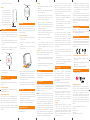
o.
p.
n.
q.
Develco Products assumes no responsibility for
any errors, which may appear in this manual.
Furthermore, Develco Products reserves the
right to alter the hardware, software, and/
or specications detailed herein at any time
without notice, and Develco Products does
not make any commitment to update the
information contained herein. All the trademarks
listed herein are owned by their respective
owners.
All rights reserved.
Other certications
• Zigbee 3.0 certied.
Disposal
Dispose the product and battery properly at the
end of their lives. This is electronic waste, which
should be recycled.
IN ACCORDANCE WITH THE DIRECTIVES
• Radio Equipment Directive (RED)
2014/53/EU
• RoHS Directive 2015/863/EU amending
2011/65/EU
• REACH 1907/2006/EU + 2016/1688
IC statement
Distributed by Develco Products A/S
Tangen 6
8200 Aarhus N
Denmark
www.develcoproducts.com
ISED statement
Innovation, Science and Economic
Development Canada ICES-003 Compliance
Label: CAN ICES-3 (B)/NMB-3(B).
ISED statement
The device will blink twice every minute when
the battery is low.
Battery replacement
Resetting
Resetting is needed if you want to connect your
Motion Sensor 2 to another gateway, or if you
need to perform a factory reset to eliminate
abnormal behaviour.
STEPS FOR RESETTING
1. Detach the sensor from the bracket and/or
open the casing.
2. Check that the batteries are inserted
correctly.
3. Press and hold the round menu button
inside the device.
4. While you are holding the button down, the
LED rst ashes once, then two times in a
row, and nally numerous times in a row.
5. Release the button while the LED is ashing
numerous times in a row.
6. After you release the button, the LED shows
one long ash, and the reset is completed.
Connecting
1. When batteries are connected, the Motion
Sensor 2 will automatically start searching
(up to 15 minutes) for a Zigbee network to
join.
2. Make sure that the Zigbee network is open
for joining devices and will accept the Motion
Sensor 2.
3. While the sensor is searching for a Zigbee
network to join, the LED ashes red.
Modes
SEARCHING GATEWAY MODE
Red LED light is ashing every second (up to 15
minutes).
LOW BATTERY MODE
The device will ash red twice every minute
when the battery is low.
ALARM TESTING MODE
The motion sensor will automatically ash
green every time movement is detected by the
Intruder Alarm System (IAS), no matter if the
alarm system is activated or deactivated. The
green ashes can help you determine if the
placement of the sensor is suitable for alarm
purposes.
STAND
1. If you have a sensor with
a plastic stand included,
you can insert the stand
in the opening on the
back of the sensor as
shown on the drawing.
2. Place the standing sensor
on the shelf or on a desk.
CE certication
The CE mark axed to this product conrms
its compliance with the European Directives
which apply to the product and, in particular, its
compliance with the harmonized standards and
specications.
Fault nding
• In case of a bad or weak signal, change the
location of the Motion Sensor 2. Otherwise,
you can relocate your gateway or strengthen
the signal with a smart plug.
• If the search for a gateway has timed out, a
short press on the button will restart it.
FCC statement
Changes or modications to the equipment not
expressly approved by the party responsible for
compliance could void the user’s authority to
operate the equipment.
NOTE: This equipment has been tested and
found to comply with the limits for a Class
B digital device, pursuant to Part 15 of the
FCC Rules. These limits are designed to
provide reasonable protection against harmful
interference in a residential installation. This
equipment generates, uses and can radiate radio
frequency energy and, if not installed and used
in accordance with the instructions, may cause
harmful interference to radio communications.
However, there is no guarantee that interference
will not occur in a particular installation.
4. When the sensor is connected to a network, it
will stop ashing.
If this equipment does cause harmful
interference to radio or television reception,
which can be determined by turning the
equipment o and on, the user is encouraged to
try to correct the interference by one or more of
the following measures:
• Reorient or relocate the receiving antenna.
• Increase the separation between the
equipment and receiver.
• Connect the equipment into an outlet on
a circuit dierent from that to which the
receiver is connected.
• Consult the dealer or an experienced radio/
TV technician for help.
This device complies with FCC RF radiation
exposure limits set forth for an uncontrolled
environment. The antenna used for this
transmitter must be installed to provide a
separation distance of at least 20 cm from
all persons and must not be co-located or
operating in conjunction with any other antenna
or transmitter.
This device complies with part 15 of the FCC
Rules. Operation is subject to the following two
conditions:
1. This device may not cause harmful
interference, and
2. This device must accept any interference
received, including interference that may
cause undesired operation.
Français
L’émetteur/récepteur exempt de licence
contenu dans le présent appareil est
conforme aux CNR d’Innovation, Sciences
et Développement économique Canada
applicables aux appareils radio exempts de
licence. L’exploitation est autorisée aux deux
conditions suivantes :
1. L’appareil ne doit pas produire de brouillage;
2. L’appareil doit accepter tout brouillage
radioélectrique subi, même si le brouillage
est susceptible d’en compromettre le
fonctionnement.
Cet équipement est conforme aux limites
d’exposition aux radiations IC CNR-102 établies
pour un environnement non contrôlé. Cet
équipement doit être installé et utilisé avec une
distance minimale de 20 cm entre le radiateur
et votre corps.
English
This device contains licence-exempt
transmitter(s)/receiver(s) that comply
with Innovation, Science and Economic
Development Canada’s licence-exempt
RSS(s). Operation is subject to the following
two conditions:
1. This device may not cause interference.
2. This device must accept any interference,
including interference that may cause
undesired operation of the device.
This equipment complies with IC RSS-102
radiation exposure limits set forth for an
uncontrolled environment. This equipment
should be installed and operated with
minimum distance 20 cm between the radiator
and your body.
4. Close the casing of the sensor. CAUTION:
• Do not attempt to recharge or open the
batteries.
• Risk of explosion if batteries are replaced
by an incorrect type.
• Dispose of a battery into re or a hot oven,
or mechanically crushing or cutting of a
battery can result in an explosion
• Leaving a battery in an extremely high
temperature surrounding environment can
result in an explosion or the leakage of
ammable liquid or gas.
• A battery subjected to extremely low air
pressure may result in an explosion or the
leakage of ammable liquid or gas
• Maximum operation temperature is 50°C /
122°F
• If you experience leakage from the
batteries, immediately wash your hands
and/or any aected area of your body
thoroughly!
CAUTION: When removing cover for battery
change - Electrostatic Discharge (ESD) can
harm electronic components inside
1. To replace the battery, detach the Motion
Sensor 2 from the bracket and/or open the
casing.
2. Replace the battery respecting the polarities.
3. Close the casing of the sensor.
-
 1
1
-
 2
2


ZIGBEE Smart Motion Sensor Manuel utilisateur
- Catégorie
- Cheminées
- Taper
- Manuel utilisateur
dans d''autres langues
Documents connexes
Autres documents
-
Develco Motion Sensor Manuel utilisateur
-
-
Develco WISZB-137 Manuel utilisateur
-
LEEDARSON CAG1a100015W7P Manuel utilisateur
-
Develco Products H6500113 Manuel utilisateur
-
Develco Products Entry Sensor Manuel utilisateur
-
Frient FRIZMOSZB-140 Zigbee Motion Sensor Pro Guide d'installation
-
Develco WISZB-134 Manuel utilisateur
-
 Develco Products WISZB-130 Guide d'installation
-
Develco Humidity Guide d'installation
