
DUTCHWEST
DUTCHWEST
4580
DW1000
COVER
Read this entire manual before you install and
use your appliance.
If not properly installed, a house fire may result.
To reduce the risk of fire, follow the installation
instructions.
Failure to follow instructions may result in prop-
erty damage, bodily injury or even death.
Contact local building, fire officials or authori-
ties having jurisdiction about permits, restric-
tions and installation inspection requirements in
your area.
This stove is listed by OMNI-Test Laboratories of Port-
land, Oregon to meet UL1482 for the US and ULC-627
for Canada
30004580 3/10 Rev. 5
This manual describes the installation and operation of the DW1000L02, DW1500L02
and DW2000L02 non-catalytic, wood heaters. This heater meets US Environmental
Protection Agency emission limits for wood heaters.

2
DW1000/15000/2000
30004580
After reading these instructions, if you have any doubt
about your ability to complete your installation in a
professional like manner you should obtain the services
of an installer versed in all aspects as to the correct
and safe installation. Do not use temporary makeshift
compromises during installation.
1. Check with the building inspector’s office for compli-
ance with local codes; a permit may be required.
2. This appliance requires a masonry or prefabricated
chimney listed to ULC S629 (Canada) and UL103HT
(U.S.). Sized correctly.
3. A 6” (152 mm) diameter flue is required for proper
performance.
4. Always connect this unit to a chimney and
vent to another room or inside a building.
5. connect this unit to any duct work to which
another appliance is connected such as a furnace.
6. connect this unit to a chimney flue serving
another appliance.
7. The connector pipe and chimney should be inspect-
ed periodically and cleaned if necessary.
8. Remember the clearance distances when you place
furniture or other objects within the area.
store wood, flammable liquids or other combustible
materials too close to the unit.
9. Contact your local municipal or provincial fire author-
ity for information on how to handle a chimney fire.
Have a clearly understood plan to handle a chimney
fire. In the event of a chimney fire, turn air control
to closed position and
10. tamper with combustion air control beyond
normal adjustment.
11. install these units in a mobile home or
trailer. These units are mobile home approved.
Draft is the force which moves air from the appliance
up through the chimney. The amount of draft in your
chimney depends on the length of the chimney, local
geography. Nearby obstructions, and other factors. Too
much draft may cause excessive temperatures in the
appliance. An uncontrolled burn or a glowing red part
or chimney connector indicates excessive draft. Inad-
equate draft may cause back puffing into the room and
“plugging” of the chimney and/or cause the appliance to
leak smoke into the room through appliance and chim-
ney connector joints.
Today’s solid fuel appliances are much more efficient
than in the past. The units are designed to give you
controlled combustion, as well as maximum heat trans-
fer, using less fuel to do so.
The design of your new appliance is such that the
exhaust “smoke” is now at lower temperatures than in
the past, therefore requiring proper chimney size to give
adequate draft. If your chimney is too large, the heating
appliance will have a difficult time to raise the “chim-
ney flue” temperature to give adequate draft, therefore
causing a smoke back up, poor burn or both.
With the door closed, the rate of burning is regulated by
the amount of air allowed to enter the unit through the
air control. With experience you will be able to set the
control for heat and burning time desired.
Once the required chimney draft is obtained, operate
only with doors closed and open doors slowly when
re-fueling. (This will reduce or eliminate smoke from
entering the room).
Attempts to achieve higher output rates that exceed
heater design specifications can result in permanent
damage to the heater. The recommended wood load is
level with the top of the firebricks.
Overloading may prevent sufficient air entering the
heater to properly fuel the fire.
Operate this heater only with the door closed.
Model S31105
120 V, 60 Hz, 0.75 Amps, 2900 rpm
Risk of Electric Shock.
Disconnect power before servicing unit.
For optimum heater performance at
“low” burn rate, operate the fan at low speed.

3
DW1000/1500/2000
30004580
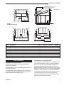
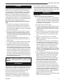
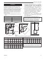
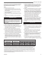
G
A
B
C
D
E
1056O”
(267 mm)
F
4580
dw1000 1500 dims
10/08
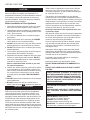
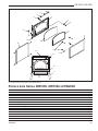
DW1000L02 29” 26C\v” 17Z\x” 20Z\x” 24C\,” 10C\v” 23C\v”
737 mm 679 mm 445 mm 521 mm 619 mm 273 mm 603 mm
DW1500L02 30” 27C\v” 17C\v” 22Z\v” 28C\v” 10C\v” 28Z\v”
762 mm 705 mm 450 mm 565 mm 730 mm 273 mm 718 mm
DW2000L02 31” 28C\v” 21M\,” 27” 26Z\x” 10C\v” 26Z\x”
787 mm 730 mm 556 mm 686 mm 673 mm 273 mm 667 mm
Figure 1
Stove Dimensions
Fuels used in gas, wood-
burning or oil fired appliances, and the products of
combustion of such fuels, contain chemicals known
to the State of California to cause cancer, birth de-
fects and other reproductive harm.
California Health & Safety Code Sec. 25249.6

4
DW1000/15000/2000
30004580
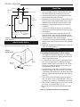
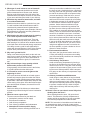
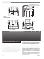
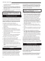
D
A
E
B
8”(203 mm)
*18” (457 mm)
8”
8”
F
C
F
S
IDE WALL
* CANADA **U.S.A
S
IDE
WA
L
L
**16” (406 mm)
BACK WALL
BACK WALL
C
&,//202/4%#4)/.
34
CLEARANCES
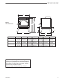
Figure 2
Clearance to Combustible Materials
1. Remove all parts from inside the stove body.
2. Select the proper location for the stove. These ap-
pliances must not be installed any closer than the
minimum clearance to combustible materials. (Fig.
2) The stove must be installed on a noncombustible
surface as shown on Page 7, Figure 4.
3. If noncombustible materials have been installed on
the walls, obtain the minimum clearances from either
the manufacturer of these materials or the local
building inspector’s office.
4. Install the refractory bricks. (Fig. 3)
5. Install the stovepipe INSIDE the flue collar on the top
of the stove between the stove and chimney.
6. use a grate to elevate the fire.
Unit must be placed on a noncombustible floor protection
equivalent to 3/8” millboard. Floor protector must have min. R
value of .893. Consult your local building authorities for further
information.
Contact your local buildng inspector prior to installa-
tion. A permit may be required in your area.
This Homeowner’s Manual describes the instal-
lation and operation of the models: DW1000L02,
DW1500L02, DW2000L02 non-catalytic wood heater.
This heater meets US Environmental Protection Agen-
cy’s emission limts for wood heaters. Under specific
conditions this heater has been shown to deliver heat at
the rates shown in Chart
A B C D E F G
Single wall 12” 12Z\x” 7” 19Z\x” 15” 15” 56”
Connector (305) (318) (178) (405) (381) (381) (1422)
Double wall 8Z\x” 8” 5Z\x” 15Z\x” 10” 13” 56”
Connector (216) (203) (140) (394) (254) (330) (1422)
DW1000L02 10,600 to 26,100
DW1500L02 10,370 to 29,301
DW2000L02 12,000 to 55,100
A B C D E F G
Single wall 11Z\x” 9” 7” 21” 11Z\x” 18” 54Z\x”
Connector (292) (229) (178) (533) (292) (457) (1384)
Double wall 6” 6” 4” 15” 8” 14” 54Z\x”
Connector (152) (152) (102) (381) (203) (356) (1384)
G
34
CEILINGCLEARANCES
Ceiling
Floor
ST1033
ST1032
A B C D E F G
Single wall 15” 10” 9” 24Z\x” 13” 19Z\x” 54”
Connector (381) (254) (229) (822) (325) (495) (1372)
Double wall 14” 10” 8” 23” 13” 18” 54”
Connector (356) (254) (203) (584) (325) (457) (1372)

5
DW1000/1500/2000
30004580
3 3
3
3
1
1
1
1 1
4
2
1
1
1
1
2
6
3
3 3 3
1 1 1
1
1 1 4
6
5
2
1
1
2
1
1
ST1034
DW1000 brick install
10/08
1
1
8
1
1
7
7
1 1
1 1
1
7
7
6
2
1
1
1
1
1
1
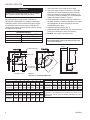
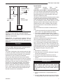
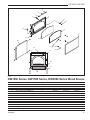
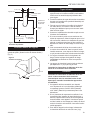
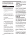
2 Full Bricks
(Be sure to install two (2) full
bricks in baffle as shown)
Baffle Assembly
ST1034
1. Firebrick Lt 9” x 4M\zn” x 1Z\v” (229 x 113 x 32 mm) S16040 11 12 15
2. Firebrick Angle Cut S16042 2 2 --
3. Firebrick Lt 7Z\v” x 4M\zn” x 1Z\v” (184 x 113 x 32 mm) S16043 4 4 --
4. Firebrick Lt 4Z\x” x 4M\zn” x 1Z\v” (114 x 113 x 32 mm) S16046 1 1 1
5. Firebrick Lt 2C\v” x 4M\zn” x 1Z\v” (70 x 113 x 32 mm) S16224 -- 1 --
6. Brick for Ash Drawer S16214 1 1 1
7. Firebrick Lt 7C\v” x 4M\zn” x 1Z\v” (197 x 113 x 32 mm) S16222 -- -- 4
8. Firebrick Lt 9” x 2Z\x” x 1Z\v” (229 x 64 x 32 mm) S16216 -- -- 1
Figure 3
Fire Brick Installation
An appliance mounted on a concrete floor does not
require floor protection.
Carpeting and any other combustible material shall not
cover Floor Protector.
If a combustible surface is applied to the concrete floor,
a clearance must be maintained equivalent to the area
reserved for the floor protector. (Fig. 4)
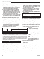
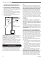
If the appliance is to be installed on a combustible floor
or a combustible floor covering, it must be installed on
a 3/8” (10 mm) thick noncombustible millboard floor
protector or durable equivalent. The pad must be in-
stalled beneath the appliance extending 18” (457 mm) in
Canada, 16” (406 mm) in the U.S. On any side equipped
with a door, and 8” (203 mm) on all other sides. In the
US, the pad must cover any horizontal chimney connec-
tor runs and extend 2” (51 mm) beyond each side.
A grouted ceramic floor-tile surface installed per local
building code considered equivalent.

6
DW1000/15000/2000
30004580
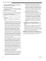
*16” (406 mm)
**18” (457 mm)
8”
(203 mm)
8”
(203 mm)
8” (203 mm)
ST1036
floor protection
10/08
2“ (51 mm) 2“ (51 mm)
Wall Line
Chimney Connector
Floor
Protector
Door Side of
Appliance
ST1036
Figure 4
Floor Protector
1. A clearance of 18” (457 mm) between the stovepipe
and combustible materials may be required. Check
with authorities having jurisdiction in your area.
2. All pipe sections must be connected with the male
end (crimped end) toward the stove.
3. Fasten the stove pipe to the flue collar by the use of
three (3) sheet metal screws. Do the same at each
additional joint to make the entire installation rigid.
4. Maintain the required diameter flue for the entire
installation.
5. If you are connecting the stove to an old masonry
flue, be sure to have it inspected for cracks and gen-
eral condition.
6. It is recommended that no more than two (2) 90°
bends be used in the stove pipe installation. More
than two (2) 90° bends may decrease the amount of
draw and possibly cause smoke spillage.
7. A damper is not required in this installation. Remove
damper plate in the chimney or secure in the OPEN
position.
8. Single wall flue pipe assemblies must not exceed 10
feet (3 m) in horizontal run.
1. This appliance requires a masonry or pre-manufac-
tured chimney listed to ULC S629 (Canada) and UL
103HT (US) sized correctly.
2. If a masonry chimney is used, it is advisable to have
your chimney inspected for cracks and check the
general condition before you install your unit. Relin-
ing may be required to reduce the flue diameter to
the appropriate functional size.
3. To help ensure a good draft, the top of the chimney
should be at least 3 feet (914 mm) above the point
of penetration through the roof, and be at least 2 feet
(610 mm) higher than any point of the roof within 10
feet (3 m).
4. The chimney connector shall not pass through an
attic, roof space, closet, concealed space, floor, ceil-
ing, wall or any partition of combustible construction.
5. The minimum overall height of your chimney should
be 15 feet (5 m) from the floor. (Fig. 6)
6. Do not use make shift compromises during installa-
tion.
Insert screw through handle holder and into lower left
side of stove (when facing the front). (Fig. )
34
HANDLEHOLDER
Handle
Mounting
Screw
Handle Holder
ST1038
Figure 5
Handle Holder

7
DW1000/1500/2000
30004580
34
CHIMNEYHEIGHT
3’ (1 m) Min.
from Roof
Penetration
15’ (5 m) Minimum
verall Height from
Floor
2’ (610 mm) Higher
than Nearest Point of
Roof within 10’ (3 m)
ST1037
Figure 6
Chimney height
open fire-door to a point where it
would be in contact with the combustible sidewall.
Brick for ash drawer must be installed before
operation of wood heater.
- An optional heat exchange blower is
available for this wood burning appliance. To order
please see the local dealer where you purchased your
apppliance.
Do not use a grate or elevate fire. Build wood fire
directly on hearth. When the stove is used for the first
time the solvents in the paint will smoke off.
This heater is designed to burn natural wood only. High-
er efficiency and lower emissions generally result when
burning air dried seasoned hardwood, as compared to
softwood or to green or freshly cut hardwood.
Only use dry seasoned wood. Green wood, besides
burning at only 60 percent of the fuel value of dry wood,
deposits creosote on the inside of your stove and along
the chimney. This can cause an extreme danger of
chimney fire. To be called “seasoned”, wood must be
dried for a year. Regardless of whether the wood is
green or seasoned, it should be stored in a well-shel-
tered, ventilated area to allow proper drying during the
year to come. Wood should be stored beyond recom-
mended clearance from combustibles.
Treated Wood Solvents Trash Coal
Garbage Cardboard Colored Paper
Your stove has been painted with the highest quality
stove paint and has special break-in procedures. The
heat generated by the normal operation of the stove,
will serve to harden the paint.
Ventilate the house during the first three times the stove
is used. The paint on the stove will give off smoke,
carbon dioxide and an odor. Without adequate ventila-
tion, concentrations of smoke could irritate you or cause
damage to person and/or property. Open doors and
windows and use a fan if necessary. After the initial
burns the paint will be cured and there should be no
more smoke.
Each of the initial burns should be conducted as fol-
lows:
1. The first and second burns should be approximately
250° F (120° C) for approximately 20 minutes.
2. The third burn should be between 500° F (260 to
370° C) for at least 45 minutes. The important fact is
the paint should be cured slowly. Avoid hot fires dur-
ing the curing process.
During the curing process the paint will be gummy.
Once cured the paint will remain hard.
It is normal to see flat spots on painted surfaces of the
stove. The flat spots on the paint surface indicate the
hotter surfaces of the stove, and is caused by the heat
radiating through the paint. It is also expected that shiny
spots caused by friction from the packaging materials,
will disappear during the curing of the stove.
SO:
1. Remember to ventilate well.
2. Allow the stove to cure before burning for long peri-
ods at high temperatures.
3. Flat spots on the painted surfaces are normal.
4. Shiny spots on the paint surface before burning is
normal.
5. Call your dealer if you have any questions.
1. Open inlet air control fully.
2. Place a small amount of crumpled paper in the
stove.
3. Cover the paper with a generous amount of kindling
in a teepee fashion and a few small pieces of wood.

8
DW1000/15000/2000
30004580
4. Ignite the paper and close door. If fire dies down
substantially, open door slightly.
5. Add larger pieces of wood as the fire progresses be-
ing careful not to overload. Do not fill firebox beyond
firebrick area. An ideal coal bed of 1” to 2” should be
established to achieve optimum performance.
6. This unit is designed to function most effectively
when air is allowed to circulate to all areas of the
firebox. An ideal means of achieving this is to rake a
slight (1” to 2” wide) trough in the center of the coal
bed from front to back prior to loading the fuel.
7. Once fuel has been loaded, close the door and open
air inlet control fully until fire is well established (ap-
prox. 10 minutes) being careful not to overfire.
8. Readjust air inlet control to desired burn rate. If
excessive smoke fills firebox, open air inlet control
slightly until flames resume and wood is sufficiently
ignited. While a basic rule of thumb is “closed-low”,
“1/2 way - medium” and “fully open-high”, refer to the
Inlet Air Control Settings chart.
9. When refueling, adjust air control to the fully open
position. When fire brightens, slowly and carefully
open the door. This procedure will prevent gases
from igniting causing smoke and flame spillage.
10.Add fuel being careful not to overload.
*1. Maximum burn times and heat outputs are based on laboratory testing using full loads of sea-
soned hardwoods, and may vary in individual use depending on how the stove is operated, type
and moisture content of fuel, and other factors. Maximum burn times are achieved under different
operating conditions than are maximum heat outputs.
2. These values are based on operation in building code conforming homes under typical winter
climate conditions in the northeastern US. If your home is of nonstandard construction (i.e. unusu-
ally well-insulated, built underground, or if you live in a more temperate climate), these may not
apply. Since so many variables affect performance, consult your Dutchwest Authorized Dealer to
determine realistic expectations for your home.
3. Under specific conditions used during EPA emission testing.
Low Closed Fully 10,600 10,370 12,000
Med / Low 1/4 Open 12,118 12,420 13,400
Med / High 3/4 Open 19,413 15,676 17,700
High Fully Open 26,100 29,301 55,100
The following use and safety tips should be observed.
1. Inspect the glass regularly for cracks and breaks. If
you detect a crack or break, extinguish the fire im-
mediately and contact your dealer for replacement.
2. Do not slam door or otherwise impact the glass.
When closing doors, make sure that logs or other
objects do not protrude and impact the glass.
3. Do not clean the glass with materials which may
scratch (or otherwise damage) the glass. Scratches
on the glass can develop into cracks or breaks.
4. Never attempt to clean the glass while unit is hot. If
the deposit is not very heavy, normal glass clean-
ers are adequate with a plain, nonabrasive scouring
pad. Heavier deposits may be removed with the use
of a readily available oven cleaner.
5. Never put substances which can ignite explosively
in the unit since even small explosions in confined
areas can blow out the glass.
6. This unit has an airwash system, designed to reduce
deposits on glass.
After extensive use, the sealing material which provides
glass and door seal may need to be replaced if it fails
to sustain its resilience. Inspect glass and door seal pe-
riodically to ensure for proper seal. If gaskets become
frayed or worn, replace immediately.
Contact your dealer for approved replacement parts.
The following steps should be followed for glass gasket
replacement:
1. Ensure appliance is not in operation and has thor-
oughly cooled.
2. Remove screw and glass clip.
3. Lift glass out from glass clip.
4. Remove old gasket and clean
glass.
5. Replace new gasket starting at the
bottom of glass working along edges,
being sure to center gasket channel
on glass.
6. Trim to length and butt ends to-
gether.
7. Replace glass in door, being sure
not to over-tighten screw and clip.
The following steps should be fol-
lowed for door gasket replacement:
1. Ensure appliance is not in operation and has thor-
oughly cooled.
2. Remove old door gasket and clean channel.
3. Using an approved high temperature gasket cement,
apply a thin coat in bottom of channel.
4. Starting at hinge side of door, work into around door
unit, and butt and trim to length.
5. Close door and allow three to four hours for cement
to set before restarting appliance.

9
DW1000/1500/2000
30004580
When wood is burned slowly, it produces tar and other
organic vapors. These combine with moisture to form
creosote. Creosote vapors condense in the relatively
cool chimney flue of a slow-burning fire. As a result,
creosote residue accumulates on the flue lining. When
ignited, this creosote makes an extremely hot fire.
The chimney should be inspected regularly during the
heating season to determine if a creosote build-up has
accumulated. If this is the case, the creosote should be
removed to reduce the risk of chimney fire.
1. Burn with air control open for several minutes at
numerous intervals throughout the day during the
heating season, being careful not to over-fire unit.
This removes the slight film of creosote accumulated
during low burn periods.
2. Burn stove with draft control wide open for several
minutes every time you apply fresh wood. This al-
lows wood to achieve the charcoal stage faster and
burns wood vapors which might otherwise be depos-
ited within the system.
3. Burn only seasoned wood. Avoid burning wet or
green wood. Seasoned wood has been dried for at
least one year.
4. A small hot fire is preferable to a large smouldering
one that can deposit creosote within the system.
5. Establish a routine for the fuel, wood burner and
firing technique. Check daily for creosote build-up
until experience shows how often you need to clean
to be safe. Be aware that the hotter the fire, the less
creosote is deposited. Weekly cleaning may be nec-
essary in mild weather even though monthly clean-
ing may be enough in the coldest months. Contact
your local municipal authority for information on how
to handle a chimney fire. Have a clearly understood
plan to handle a chimney fire.
This unit features a convenient ash lip for easy removal
of ash. During constant use, ashes should be removed
every few days, or whenever ashes get to three to four
inches deep in the firebox. Remove ashes only when
the fire has died down and the ashes have cooled.
Even then, expect to find a few hot embers.
Ashes should be placed in a metal container with a
tight-fitting lid. The closed container of ashes should
be placed on a noncombustible floor, well away from
a. You will need small pieces of dry wood (kindling)
and paper. Use only newspaper or paper that has
not been coated or had unknown materials glued
or applied to it. Never use coated (typically adver-
tising flyers) or colored paper.
b. Open the door of the wood stove.
c. Crumple several pieces of paper and place them
in the center of the firebox and directly on to the
firebricks of the wood stove. Never use a grate to
elevate the fire.
d. Place small pieces of dry wood kindling) over the
paper in a teepee manner. This allows for good
air circulation, which is critical for good combus-
tion.
e. Light the crumpled paper in 2 or 3 locations:
It is important to heat the air in the stove-
pipe for draft to start.
f. Fully open the air control of the wood stove and
close the door until it is slightly open, allowing
for much needed air to be introduced into the fire
box. Never leave the door fully open as sparks
from the kindling may occur causing injury or
property damage. As the fire begins to burn the
kindling, some additional kindling may be needed
to sustain the fire. add more paper after
the fire has started.
g. Once the kindling has started to burn, add some
of the smaller pieces of seasoned (dry) firewood.
Adding large pieces at the early stages
will only serve to smother the fire. Continue
adding small pieces of seasoned (dry) firewood,
keeping the door slightly open until each piece
starts to ignite. Remember to always open the
door slowly when placing wood into the fire.
h. Once the wood has started to ignite and the
smoke has reduced, close the wood stove door
fully. The reduction of smoke is a good indication
that the draft in the chimney has started and good
combustion is now possible. Larger pieces of
seasoned (dry) firewood can now be added when
there is sufficient space in the firebox. Adjust the
air control setting to desired setting.
i. The lower the air control setting the longer
the burn time of your firewood.
all combustible materials, pending final disposal. If
the ashes are disposed of by burial in soil or otherwise
locally dispersed, they should be retained in the closed
container until all cinders have thoroughly cooled. Other
waste should not be placed in the ash can.

10
DW1000/15000/2000
30004580
Dry seasoned hardwood should be used. Avoid
green unseasoned wood. Green wood, besides
burning at only 60 percent of the fuel value of dry
seasoned wood, will deposit creosote on the inside
of your stove and along the inside of your chimney.
Wood that has been dried for a period of one year
in a well-ventilated and sheltered area would be
considered dry seasoned wood. Hardwoods are
generally from slow growth trees (Example: Oak and
fir) Softwoods are generally from fast growth trees.
(Example: Pine and spruce).
The quick answer is most of the time. There are
many variables that may affect your success rate
when starting a fire. Most of those variables and how
to deal with them will be learned through experience.
Your ability to start a good fire will significantly in-
crease with time and patience. Some of the reasons
for poor stove performance will be covered next.
Damp or wet wood and poor draft are the main rea-
sons for poor results in starting a fire. Always use dry
seasoned wood for your fire. Even wood dried for
two years will be difficult to ignite, if it has become
wet.
A large quantity of thick black smoke in the firebox,
is a good indication that the draft is poor.
Your stove has been built with an air wash system
that will help keep the glass clear when the firebox
has reached a good operating temperature and has
a good draft. Cold firebox temperature and poor draft
cause sooting of the glass. Once the firebox temper-
ature and the draft increases, the soot will burn off.
Draft is the ability of the chimney to exhaust draw
by-products produced during the normal combustion
process.
The most common factors for poor draft are:
a. Atmospheric pressure and air supply
b. Environmental conditions
c. Cold chimney temperature
d. Poor chimney installation and maintenance
Atmospheric pressure affecting the draft from a
chimney can be either outside the home, inside
the home or both. Outside the home, a high-pres-
sure day (clear and cool) generally creates a bet-
ter draft in the chimney than a low-pressure day
(overcast and damp). Inside the home, normal
household appliances, such as clothes dryers
and forced air furnaces compete for air resulting
in inadequate amounts of air available to fuel a
fire and create a condition known as negative
pressure. Under extreme conditions of nega-
tive pressure the combustion by-products can
be drawn from the chimney and into the house.
This condition is commonly referred to as down
drafting. There are several factors that impact the
amount of air available in the home. Increased
amounts of insulation vinyl windows, extra caulk-
ing in various places and door seals can all keep
heat in but may also make a home too airtight.
If you are in doubt about whether or not there is
sufficient air in your home for your stove, curtail
using those appliances known to consume the
air where possible, or open a window or door to
allow air to enter the home.
High trees, low lying house location such as in
a valley, tall buildings or structures surrounding
your house and windy conditions can cause poor
draft or down drafting.
Avoid cold chimney temperatures by burning a
hot fire for the first fifteen to forty minutes, being
careful not to over fire. If any part of the chimney
or parts of the stove start to glow, you are over fir-
ing the stove. Where possible, install a tempera-
ture gauge on the chimney so temperature drops
can be seen.
Avoid using too many elbows or long horizontal
runs. If in doubt, contact a chimney expert and/or
chimney manufacturer for help. Clean chimney,
rain caps and especially spark arrester regularly,
to prevent creosote build up, which will signifi-
cantly reduce chimney draw and may cause a
chimney fire.
When shutting down the stove, fully open the air
control. This allows the chimney temperatures to
remain as high as possible for as long as possible.
Cold chimney temperatures create creosote.
This instruction is intended as an aid and does
not supersede any local, provincial or state require-
ments. Check with officials or authorities having jurisdic-
tion in your area.

11
DW1000/1500/2000
30004580
3
12
4
5
10
8
7
1
2
6
11
14
13
9
DUTCHWEST
19
15
18
17
16
15
DUTCHWEST
19
21
20
18
4580
DW1000/1500/2000
parts
10/08
20
MHSC reserves the right to make changes in design, materials, specifications, prices and discontinue colors and products at any time, without
notice.
1. Door Casting - Black 1 S12069 S12070 S12070
2. Glass Gasket 1 S31339 S31340 S31340
3. 1/8” (3 mm) Glass Gasket x 6’ 1 S15001-6 S15001-6 S15001-6
4. 5/8” (16 mm) Door Gasket x 6’ 1 S15011-6 S15011-6 S15011-6
5. Pawl Assembly 1 30002362 30002362 30002362
6. Handle - Black 1 1600664 1600664 1600664
7. Insert - Lifter Handle - Nickel 1 1600650 1600650 1600650
8. Screw 1/4 x 3C\,” 1 1201310 1201310 1201310
9. Handle Assembly 1 5004245 5004245 5004245
10. Lock Nut 1 1203290 1203290 1203290
11. Glass Clips 4 S37034 S37034 S37034
12. Screw #10 x 1/2 4 S11086 S11086 S11086
13. Hinge Pin 2 S11005 S11005 S11005
14. 3/8 Retaining Ring 2 S11090 S11090 S11090

12
DW1000/15000/2000
30004580
15. 1/4” Spring Handle 1 90000070 90000070 90000070
16. Ash Drawer 1 S31331 S31333 S31336
17. Leg Casting 2 S25076 S25080 S25084
18. Ashfender 1 S25077 S25082 S25082
19. Airmate 1 S25088 S25092 S25093
20. Removable Rear Heat Shield 1 90000037 90000038 S29265

13
DW1000/1500/2000
30004580
MHSC (hereafter referred to as the “company”) warrants that
your new Dutchwest brand wood burning plate steel stove or
masonry wood insert is free from manufacturing and material de-
fects for a period of three years from the date of sale, subject to
the following conditions and limitations.
Limited One Year Warranty
Electrical components such as blowers and speed controls are
covered for one year only. Glass door panels are covered for
thermal breakage only. To clean glass, use a ceramic glass
cleaner or polish. Do not use ammonia-based cleaners. A suit-
able cleaner is available from your nearest Hearth Products deal-
er. DO NOT CLEAN GLASS WHILE HOT AND DO NOT USE
ABRASIVE CLEANERS.
Brass parts should be cleaned with soap and warm water and
immediately dried. Brass parts may also be damaged by external
chemicals. Gold and any other plated parts will not be covered
under this warranty. Plated surfaces should be cleaned by using
denatured alcohol only and rubbed lightly with a lint-free non-
abrasive cloth. Excessive rubbing or polishing may remove the
plated finish. Discoloration of certain parts is normal and is not a
defect, and therefore not covered under warranty.
This warranty will not include or extend to paint, gaskets, baf-
fles or firebrick components, and does not cover any removable
firebox components such as brick retainers or stainless steel air
tubes.
The company offers a limited lifetime warranty on the firebox
(welds only), castings and ash drawers on any of Dutchwest
wood burning products. The limited lifetime warranty is extended
to the original owner only, and is subject to proof of purchase by
the original owner and residential use.
1. The new Dutchwest product must be installed and operated at all
times in accordance with the installation and operation instruc-
tions supplied with the appliance, and installation must be to local
and national codes. Any alterations, willful abuse, accident, over
firing or misuse will not be covered under warranty. NOTE: Some
minor movement of certain parts is normal and is not a defect
and therefore, not covered under warranty.
2. The warranty is non-transferable, and is made to the original
owner, provided that the purchase was made through an autho-
rized MHSC supplier. The serial number must be supplied along
with the Bill of Sale, showing the date of purchase, at the time the
claim is submitted.
3. This warranty is limited to the repair or replacement of parts
only and is applicable only to those parts found to be defective
in material or construction that have been subjected to normal
conditions of use and service. All defects must be confirmed by
the company or an authorized representative. If requested by the
company, defective parts must be shipped back transportation
prepaid, to the company. Credits will be issued upon receipt of
return of the defective product to the company.
4. The company, at its discretion, can fully discharge all obligation
with respect to this warranty by refunding the wholesale price of
the defective part(s).
5. Any installation, labor, construction, transportation or other re-
lated costs or expenses arising from defective parts, repair,
replacement or otherwise of same, will not be covered by this
warranty, nor will the company assume responsibility for same.
Further, the company will not be responsible for any incidental,
indirect or consequent damages, except as provided by law, and
in no event shall they exceed the original purchase price.
6. All other warranties - expressed or implied - with respect to the
product, its components and accessories, or any obligations /li-
abilities on the part of the company are hereby expressly ex-
cluded.
7. MHSC neither assumes, nor authorizes any third party to as-
sume, on MHSC’s behalf, any other liabilities with respect to the
sale of this MHSC product.
8. The warranties as outlined within this document do not apply to
chimney components or other products made by other manufac-
turers when used in conjunction with the installation of this prod-
uct. Improper use or the use of non-approved components may
nullify your warranty. If in doubt, contact your nearest authorized
MHSC supplier or MHSC Customer Service Department.
9. MHSC will not be responsible for:
• Down drafts or spillage caused by environmental conditions
such as near-by trees, buildings, rooftops, hills, mountains or
ineffective chimney design.
• Inadequate ventilation, excessive offsets or negative air
pressure caused by mechanical systems such as furnaces,
clothes dryers, fans, etc.
10. This warranty is void if:
• The appliance has been operated in atmospheres contami-
nated by chlorine, fluorine, or other damaging chemicals.
• This appliance has been subjected to prolonged periods of
dampness or condensation.
• The appliance has any damage due to water, or weather
damage that is the result of, but not limited to, improper chim-
ney/venting installation.
• The appliance has been subjected to willful or accidental
abuse or misuse.
• Corrosive driftwood, manufactured logs or other fuels are
used other than as outlined in the installation and operating
instructions.
• The appliance is not maintained in good condition, including
firebrick and gaskets.
Contact MHSC Customer Service. Make sure you have your
sales receipt and the model/serial number of your MHSC prod-
uct.
Do not attempt to do any service work yourself, unless pre-ap-
proved by MHSC in writing this will void the warranty.
MHSC must authorize service and provide a Warranty Claim
Number prior to any warranty related service calls. Without an
authorization number, any service work will not be deemed war-
ranty.
Some states and provinces do not allow the exclusion
or limitation of incidental or consequential damages. The above
limitation may not apply to you.
MHSC
149 Cleveland Drive
Paris, KY 40361
Serial # ________________Model # _____________________
Date Purchased ________________________

14
DW1000/15000/2000
30004580
DUTCHWEST
DUTCHWEST
4580
DW1000
COVER
Lisez le guide en entier avant d’installer et
d’utiliser votre pole.
Une installation inadquate pourrait occasion-
ner un incendie.
Pour diminuer le risque d’incendie, suivez les
instructions d’installation.
Tout manquement au respect de ces instruc-
tions pourrait donner lieu des dommages
votre proprit, des blessures corporelles ou
mme, dans des cas extrmes, causer la mort.
Communiquez avec votre directeur de la rgle
du btiment, du service permis, des restrictions
et des exigences d’inspection d’installation
dans votre rgion.
Ces appareils ne sont pas homologus pour
les maisons mobiles.
Cet appareil a t enregistr OMNI-Test Laboratories
of Portland, Oregon lte respectant ou dpassant les
normes UL1482 US et ULC-627 Canada
Nous recommandons que nos appareils de
chauffage au bois soient installs et entretenus
par des professionnels qui ont t accrdits aux
.-U. par le National Fireplace Institute® (NFI)
comme tant des spcialistes du NFI en mati
re d’appareils de chauffage au bois, ou qui sont
accrdits au Canada dans
le cadre du Programme de
formation technique en
nergie du bois (WETT).

15
DW1000/1500/2000
30004580
Aprs avoir lu ces instructions, si vous avez des doutes
quant votre capacit de faire toute l’installation d’une
manire professionnelle, vous devriez retenir les servic-
es d’un installateur qui s’y connat relativement tous
les aspects d’une installation la fois sre et correcte.
NE FAITES PAS de compromis temporaires lorsque
vous faites l’installation.
1. Assurez-vous avec le bureau de l’inspecteur des
btiments que votre installation respecte les codes
locaux; vous pourriez avoir besoin d’un permis pour
installer votre pole.
2. Cet appareil doit tre raccord une chemine en
maonnerie ou une chemine prfabrique portant
le numro ULC S629 (Canada) et UL 103HT (tats-
Unis) del la bonne dimension.
3. Il faut qu’un chemisage de chemine de six pouces
(152 mm) en acier inoxydable soit raccord ce po
le insr pour en tirer le meilleur rendement pos-
sible.
4. Raccordez toujours cet appareil une chemine
et ne permittez que les manations soliet
diriges vers une autre pice ou l’intrieur de
l’immeuble.
5. cette unit sur un autre syst
me de conduits auquel un autre appareil est rac-
cord, comme un four.
6. cet appareil sur une chemin
e dj raccorde sur un autre appareil.
7. Le tuyau de raccordement et la chemine doivent
tre inspects priodiquement et nettoys lorsque
c’est ncessaire.
8. Rappelez-vous les espaces de dgagement requis
lorsque vous placez des meubles ou d’autres objets
dans la pice. de bois, de
liquides inflammables ni d’autres matires combus-
tibles trop prs de votre appareil.
9. Communiquez avec vos autorits municipales ou
provinciales en matire d’incendie pour avoir des
infomations sur ce qu’il faut faire en cas d’incendie
de chemine. Ayez un plan bien arrt sur ce que
vous devez faire en cas d’incendie de chemine.
En cas d’incendie de chemine, fermez le contrle
d’admission d’air et
10. la commande d’admission
d’air au-del de son rglage normal.
11. N’installez pas cet appareil dans une maison mobile
ou dans une roulotte. Ces appareils NE SONT PAS
homologus pour les maisons mobiles.
Le tirage est le dplacement de l’air dans le conduit d’
vacuation et la chemine, vers l’exterieur. L’efficacit du
tirage dpend de la longueur de parcous entre l’appareil
et l’air libre, de facteurs gographiques, de la proximit
d’autres habitations, etc. Un tirage trop fort peut en-
trainer une temprature excessive dans l’appareil. Une
combustion non contrle ou le rougissement d’une
section de tuyau indique un excs de tirage. Un tirage
trop faible peut causer un refoulement de fume dans la
pice ou l’obstruction de la chemine et (ou) causer des
fuites de fume par les joints du conduit d’vacuation.
De nos jours, les appareils combustible solide sont
d’une grande efficacit. Les units sont conues pour
produire une combustion contrle et un maximum de
transfert de chaleur tout en utilisant moins de combus-
tible.
Votre appareil est fait pour vacuer la fume moins
chaude que par le pass; le diamtre de votre chemin
e est important pour obtenir un tirage adquat. Si votre
chemine est trop grande, l’appareil arrivera difficile-
ment en rchauffer l’intrieur pour obtenir un tirage
convenable; il y aura refoulement de fume ou combus-
tion trop faible ou les deux la fois.
Lorsque la porte est ferme, le taux de combustion est
dtermin par la quantit d’air pntrant dans l’appareil
par le volet d’admission d’air. Avec un peu d’expri-
ence, vous arriverez rgler le volet en fonction de la
chaleur et de la dure de combstions dsires.
Une fois obtenu le tirage de chemine requis, n’oprez
qu’avec la porte ferme et ouvrez lentement.
La porte lors du remplissage.
Toute tentative d’obtenir un taux de combstion dpas-
sant la limite pour laquelle l’appareil a t conu peut
entrainer un dommage permanent. La charge de bois
recommande correspond au remplissage jusqu’au
sommet des briques rfractaires. Trop mettre de bois
dans l’appareil. Cet appareil est conu pour fonctionner
porte ferme.

16
DW1000/15000/2000
30004580
Modle S31105
120 V, Frequ 60 Hz, 0,75 Amps 2900 RPM
Risque de secousse lectrique, dbran-
chez avant de procder a l’entretien.
Pour une meilleure performance de cet
appareil au “allumage bas” le ventilateur doit fonction-
ner a vitesse bas.
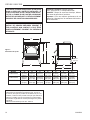
G
A
B
C
D
E
1056O”
(267 mm)
F
4580
dw1000 1500 dims
10/08
DW1000L02 737 mm 679 mm 445 mm 521 mm 619 mm 273 mm 603 mm
(29 po) (26C\v po) (17Z\x po) (20Z\x po) (24C\, po) (10C\v po) (23C\v po)
DW1500L02 762 mm 705 mm 450 mm 565 mm 730 mm 273 mm 718 mm
(30 po) (27C\v po) (17C\v po) (22Z\v po) (28C\v po) (10C\v po) (28Z\v po)
DW2000L02 787 mm 730 mm 556 mm 686 mm 673 mm 273 mm 667 mm
(31 po) (28C\v po) (21M\, po) (27 po) (26Z\x po) (10C\v po) (26Z\x po)
Figure 1
Dimensions du pole
267 mm
(10Z\x po)
Avertissement relatif la proposition 65 : Les combustibles
utiliss dans les appareils de chauffage au gaz, au bois ou
au mazout, ainsi que les produits de combustion de ces com-
bustibles, contiennent des produits chimiques que l’tat de la
Californie considre comme cancrognes et responsables
d’anomalies congnitales et d’autres pathologies du systme
reproductif.
California Health & Safety Code Sec. 25249.6

17
DW1000/1500/2000
30004580
Cette guide du propritaire dcrit l’installatin et
l’utilisation des modles DW1000L02, DW1500L02,
DW2000L02 de poles bois non catalytiques. Cet
appareil de chauffage rpond aux limites d’mission de
l’Agence pour la protection de l’environnement des
tats-Unis pour les poles bois. Dans des conditions
spciiques de fonctionnement, il a t dmontr que
l’appareil produit une puissance thermique allant de
tableau ci-dessous.
1. Retirez tous les composants placs l’intrieur du
pole.
Si vous ne respectez pas les distances de dégage-
ment minimales requises et ne disposez pas sur
une surface non combustible, votre installation
pourrait présenter des problémes de sécurité.
DW1000L02 10 600 26 100
DW1500L02 10 370 29 301
DW2000L02 12 000 55 100
2. Choisissez l’emplacement pour le poéle. Cet appar-
eil ne doit pas étre installé en-deéé des distances de
dégagement minimales é respecter par rapport aux
matiéres combustibles. Le poéle doit étre installé sur
une surface non combustible. (é la page 21, Fig. 4)
3. Si des matériaux non combustibles ont été installés
sur les murs, obtenez du fabricant de ces matériaux
ou du bureau local d’inspection des bétiments les
distances de dégagement minimales é respecter.
4. Installez des briques réfractaires. (Fig. 3)
5. Installez le tuyau é fumée é L’INTéRIEUR du collier
de la cheminée, sur le dessus du poéle poru relier le
poéle et la cheminée.
6. N’UTILISEZ PAS de chenets dans votre poéle.
D
A
E
B
8”(203 mm)
*18” (457 mm)
8”
8”
F
C
F
S
IDE WALL
* CANADA **U.S.A
S
IDE
WA
L
L
**16” (406 mm)
BACK WALL
BACK WALL
C
&,//202/4%#4)/.
34
CLEARANCES
Figure 2
Distance entre le pole et tout matriau combstible
Le pole doit tre install sur un plancher inflammable, quivalent
9,5 mm (3/8 po) “millboard”. Protecteur pour le plancher faut tre une
minimal R evaluer de .893. Informez vous auprs de l’inspecteur en
btiment de votre localit pour determiner si un permis est requis.
Distance entre le pole et tout matriau combstible
A B C D E F G
Connecteur 305 318 178 405 381 381 1422
paroi unique 12 po 12Z\x po 7 po 19Z\xpo 15 po 15 po 56 po
Connecteur 216 203 140 394 254 330 1422
double paroi 8Z\x po 8 po 5Z\x po 15Z\xpo 10 po 13 po 56 po
Distance entre le pole et tout matriau combstible
A B C D E F G
Connecteur 292 229 178 533 292 457 1384
paroi unique 11Z\x po 9 po 7 po 21 po 11Z\xpo 18 po 54Z\xpo
Connecteur 152 152 102 381 203 356 1384
double paroi 6 po 6 po 4 po 15 po 8 po 14 po 54Z\xpo
G
34
CEILINGCLEARANCES
Plancher
ST1033
ST1032
Distance entre le pole et tout matriau combstible
A B C D E F G
Connecteur 381 254 229 822 325 495 1372
paroi unique 15 po 10 po 9 po 24Z\xpo 13 po 19Z\xpo 54 po
Connecteur 356 254 203 584 325 457 1372
double paroi 14 po 10 po 8 po 23 po 13 po 18 po 54 po
Mur arrire
Mur arrire
Mur latral
Mur latral
Protecteur de
plancher
203 mm (8 po)
** 406 mm (16 po)
* 457 mm (18 po)
203 mm
(8 po)
203 mm
(8 po)
Plafond

18
DW1000/15000/2000
30004580
3 3
3
3
1
1
1
1 1
4
2
1
1
1
1
2
6
3
3 3 3
1 1 1
1
1 1 4
6
5
2
1
1
2
1
1
ST1034
DW1000 brick install
10/08
1
1
8
1
1
7
7
1 1
1 1
1
7
7
6
2
1
1
1
1
1
1
2 briques complte
(assurez-vous d’installer deux briques
compltes dans le dflecteur qu’indiqu
Dflecteur
ST1034
1. Brique rfractaire 229 x 113 x 32 mm (9 x 4M\zn x 1Z\v po S16040 11 12 15
2. Brique rfractaire couple angulaire S16042 2 2 --
3. Brique rfractaire 184 x 113 x 32 mm (7Z\v x 4M\zn x 1Z\v po) S16043 4 4 --
4. Brique rfractaire 114 x 113 x 32 mm (4Z\x x 4M\zn x 1Z\v po) S16046 1 1 1
5. Brique rfractaire 70 x 113 x 32 mm (2C\v x 4M\zn x 1Z\v po) S16224 -- 1 --
6. Brique pour tiroir cendres S16214 1 1 1
7. Brique rfractaire 197 x 113 x 32 mm (7C\v x 4M\zn x 1Z\v po) S16222 -- -- 4
8. Brique rfractaire 229 x 64 x 32 mm (9 x 2Z\x x 1Z\v po) S16216 -- -- 1
Figure 3
Fire Brick Installation
Il n’est pas ncessaire d’installer un revtement de
protection du plancher sous un appareil pos sur un
plancer en bton.
Le revtement de protection des planchers ne doit pas
tre recouvert de tapis ou autre matrial combustible.
Lorsqu’une surface combustible est pose sur un planc-
er en bton, il faut maintenir un dgagement quivalent
la zone rserve pour le revtement de protection des
planchers. voir le diagramme ci-dessous. (Fig. 4)
Si l’appareil est install sur un plancher combustible ou
un revtement de plancher combustible, il doit tre in-
stall sur un revtement de portection des planchers en
carton enroul non combustible pais ou un quivalent
durable. Le revtement doit tre install sous l’appareil
et dpasser de 457 mm (18 po) au Canada et de 16 po
(406 mm) aux tats-Unis de chaque ct domportant
une porte, et de 203 mm (8 po) des autres cts. Aux
tats-Unis, le revtement doit couvrir les tuyaux fum
e horizontaux et dpasser de 51 mm (2 po) de chaque
ct.
Un plancher en cramique jointoye install conform
ment au code du btiment local est considre comme
un quivalent durable.

19
DW1000/1500/2000
30004580
*16” (406 mm)
**18” (457 mm)
8”
(203 mm)
8”
(203 mm)
8” (203 mm)
ST1036
floor protection
10/08
2“ (51 mm) 2“ (51 mm)
Ligne du mur
Connecteur de la
chemine
Revtement
de protection
du plancher
Ct porte
de l’appareil
ST1036
Figure 4
Protection de plancher
203 mm (8 po)
203 mm
(8 po)
203 mm
(8 po)
** 406 mm (16 po)
* 457 mm (18 po)
51 mm (2 po)
51 mm (2 po)
Insrer la vis par le contrler le support et en bas
gauche de pole. (Quand on face au devent d’unite.)
(Fig. 5)
34
HANDLEHOLDER
Poigne
Vis de montage
Contrler le support
ST1038
Figure 5
Contrler le support
1. Prvoyez au moins 18 po de dgagement entre le
tuyau fume et les autres matraux combustibles.
Vrifier avec les autorits ayants juridiction dans
votre rgion.
2. Toutes les sections de tuyau doivent tre raccordes
de sorte que la partie mle (extrmit dentele) soit
oriente vers le pole.
3. Fixez le tuyau fume sur le collier de la chemin
e l’aide de trois vis mtal. Faites de mme
chaque joint additionnel pour que toute votre instal-
lation soit bien rigide.
4. Conservez le diamtre de chemine requis su toute
la hauteur de l’installation.
5. Si vous raccordez le pole sur une ancienne che-
mine de maonnerie, faites-la inspecter pour voir si
elle est fissure; obtenez une valuation de son tat
gnral; vous devrez peut-tre en faire modifier la
dimension l’aide d’un cheminsage en acier inoxyd-
able.
6. Il est recommand de limiter un maximum de 2
le nombre de coudes 90° dans le tuyau fume
install; autrement, vous risquez de rduire le tirage,
ce qui pourrait entraner des refoulements de fume.
7. Il n’est pas ncessaire d’avoir de rgulateur de
tirage. Retirez la plaque de rgulation du tirage
install dans la chemine ou fixez-la en position
OUVERTE.
8. Les tuyaux de chemine paroi simple ne doivent
pas dpasser 3 m (10 pi) de long au total.
1. Cet appareil doit tre raccord une chemin
e en maonnerie ou une chemine prfabriqu
e respectant la norme CanULC S629 (Canada)
et UL103HT (tats-Unis) notamment quant ses
dimensions.
2. Si une chemine de maonnerie est utilise, il est
conseill de faire inspecter la chemine de pour y
dceler la prsence de fissures et son tat gnral
avant d’installer votre appareil. Vous devrez peut-
tre faire installer un chemisage pour rduire le diam
tre de la chemine et la ramener une taille fonctiio-
nnelle approprie.
3. Pour aider obtgenir un bon tirage, le dessus de
la chemine doit tre au moins 914 mm (3 pi)

20
DW1000/15000/2000
30004580
au-dessus du point d’entre dans la toiture et au
moins (610 mm) 2 pi au-dessus de tout point de la
couverture situ dans un rayon de 3 m (10 pi).
4. Le connecteur de la chemine ne doit pas passer
travers un entre-toit, une garde-robe, un autre
espace cach similaire ou travers un plancher, un
plafond, un mur ou une cloison contenant des mat
riaux combustibles. (Fig. 6)
5. La hauteur hors tout minimale (pour les construc-
tions rsidentielles) de votre chemine devrait tre
de 5 m (15 pi) partir du plancher.
6. Ne faites pas de compromis temporaires lorsque
vous faites l’installation.
34
CHIMNEYHEIGHT
Hauteur mini-
male 1 m (3 pi)
au-dessus du
ont d’entre
dans la toiture
Hauteur minimale
5 m (15 pi) depuis
le plancher
hauteur minimale de 610 mm
(2 pi) au-dessus du point le
plus lev de la toiture sur un
rayon de 3 m (10 pi)
ST1037
Figure 6
Hauteur de la chemine
Ne pas ouvrir la porte pare-feu un
endroit o elle toucherait le mur latral combustible.
Une brique spciale pour le cendrier doit
tre installe avant l’utilisation du pole.
- Il est possible d’obtenir un venti-
lateur servant l’change de chaleur avec cet appareil
de chauffage au bois. Pour le commander, voyez le
distributeur local auprs de qui vous avez achet votre
appareil.
Cet appareil est conu pour la combustion de bois na-
turel seulement. On obtient le meileur rendement et le
minimum d’mission polluante en utilisant du bois franc
bien sec plutt que du bois mou ou du bois franc non
sch. N’utilisez que du bois bien sec. Le bois vert ne
produit que 60% du rendement en chaleur obtenu par
la combustion de bois sec; et le bois vert produit une
accumulation de crosote dans l’unit et sur la parol
intrieur de la chemine, ce qui prsente un fort danger
de feu de chemine. Pour tre sec, le bois doit avoir t
expos au grand air pendent une anne. De toute fa
on, vert ou sec, le bois doit tre abrit dans un endroit
bien ventil. Et le bois doit tre gard distance de tout
combustible.
• du bois trait • du charbon • des solvants • des
rebuts desordures • du carton • du papier color
Votre pole a t peinture avec une peinture de la plus
haute qualit pour les poles; cette peinture comporte
une procdure spciale de premire utilisation. La chal-
eur gnre par l’utilisation normale du pole servira
durcir la peinture.
Ventilez la maison au cours des trois premires fois
o vous utilisez le pole. La peinture applique sur le
pole mettra de la vume, du gaz carbonique et une
odeur. Sans ventilation adquate, les concentrations de
fume peuvent irriter, provoquer des blessures corpo-
relles et/ou des dommages votre proprite. Ouvrez
les portes et les fentres et, au besoin, utilisez un venti-
lateur. Une fois que vous aurez utilis votre pole poru
les premires fois, la peinture aura mri et il ne devrait
plus y avoir d’manations de fume.
Les premires utilisations de votre pole devraient se
faire comme suit :
1. Les deux premires utilisations devraient atteindre
environ 250 degrs F (120 degrs C) pendant envi-
ron 20 minutes.
2. La troisime utilisation devrait porter la temprature
500 degrs F (260 370 degrs C) pendant au
moins 45 minutes. Il faut que la peinture vieillisse
lentement. vitez les feux vifs pendant le vieillisse-
ment de la peinture.
Pendant le mrissement de la peinture, cette derni
re deviendra collante. Une fois qu’elle est mrie, la
peinture restera dure. Il est normal de voir des en-
droits mats sur les surfaces peintes de votre pole. les
endroits mats indiquen les surfaces les plus chaudes
de votre pole. Ces endroits mats proviennent de la
radiation de la chaleur travers la peinture. Il faut
galement s’attendre constter la prsence d’endroits
N’utilisez pas de grille dans le pole pour relever le feu.
tablissez votre feu directement sur le fond de la cham-
bre de combustion. Lorsque vous utilisez votre foyer
pour la premire fois, les solvants contenus dans le
peinture s’vaporeront en produisant un peu de fume.
La page est en cours de chargement...
La page est en cours de chargement...
La page est en cours de chargement...
La page est en cours de chargement...
La page est en cours de chargement...
La page est en cours de chargement...
La page est en cours de chargement...
La page est en cours de chargement...
-
 1
1
-
 2
2
-
 3
3
-
 4
4
-
 5
5
-
 6
6
-
 7
7
-
 8
8
-
 9
9
-
 10
10
-
 11
11
-
 12
12
-
 13
13
-
 14
14
-
 15
15
-
 16
16
-
 17
17
-
 18
18
-
 19
19
-
 20
20
-
 21
21
-
 22
22
-
 23
23
-
 24
24
-
 25
25
-
 26
26
-
 27
27
-
 28
28


DutchWest DW1000L02 Le manuel du propriétaire
- Catégorie
- Poêles
- Taper
- Le manuel du propriétaire
dans d''autres langues
- English: DutchWest DW1000L02 Owner's manual
Documents connexes
Autres documents
-
MHSC WR2000L02 Le manuel du propriétaire
-
Vermont Castings WR244 Le manuel du propriétaire
-
-
Superior Fireplaces WXS2000 Mode d'emploi
-
-
-