Porter Cable PCE980 Manuel utilisateur
- Catégorie
- Outils électroportatifs
- Taper
- Manuel utilisateur

final page size: 8.5 x 5.5 in
www.portercable.com
Instruction manual
Manuel d’instructions
Manual de’instrucciones
Thank you for choosing PORTER-CABLE! To register your new product, go to:
www.portercable.com/ServiceAndSupport/ProductRegistration.aspx
Merci d’avoir choisi PORTER-CABLE! Consulter le site Web www.portercable.com/ServiceAndSupport/
ProductRegistration.aspx pour enregistrer votre nouveau produit.
Gracias por elegir PORTER-CABLE usted! Para registrar su nuevo producto, visite: www.portercable.com /
ServiceAndSupport / ProductRegistration.aspx
INSTRUCTIVO DE OPERACIÓN, CENTROS DE SERVICIO Y PÓLIZA DE GARANTÍA.
ADVERTENCIA: LÉAS E ESTE INSTRUCTIVO ANTES DE USAR EL PRODUCTO.
Catalog Number
N° de catalogue
Catálogo N°
PCE980
6.5 Amp Wet Tile Saw
Scie pour carreaux à l’eau 6,5 A
Sierra para azulejos húmeda de 6.5 Amp

ENGLISH
English (original instructions) 1
Français (traduction de la notice d’instructions originale) 11
Español (traducido de las instrucciones originales) 22

ENGLISH
1
English (original instructions)
Definitions: Safety Alert Symbols and Words
This instruction manual uses the following safety alert symbols and words to alert you to hazardous situations and your risk
of personal injury or propertydamage.
DANGER: Indicates an imminently hazardous situation which, if not avoided, will result in death or seriousinjury.
WARNING: Indicates a potentially hazardous situation which, if not avoided, could result in death or seriousinjury.
CAUTION: Indicates a potentially hazardous situation which, if not avoided, may result in minor or moderateinjury.
(Used without word) Indicates a safety relatedmessage.
NOTICE: Indicates a practice not related to personal injury which, if not avoided, may result in propertydamage.
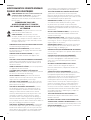
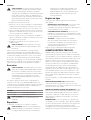
WARNING! Read all safety warnings and all
instructions. Failure to follow the warnings and
instructions may result in electric shock, fire and/or
seriousinjury.
WARNING: To reduce the risk of injury, read the
instructionmanual.
If you have any questions or comments about this or
any PORTER-CABLE tool, call us toll free at:
(888) 848-5175).
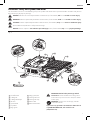
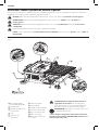
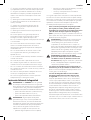
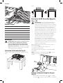
1
On/Off switch
2
Cutting cart
3
Cutting cart lock pin
4
Wrench
5
Splash hood
6
Flip hood
7
Edge guide
8
Edge guide lock
9
Cutting cart fence
10
Cutting cart stop
11
Power cord
12
Power cord retainer
Fig. A
1
11
2
6
12
7
3
8
9
10
5
4

ENGLISH
2
GENERAL POWER TOOL SAFETY WARNINGS
WARNING! Read all safety warnings and all
instructions. Failure to follow the warnings and
instructions may result in electric shock, fire and/or
seriousinjury.
SAVE ALL WARNINGS AND
INSTRUCTIONS FOR FUTURE
REFERENCE
The term “power tool” in the warnings refers to your mains-
operated (corded) power tool or battery-operated (cordless)
powertool.
WARNING: Never use saw with salt water or a
conductive fluid.
WARNING: when using electric tools, basic safety
precautions should always be followed to reduce risk
of fire, electric shock, and personal injury, including
the following:
• KEEP GUARDS IN PLACE and in working order.
• REMOVE ADJUSTING KEYS AND WRENCHES. Form
habit of checking to see that keys and adjusting wrenches
are removed from tool before turning it on.
• KEEP WORK AREA CLEAN. Cluttered areas and benches
invite injuries.
• DON’T USE IN DANGEROUS ENVIRONMENT. Don’t use
power tools in damp or wet locations, or expose them to
rain or snow. Keep work area well lighted.
• KEEP CHILDREN AWAY. All visitors should be kept safe
distance from work area.
• MAKE WORKSHOP KID PROOF with padlocks, master
switches, or by removing starter keys.
• DON’T FORCE TOOL. It will do the job better and safer at
the rate for which it was designed.
• USE RIGHT TOOL. Don’t force tool or attachment to do a
job for which it was not designed
• USE PROPER EXTENSION CORD. Make sure your
extension cord is in good condition. When using an
extension cord, be sure to use one heavy enough to carry
the current your product will draw. An undersized cord will
cause a drop in line voltage resulting in loss of power and
overheating. The following table shows the correct size
to use depending on cord length and nameplate ampere
rating. If in doubt, use the next heavier gage. The smaller
the gage number, the heavier the cord.
• WEAR PROPER APPAREL. Do not wear loose clothing,
gloves, neckties, rings, bracelets, or other jewelry which
may get caught in moving parts. Nonslip footwear is
recommended. Wear protective hair covering to contain
long hair. Air vents often cover moving parts and should
also be avoided.
• ALWAYS USE SAFETY GLASSES. Also use face or
dust mask if cutting operation is dusty. Everyday
eyeglasses only have impact resistant lenses, they are not
safetyglasses.
• SECURE WORK. Always place tile flat on cart and securely
against fence.
• NEVER USE A PAN HEATER OR OTHER HEAT SOURCE
FOR HEATING WATER. Damage to the tool, fire or
personal injury could result.
• DON’T OVERREACH. Keep proper footing and balance
at all times.
• MAINTAIN TOOLS WITH CARE. Keep tools sharp and
clean for best and safest performance. Follow instructions
for lubricating and changing accessories.
• DISCONNECT TOOLS before servicing; when changing
accessories, such as cutting wheels, clamps, extensions,
and thelike.
• REDUCE THE RISK OF UNINTENTIONAL STARTING.
Make sure switch is in off position before plugging in.
• USE RECOMMENDED ACCESSORIES. Consult the
instruction manual for recommended accessories. The use
of improper accessories may cause risk of injury to persons.
• NEVER STAND ON TOOL. Serious injury could
occur if the tool is tipped or if the cutting tool is
unintentionallycontacted.
• CHECK DAMAGED PARTS. Before further use of the tool,
a guard or other part that is damaged should be carefully
checked to determine that it will operate properly and
perform its intended function–check for alignment of
moving parts, binding of moving parts, breakage of parts,
mounting, and any other conditions that may affect its
operation. A guard or other part that is damaged should
be properly repaired or replaced.
• DIRECTION OF FEED. Feed work into a cutting wheel
with the direction of rotation only.
• NEVER LEAVE TOOL RUNNING UNATTENDED.
TURN POWER OFF. Don’t leave tool until it comes to a
completestop.
• REPLACEMENT PARTS. When servicing, use only
identical replacement parts.
Grounding Instructions
• In the event of a malfunction or breakdown, grounding
provides a path of least resistance for electric current to
reduce the risk of electric shock. This tool is equipped with
an electric cord having an equipment-grounding conductor
and a grounding plug. The plug must be plugged into a
matching outlet that is properly installed and grounded in
accordance with all local codes andordinances.
• Do not modify the plug provided – if it will not fit the outlet,
have the proper outlet installed by a qualifiedelectrician.
• Improper connection of the equipment-grounding
conductor can result in a risk of electric shock. The
conductor with insulation having an outer surface that
is green with or without yellow stripes is the equipment-
grounding conductor. If repair or replacement of the
electric cord or plug is necessary, do not connect the
equipment-grounding conductor to a liveterminal.
• Check with a qualified electrician or service personnel if
the grounding instructions are not completely understood,
or if in doubt as to whether the tool is properlygrounded.
• Use only 3-wire extension cords that have 3-prong grounding
plugs and 3-pole receptacles that accept the tool’splug.
• Repair or replace damaged or worn cordimmediately.
This tool should be grounded while in use to protect the
operator from electric shock. The tool is equipped with a

ENGLISH
3
3-conductor cord and 3-prong grounding type plug to fit
the proper grounding type receptacle. The green (or green
and yellow) conductor in the cord is the grounding wire.
Never connect the green (or green and yellow) wire to a live
terminal. If your unit is intended for use on less than 150 V,
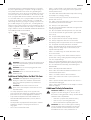
it has a plug that looks like that shown in sketch A. If it is for
use on 150 to 250 V, it has a plug that looks like that shown
in sketch D. An adapter, sketches B and C, is available for
connecting sketch A type plugs to 2-prong receptacles. The
green-colored rigid ear, lug, or the like, extending from the
adapter must be connected to a permanent ground, such as
a properly grounded outlet box. No adapter is available for a
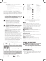
plug as shown in sketch D. ADAPTER SHOWN IN SKETCHES B
and C ARE NOT FOR USE INCANADA.
Fig. B
A B
GROUNDING PIN
GROUNDED
OUTLET
BOX
C D
GROUNDING
MEANS
GROUNDING PIN
ADAPTER
WARNING: To reduce the risk of electrocution, keep all
connections dry and off the ground. Do not touch the
plug with wethands.
WARNING: The saw must be plugged into a GFCI
protectedreceptacle.
WARNING: Never use saw with salt water or a
conductivefluid.
Additional Safety Rules for Wet Tile Saw
CAUTION: Wear appropriate hearing protection
during use. Under some conditions and duration
of use, noise from this product may contribute to
hearingloss.
CAUTION: Do not connect unit to electrical
power source until complete instructions are read
andunderstood.
• Use safety equipment. Always wear eye protection.
Dust mask, non-skid safety shoes, hard hat, or hearing
protection must be used for appropriateconditions.
• Keep hands out of path of saw blade. NEVER CUT A
PIECE WHERE HAND WOULD BE 3" (76mm) OR LESS
FROMBLADE.
• Do not perform any operation freehand, that is without
holding the workpiece firmly against the fence or
edgeguide.
• Never reach in back of theblade.
• DON’T - Cut dry. If blade is not cooled with water, serious
damage will occur. Dry cutting will increase exposure to
harmful airbornedust.
• Turn off the tool and wait for blade to stop before moving
the workpiece or changingsettings.
• To reduce risk of injury, return the cart to the full rear
position after eachcut.
• DO - Make certain the blade rotates in the correct direction
as indicated by the arrow on theblade.
• DO - Always use the splashhood.
• DO - Be sure all clamp handles and knobs are tight before
starting anyoperation.
• DO - Be sure all blade and clamp washers are clean and
recessed sides of collars are against blade. Tighten arbor
nutsecurely.
• DO - Keep the blade properlyaligned.
• DO - Keep the motor air slots free of chips anddirt.
• DO - Always empty water from the reservoir before
transporting. Water can splash into electricalcomponents.
• DO - Keep hands out of the path of the sawblade.
• DON’T - Attempt to operate on anything but designated
voltage. Incorrect voltage may result in shock, fire, or
unpredictableoperation.
• DON’T - Use blades larger or smaller than those which
arerecommended.
• DON’T - Force cutting action. Allow motor to reach full
speed before cutting. Stalling or partial stalling of motor
can cause majordamage.
• DON’T - Use metal cutting abrasive wheels. The excessive heat
and abrasive particles generated by them will damage thesaw.
• DO - Use continuous rim wheels only, no serrated edges or
toothedblades.
• DON’T - Allow anyone to stand behindsaw.
• DON’T - Place either hand in the blade area when the saw is
connected to the powersource.
• DON’T - Use blades rated less than 5000 R.P.M.
• DON’T - Place hands closer than 3" (76 mm) from the
sawblade.
• DON’T - Reach behind or underneath the saw unless it is
turned off andunplugged.
• DON’T - Move either hand from saw or workpiece until the
blade hasstopped.
Additional Safety Information
WARNING: ALWAYS use safety glasses. Everyday
eyeglasses are NOT safety glasses. Also use face or
dust mask if cutting operation is dusty. ALWAYS WEAR
CERTIFIED SAFETYEQUIPMENT:
• ANSI Z87.1 eye protection (CAN/CSA Z94.3),
• ANSI S12.6 (S3.19) hearing protection,
• NIOSH/OSHA/MSHA respiratoryprotection.
WARNING: Some dust created by power sanding,
sawing, grinding, drilling, and other construction
activities contains chemicals known to the State
of California to cause cancer, birth defects or

ENGLISH
4
other reproductive harm. Some examples of these
chemicalsare:
• lead from lead-based paints,
• crystalline silica from bricks and cement and other
masonry products, and
• arsenic and chromium from chemically-
treatedlumber.
Your risk from these exposures varies, depending on how
often you do this type of work. To reduce your exposure to
these chemicals: work in a well ventilated area, and work with
approved safety equipment, such as those dust masks that are
specially designed to filter out microscopicparticles.
• Avoid prolonged contact with dust from power
sanding, sawing, grinding, drilling, and other
construction activities. Wear protective clothing and
wash exposed areas with soap and water. Allowing
dust to get into your mouth, eyes, or lay on the skin may
promote absorption of harmfulchemicals.
WARNING: Use of this tool can generate and/
or disperse dust, which may cause serious and
permanent respiratory or other injury. Always use
NIOSH/OSHA approved respiratory protection
appropriate for the dust exposure. Direct particles
away from face andbody.
WARNING: Always wear proper personal hearing
protection that conforms to ANSI S12.6 (S3.19)
during use. Under some conditions and duration
of use, noise from this product may contribute to
hearingloss.
• Air vents often cover moving parts and should be
avoided. Loose clothes, jewelry or long hair can be
caught in movingparts.
• An extension cord must have adequate wire size
(AWG or American Wire Gauge) for safety. The smaller
the gauge number of the wire, the greater the capacity
of the cable, that is, 16 gauge has more capacity than 18
gauge. An undersized cord will cause a drop in line voltage
resulting in loss of power and overheating. When using
more than one extension to make up the total length,
be sure each individual extension contains at least the
minimum wire size. The following table shows the correct
size to use depending on cord length and nameplate
ampere rating. If in doubt, use the next heavier gauge. The
lower the gauge number, the heavier thecord.
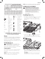
Minimum Gauge for Cord Sets
Volts
Total Length of Cord in Feet
(meters)
120 V 25 (7.6) 50 (15.2) 100 (30.5) 150 (45.7)
240 V 50 (15.2) 100 (30.5) 200 (61.0) 300 (91.4)
Ampere Rating
American Wire Gauge
More
Than
Not
More
Than
0 6 18 16 16 14
6 10 18 16 14 12
10 12 16 16 14 12
12 16 14 12 Not Recommended
The label on your tool may include the following symbols. The
symbols and their definitions are asfollows:
V ......................... volts
Hz .......................hertz
min ..................... minutes
or DC ......direct current
...................... Class I Construction
(grounded)
…/min ..............per minute
BPM .................... beats per minute
IPM ..................... impacts per minute
RPM .................... revolutions per
minute
sfpm ................... surface feet per
minute
SPM .................... strokes per minute
A ......................... amperes
W ........................watts
or AC ...........alternating current
or AC/DC .... alternating or
direct current
...................... Class II
Construction
(double insulated)
n
o
.......................no load speed
n .........................rated speed
......................earthing terminal
.....................safety alert symbol
.....................visible radiation
..................... wear respiratory
protection
..................... wear eye
protection
..................... wear hearing
protection
..................... read all
documentation
SAVE THESE INSTRUCTIONS FOR
FUTURE USE
Motor
Be sure your power supply agrees with the nameplate
marking. Voltage decrease of more than 10% will cause loss
of power and overheating. PORTER-CABLE tools are factory
tested; if this tool does not operate, check powersupply.
COMPONENTS (FIG. A)
WARNING: Never modify the power tool or any part
of it. Damage or personal injury couldresult.
Refer to Figure A at the beginning of this manual for a
complete list ofcomponents.
INTENDED USE
This wet tile saw is designed for cutting a variety of tile and
other tile typeapplications.
DO NOT cut wood, metals orplastics.
DO NOT use under wet conditions or in presence of
flammable liquids orgases.
DO NOT let children come into contact with the tool.
Supervision is required when inexperienced operators use
thistool.
ASSEMBLY AND ADJUSTMENTS
WARNING: To reduce the risk of serious personal
injury, turn unit off and disconnect it from
power source before making any adjustments or
removing/installing attachments or accessories.
An accidental start-up can causeinjury. Make sure the
switch is in the OFFposition.
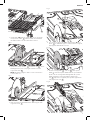
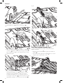
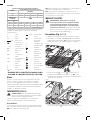
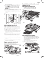
Assembly (Fig. A, C–I)
1. Place the tool on a stablesurface.
2. Unlock cutting cart
2
by pulling out on the cutting cart
lock pin
3
and slide the cutting cart back to reveal the
bladehousing.

ENGLISH
5
Fig. C
2
3. Install blade
13
onto the arbor
14
. Ensure the blade
is fully on the arbor
14
and fitted with the rotational
direction matches the direction of thewasher.
Fig. D
13
14
15
16
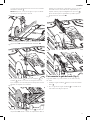
4. Install outer clamp washer
15
and blade nut
16
. While
holding blade in place, fully tighten blade nut with
supplied wrench
4
.
NOTE: Do not overtighten. Make sure the tile blade is
secure beforeuse.
15
Fig. E
16
5. Loosely install splash hood bracket
17
using the two
supplied screws
18
.
Fig. F
18
17
6. Use supplied edge guide
7
to align bracket
17
and
blade
13
as shown in Figure G. Once bracket is aligned,
fully tighten hood bracketscrews.
Fig. G
13
7
17
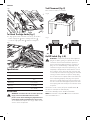
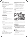
7. Remove carriage bolt
19
and nut
20
from splash
hood
5
and install splash hood onto the splash hood
bracket. Insert carriage bolt through both the splash
hood and bracket. Install and loosely tighten the
nut
20
. Adjust the height for your specific application.
Fully tighten the nut
20
.
Fig. H
20
19
5
17

ENGLISH
6
Fig. I
20
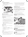
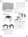
To Attach The Edge Guide (Fig. J)
The edge guide can be installed 1 of 2 ways, 45° or 90°.
1. Place edge gude
7
on the cutting cart fence
9
..
2. Turn the edge guide lock
8
clockwise totighten.
Fig. J
9
7
8
Specifcations
Voltage 120 V
Amps 6.5A
RPM 3600
Depth of Cut 1.25" (32 mm)
Blade Sizes 7" (178 mm)
Arbor Size 5/8" (16 mm)
OPERATION
WARNING: To reduce the risk of serious personal
injury, turn unit off and disconnect it from
power source before making any adjustments or
removing/installing attachments or accessories.
An accidental start-up can causeinjury. Make sure the
switch is in the OFFposition.
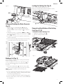
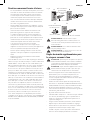
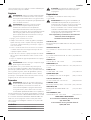
Tool Placement (Fig. K)
Place saw on a stable, levelsurface.
Fig. K
Fig. L
On/Off Switch (Fig. L, M)
WARNING: To avoid the possibility of the appliance
plug or receptacle getting wet, position the wet tile
saw to one side of a wall mounted receptacle to
prevent water from dipping onto the receptacle or
plug. The user should arrange a “drip loop” in the
cord connecting the saw to a receptacle (Fig. L). The
“drip loop” is that part of the cord below the level of
the receptacle, or the connector if an extension cord
is used, to prevent water traveling along the cord and
coming in contact with thereceptacle. Always plug
the saw into a GFCI receptacle and test to confirm the
GFCI is operatingproperly. If the plug or receptacle
does get wet, DON'T unplug the cord. Disconnect the
fuse or circuit breaker that supplies power to the tool.
Then unplug and examine for presence of water in the
receptacle.
To turn the wet tile saw on, lift up the on/off switch
1
.
The wet tile saw locks onautomatically.
To turn the tool off, push the on/off switchdown.
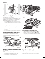
NOTE: A removable safety lock
26
. can be removed to
deter unauthorizeduse.

ENGLISH
7
Fig. M
26
1
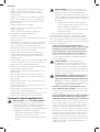
Filling and Draining the Water Reservoir
(Fig. N)
1. Plug the water reservoir drain hole
21
with the
drain plug
22
. Secure the drain plug into position
by tightening the attached wing nut
23
as shown in
FigureN.
2. Slowly fill the water reservoir to the MIN fill line
24
, to
prevent accidental overfilling. Do not fill above the MAX
fill line
25
. (Fig. N)
3. To drain the reservoir, p
lace a 5 gallon (19 liter) bucket
under the drainplug.
4. Remove the drain plug by loosening the attached wing
nut and allow the water to empty into thebucket.
22
23
21
Fig. N
25
24
Making a Cut (Fig. A)
Verify the proper alignment of the cutting cart and blade
before turning the saw on.
Secure tile against the cart fence, or edge guide
7
with
the edge guide lock
8
. Always keep hands away from
theblade.
1. Pull up the on/off switch
1
to turn the saw on. Wait
until the stream of water completely covers theblade.
NOTE: Cutting tile without water will damage the
cuttingwheel.
2. Ease the cutting cart toward the blade then slowly feed
the tile into the blade. Continue pushing until the blade
cuts completely through thetile.
3. Turn the saw off by pushing the on/off switch
1
down.
4. After the blade stops, remove the tile and remnant from
the cuttingcart.
Locking the Cutting Cart (Fig. O)
There is one locking position for thecart.
Move the cart to the lock position and lock the cart by
pushing the pin
3
into a hole in therail.
Fig. O
3
Removal and Installation of the Cutting
Cart (Fig. A, P, Q)
To Remove the Cutting Cart
1. Unlock the cutting cart stop
10
.
2. Slide the cutting cart off thetool.
Fig. P
Fig. Q

ENGLISH
8
To Install the Cutting Cart
1. Align rail guide rollers
28
on the cutting cart to the
rails
29
on the tool. Make sure the cutting cart lock pin
is in the unlockposition.
2. Slide the cutting cart onto thetool.
3. Lock the cutting cartstop.
Fig. R
28
29
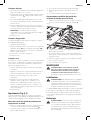
Types of Cuts (Fig. A, S)
Always do a practice run to acquaint yourself with the path
of the blade. Practice on a scrap tile to ensure that you are
comfortable with the feel of the cutting operation. Push the
cart past the blade before turning the sawon.
Straight Cuts
1. Using a marker or grease pencil, mark the area to be cut
ontile.
2. Place the tile on the cutting cart against the cutting cart
fence
9
and align your mark with theblade.
3. Pull the on/off switch up to turn the saw on and wait for
the blade to be completely covered withwater.
4. Ease the cutting cart toward the blade then slowly feed
the tile into the blade. Continue pushing until the blade
cuts completely through thetile.
NOTE: The flip hood on the splash hood can be rotated
up to help align the line on the tile with the blade.
5. Turn off thesaw.
Diagonal Cuts
Diagonal cuts are also referred to as “long point to long
point cuts.”
1. Install the edgeguide.
2. Align the point of the tile closest to the cutting cart
fence
9
with the cut indicator
30
.
3. Align the front of the tile to the blade and hold against
the edgeguide.
4. Turn the saw on and make thecut.
5. Turn off thesaw.
L-Cuts
An L-cut is a section that is removed from of a piece of tile
and is used when cutting a piece of tile to fit in a corner of a
cabinet or piece of trimmolding.
1. Outline the area to be cut on both sides of thetile.
2. Align the tile to the cutting cart fence and make the cut
far enough into the tile withoutovercutting.
3. Make a cut on the other mark on the tile withoutovercutting.
4. Turn the tile over and make the cut along one of the
outlines, but this time an overcut can occur without
damaging the exposed surface of the tile due to the
radius of the blade. Overcut the other line and the cut
piece should be separate from the rest of thetile.
5. Turn off thesaw.
Adjustments (Fig. A, S)
The cutting cart fence and rails are properly aligned from
the factory. Shipping or prolonged use can cause them to
become misaligned and needadjustment.
Squaring the Cutting Cart Fence to the Blade
1. Lay a 90º square flat on the blade surface with one end
against the cart fence
9
.
2. If the blade is not 90º to the cart fence, the rail will
needadjustment.
3. Loosen the cart fence adjustmentscrew.
4. Adjust the fence until it is square to theblade.
5. Tighten the cart fence adjustmentscrew.
Adjusting the Cutting Cart Parallel to
the Blade
1. Lay a 90º square flat on the blade surface with one end
against the cart fence
9
.
FIg. S
30
2. If the blade is not 90º to the cart fence, the rail will
needadjustment.
3. Loosen the three front and rear screws on the left guide
rail, and adjust rail until it is parallel to the blade..
4. Move the rail until the cart fence is square to theblade.
5. Tighten the three railscrews.
MAINTENANCE
WARNING: To reduce the risk of serious personal
injury, turn unit off and disconnect it from
power source before making any adjustments or
removing/installing attachments or accessories.
An accidental start-up can causeinjury.
Lubrication
WARNING: NEVER spray or in any other way apply
lubricants or cleaning solvents inside the tool. This can
seriously affect the life and performance of the tool
and may result in personalinjury.

ENGLISH
9
PORTER-CABLE tools are properly lubricated at the factory
and are ready for use. However, it is recommended that,
once a year, you take or send the tool to a certified service
center for a thorough cleaning andinspection.
Cleaning
WARNING: Blow dirt and dust out of all air vents with
clean, dry air at least once a week. To minimize the risk
of eye injury, always wear ANSI Z87.1 approved eye
protection when performingthis.
WARNING: Never use solvents or other harsh
chemicals for cleaning the non-metallic parts of
the tool. These chemicals may weaken the plastic
materials used in these parts. Use a cloth dampened
only with water and mild soap. Never let any liquid
get inside the tool; never immerse any part of the tool
into aliquid.
1. Turn off and remove battery from thesaw.
2. P
lace a 5 gallon (19 liter) bucket under the drain plug.
Remove the drain plug by loosening the attached wing
nut and allow the water to empty into thebucket.
3. Slide the cutting cart off the rail system. Spray the cutting
cart with a hose or wipe with a grout sponge orrag.
4. Wipe the rails with a grout sponge or a rag. Spray
lubricants are not required on the guide rail orwheels.
5. Clean the water reservoir by wiping with a groutsponge.
WARNING: Do not spray with water. Some water
may reach the motorarea.
Use only mild soap and a damp cloth to clean the tool.
Many household cleaners contain chemicals which
could seriously damage plastic. Also, do not use gasoline,
turpentine, lacquer or paint thinner, dry cleaning fluids or
similar products. Try not to let any liquid get inside the tool;
never immerse any part of the tool into aliquid.
Accessories
WARNING: Since accessories, other than those
offered by PORTER-CABLE, have not been tested with
this product, use of such accessories with this tool
could be hazardous. To reduce the risk of injury, only
PORTER-CABLE recommended accessories should be
used with thisproduct.
A complete line of accessories is available from your
PORTER-CABLE Factory Service Center or a PORTER-CABLE
Authorized Warranty Service Center. Please visit our Web
Site www.portercable.com for a catalog or for the name of
your nearestsupplier.
Blades
7" (178 mm) Ceramic wheel
7" (178 mm) Porcelain wheel
CAUTION: The use of any other accessory
not recommended for use with this tool could
behazardous.
Repairs
WARNING: To assure product SAFETY and
RELIABILITY, repairs, maintenance and adjustment
(including brush inspection and replacement, when
applicable) should be performed by a PORTER-CABLE
factory service center or a PORTER-CABLE authorized
service center. Always use identical replacementparts.
Register Online
Thank you for your purchase. Register your product nowfor:
• WARRANTY SERVICE: Registering your product will
help you obtain more efficient warranty service in case
there is a problem with yourproduct.
• CONFIRMATION OF OWNERSHIP: In case of
an insurance loss, such as fire, flood or theft, your
registration of ownership will serve as your proof
ofpurchase.
• FOR YOUR SAFETY: Registering your product will
allow us to contact you in the unlikely event a safety
notification is required under the Federal Consumer
SafetyAct.
Register online at www.portercable.com/register.
THREE YEAR LIMITED WARRANTY
PORTER-CABLE will repair or replace, without charge, any
defects due to faulty materials or workmanship for three
years from the date of purchase for tools (two years for
batteries). This warranty does not cover part failure due to
normal wear or tool abuse. For further detail of warranty
coverage and warranty repair information, visit www.
portercable.com or call (888) 848-5175. This warranty does
not apply to accessories or damage caused where repairs
have been made or attempted by others. This warranty
gives you specific legal rights and you may have other rights
which vary in certain states orprovinces.
In addition to the warranty, PORTER-CABLE tools are
covered by our:
1 YEAR FREE SERVICE: PORTER-CABLE will maintain the tool
and replace worn parts caused by normal use, for free, any
time during the first year afterpurchase.
90 DAY MONEY BACK GUARANTEE: If you are not completely
satisfied with the performance of your PORTER-CABLE
Power Tool for any reason, you can return it within 90 days
from the date of purchase with a receipt for a full refund –
no questionsasked.
LATIN AMERICA: This warranty does not apply to products
sold in Latin America. For products sold in Latin America,
see country specific warranty information contained in
the packaging, call the local company or see website for
warrantyinformation.
To register your tool for warranty service visit our website at
www.portercable.com.

ENGLISH
10
WARNING LABEL REPLACEMENT
If your warning labels become illegible or are missing, call
(888) 848-5175 for a freereplacement.
4825 Highway 45 North
Jackson, Tennessee 38305
(888) 848-5175
www.portercable.com
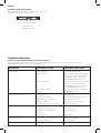
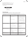
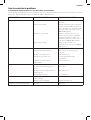
Troubleshooting Guide
BE SURE TO FOLLOW SAFETY RULES AND INSTRUCTIONS
For assistance with your product, visit our website at www.portercable.com for a list of service centers, or call the
PORTER-CABLE Customer Care Center at (888) 848-5175.
PROBLEM POSSIBLE CAUSE POSSIBLE SOLUTION
Unit will not start. Cord is not plugged in.
Circuit fuse is blown.
Circuit breaker is tripped.
Cord or switch is damaged.
Plug tool into a working outlet.
Replace circuit fuse. (If the product repeatedly
causes the circuit fuse to blow, discontinue
use immediately and have it serviced by an
authorized PORTER-CABLE service center.
Reset circuit breaker. (If the product repeatedly
causes the circuit breaker trip, discontinue
use immediately and have it serviced by an
authorized PORTER-CABLE service center.
Have cord or switch replaced at an authorized
PORTER-CABLE service center.
Saw makes unsatisfactory cuts. Dull cutting wheel.
Not enough water in the tub.
Cutting wheel mounted backwards.
Build up on cutting wheel
Incorrect cutting wheel for work being done.
Replace cutting wheel.
Check water level and add water if necessary.
Turn cutting wheel around.
Use dressing stone to remove build up.
Change the cutting wheel.
Unit does not make accurate cuts. Edge guide not secure to fence.
Cutting wheel is not square to fence.
Cutting wheel is not perpendicular to
cart surface.
Workpiece moving.
Check and adjust.
Check and adjust.
Check and adjust fence.
Use edge guide.
Unit vibrates excessively. Saw not mounted on a level surface.
Damaged saw cutting wheel.
Reposition on a level surface.
Replace cutting wheel.
Cutting wheel does not come up to speed. Arbor loose. Tighten arbor.

FRANÇAIS
11
Définitions : symboles et termes d'alarmes sécurité
Ces guides d'utilisation utilisent les symboles et termes d'alarmes sécurité suivants pour vous prévenir de situations
dangereuses et de risques de dommages corporels ou matériels.
DANGER: indique une situation dangereuse imminente qui, si elle n’est pas évitée, entraînera la mort ou des
blessuresgraves.
AVERTISSEMENT: indique une situation potentiellement dangereuse qui, si elle n’est pas évitée, pourrait entraîner la
mort ou des blessuresgraves.
ATTENTION: indique une situation potentiellement dangereuse qui, si elle n’est pas évitée, pourrait entraîner des
blessures légères oumodérées.
(Si utilisé sans aucun terme) Indique un message propre à la sécurité.
AVIS : indique une pratique ne posant aucun risque de dommages corporels mais qui par contre, si rien n’est fait
pour l’éviter, pourrait poser des risques de dommages matériels.
AVERTISSEMENT! lire tous les avertissements de
sécurité et toutes les directives. Le non-respect
des avertissements et des directives pourrait se
solder par un choc électrique, un incendie et/ou une
blessuregrave.
AVERTISSEMENT : afin de réduire le risque de
blessures, lire le mode d’emploi del’outil.
Pour toute question ou commentaire à propos de
n'importe quel outil PORTER-CABLE, appelez-nous au
numéro sans frais: 888-848-5175.
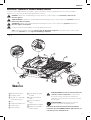
1
Bouton Marche/Arrêt
2
Chariot de coupe
3
Goupille de verrouillage
du chariot de coupe
4
Clé
5
Capot antiéclaboussures
6
Capot à rabat
7
Guide de bord
8
Verrouillage du guide
de bord
9
Guide du chariot de
coupe
10
Arrêt du chariot de
coupe
11
Cordon d’alimentation
12
Enrouleur de cordon
d’alimentation
Français (traduction de la notice d’instructions originale)
Fig. A
1
11
2
6
12
7
3
8
9
10
5
4

FRANÇAIS
12
AVERTISSEMENTS DE SÉCURITÉ GÉNÉRAUX
POUR LES OUTILS ÉLECTRIQUES
AVERTISSEMENT! lire tous les avertissements de
sécurité et toutes les directives. Le non-respect
des avertissements et des directives pourrait se
solder par un choc électrique, un incendie et/ou une
blessuregrave.
CONSERVER TOUS LES
AVERTISSEMENTS ET TOUTES
LES DIRECTIVES POUR UN USAGE
ULTÉRIEUR
AVERTISSEMENT : Ne jamais utiliser la scie avec de
l’eau salée ou un fluide conducteur.
AVERTISSEMENT : Lorsqu’on utilise un outil
électrique, on doit suivre les consignes de sécurité
élémentaires, y compris les directives indiquées aux
présentes, afin d’éviter les risques d’incendie, de choc
électrique et de blessure.
• GARDER LES DISPOSITIFS DE PROTECTION EN PLACE
et en bon état de fonctionnement.
• RETIRER LES CLÉS DE RÉGLAGE ; prendre l’habitude
de s’assurer que les clés de réglage sont retirées de l’outil
avant de ledémarrer.
• GARDER L’AIRE DE TRAVAIL PROPRE ; les espaces
de travail et les établis encombrés sont propices aux
blessures.
• UTILISER L’OUTIL DANS DES ENDROITS APPROPRIÉS;
ne pas exposer l’outil à la pluie ou à la neige, ni l’utiliser
dans des endroits humides ou mouillés. Garder l’aire de
travail bien éclairée.
• TENIR LES ENFANTS À L’ÉCART ; s’assurer que personne
ne s’approche de l’aire de travail.
• S’ASSURER QUE L’ATELIER EST SÛR POUR LES
ENFANTS; utiliser des cadenas, des interrupteurs centraux
ou enlever les commandes de démarrage.
• NE PAS FORCER L’OUTIL ; pour obtenir de meilleurs
résultats et prévenir les risques de blessure, laisser l’outil
couper à la vitesse pour laquelle il a été conçu.
• UTILISER L’OUTIL APPROPRIÉ ; ne pas forcer l’outil ou
l’accessoire, ni l’utiliser pour des travaux autres que ceux
pour lesquels il a été conçu.
• UTILISER LES RALLONGES APPROPRIÉES ; s’assurer
que la rallonge électrique est en bon état et qu’elle est
en mesure de porter le courant nécessaire à l’outil. Une
rallonge de calibre inférieur entraînera une chute de
tension se traduisant par une perte de puissance et une
surchauffe. Le tableau ci-dessous illustre les calibres
que l’on doit utiliser selon la longueur de la rallonge et
l’intensité nominale indiquée sur la plaque signalétique.
En cas de doute, utiliser le calibre suivant. Plus le calibre est
petit, plus la rallonge peut porter de courant.
• PORTER DES VÊTEMENTS APPROPRIÉS ; ne pas porter
de vêtements amples ni de gants, de cravate, de bague,
de bracelet ou d’autres bijoux, car ceux-ci peuvent rester
coincés dans les pièces mobiles. On recommande le port
de chaussures antidérapantes. Couvrir ou attacher les
cheveux longs. Se tenir éloigné des évents puisque ces
derniers pourraient camoufler des pièces mobiles.
• TOUJOURS PORTER DES LUNETTES DE SÉCURITÉ
; porter aussi un masque facial ou un masque anti-
poussières lorsqu’on soulève de la poussière. Les lunettes
ordinaires protègent uniquement les yeux contre les chocs
et ne sont PAS des lunettes de protection.
• IMMOBILISER LA PIÈCE ; toujours placer la tuile à plat
sur l’établi et la fixer solidement contre le guide.
• Ne jamais utiliser un chauffe-cuvette ou tout autre
dispositif de chauffage pour chauffer l’eau afin d’éviter
d’endommager l’outil ou d’entraîner des risques d’incendie
ou de blessure.
• NE PAS TROP ÉTENDRE LES BRAS ; les pieds doivent
rester ancrés fermement au sol afin de maintenir son
équilibre en tout temps.
• BIEN ENTRETENIR L’OUTIL ; afin d’obtenir de meilleurs
résultats et faire preuve de prudence, garder l’outil propre
et bien aiguisé. Suivre les consignes lorsqu’on lubrifie ou
qu’on remplace les accessoires.
• DÉBRANCHER L’OUTIL avant de procéder à l’entretien
ou de remplacer des accessoires comme les lames, les
brides de serrage, les rallonges, etc.
• RÉDUIRE LES RISQUES DE DÉMARRAGE ACCIDENTEL ;
s’assurer que l’interrupteur est en position d’arrêt avant de
brancher l’outil.
• UTILISER LES ACCESSOIRES RECOMMANDÉS ;
consulter le manuel d’utilisation pour savoir quels
accessoires sont appropriés. L’utilisation d’accessoires
autres que ceux recommandés pourrait entraîner
desblessures.
• NE JAMAIS SE METTRE DEBOUT SUR L’OUTIL;
si l’outil se renverse ou si l’organe de coupe est
touché accidentellement, cela pourrait entraîner des
blessuresgraves.
• VÉRIFIER LES PIÈCES ENDOMMAGÉES ; avant de
poursuivre les travaux, on doit examiner attentivement
les dispositifs de protection, ou toute autre pièce
endommagée, afin de s’assurer qu’il fonctionne toujours
adéquatement et qu’il est en mesure d’effectuer les
travaux pour lesquels il a été conçu. Vérifier les pièces
mobiles afin de s’assurer qu’elles sont bien alignées et
qu’elles ne restent pas coincées; vérifier également les
pièces et les assemblages afin de s’assurer qu’il n’y a
aucun bris ni aucune autre condition susceptible de nuire
au bon fonctionnement de l’outil. On doit faire réparer
ou remplacer toute pièce endommagée, y compris les
dispositifs de protection.
• TOUJOURS RESPECTER LE SENS D’AVANCE en
faisant avancer la pièce dans la lame dans le sens de
rotationseulement.
• NE JAMAIS LAISSER L’OUTIL FONCTIONNER SANS
SURVEILLANCE; COUPER L’ALIMENTATION et attendre
que l’outil s’arrête complètement avant de quitter les lieux.
• PIÈCES DE RECHANGE : Lors de l’entretien, n’utiliser que
des pièces de rechange identiques.

FRANÇAIS
13
Directives concernant la mise à la terre
• En cas de défaillance technique ou de panne, la mise à la
terre offre un chemin de moindre résistance au courant
électrique pour réduire tout risque de choc électrique.
Cet outil est pourvu d’un cordon électrique muni d’un
conducteur de protection et d’une fiche de mise à la
terre. Cette fiche doit être branchée dans prise adéquate
installée correctement et mise à la terre conformément
aux codes et régulationslocales.
• Ne pas modifier la fiche fournie avec l’appareil. Si elle ne
rentre pas dans la prise, faire installer une prise adéquate
par un électricienqualifié.
• Tout branchement non conforme du conducteur de
protection augmente les risques de choc électrique.
Le conducteur dont la surface externe d’isolation est
verte avec ou sans rayures jaunes est le conducteur de
protection. En cas de réparation ou de remplacement du
cordon électrique ou de la fiche, Ne jamais connecter le
conducteur de protection à une borne soustension.
• Si les Directives de mise à la terre ne sont pas
complètement comprises ou si on n’est pas sûr que
l’appareil est correctement mis à la terre, faire appel à un
électricien qualifié ou à du personnel d’entretien.
• N’utiliser que des rallonges trifilaires munies de fiches
tripolaires et des prises tripolaires acceptant la fiche de
l’outil.
• Réparer ou remplacer immédiatement tout cordon
endommagé ouusé.
Cet outil doit être mis à la terre afin de protéger l’utilisateur
contre les risques de choc électrique. Cet outil est doté d’un
cordon trifilaire et d’une fiche de terre à trois broches; on
doit en raccorder la fiche dans une prise murale appropriée.
Le conducteur vert (ou vert et jaune) du cordon est le fil
de mise à la terre. Ne jamais raccorder le fil vert (ou vert et
jaune) à une borne sous tension. Les outils destinés à être
raccordés à un circuit d’alimentation électrique ayant une
tension nominale de moins de 150 volts sont en effet munis
d’une fiche qui est semblable à celle illustrée à la SchémaA,
alors que ceux destinés à être raccordés à un circuit dont la
tension nominale varie entre 150 et 250 volts sont munis
d’une fiche qui ressemble à celle illustrée à la Schéma D.
On peut utiliser un adaptateur, comme celui illustré aux
Schéma B et C, pour brancher la fiche de l’outil (Schéma A)
à une prise à deux broches. On doit mettre cet adaptateur à
la terre en en reliant l’oeillet, la cosse ou tout autre dispositif
de couleur verte à un élément mis à la terre de manière
permanente, comme une boîte à prises bien mise à la
terre. Aucun adaptateur n’est disponible pour une fiche
semblable à celle illustrée à la SchémaD. IL EST CEPENDANT
INTERDIT DE SE SERVIR D’UN TEL ADAPTATEUR (SCHÉMA B
ET C) AUCANADA.
Fig. B
A B
BROCHE DE MISE À LA TERRE
BOÎTE DE PRISES
DE COURANT
MISES À LA
TERRE
C
D
ADAPTATEUR POUR
DISPOSITIFS DE
BROCHE DE MISE À LA TERRE
MISE À LA TERRE
AVERTISSEMENT: afin de réduire le risque
d’électrocution, gardez tous les branchements secs
et au-dessus du sol. Ne pas toucher la fiche avec les
mainsmouillées.
AVERTISSEMENT: la scie doit être branchée dans
une prise protégée DDFT.
AVERTISSEMENT: ne jamais utiliser la scie avec de
l’eau salée ou un fluide conducteur.
Règles de sécurité supplémentaires pour
la scie pour carreaux à l’eau
ATTENTION: portez toujours des protecteurs pour les
oreilles durant l’utilisation. Dans certaines conditions
et selon la durée d’utilisation, le bruit provenant de ce
produit peut contribuer à la perte de l’audition.
ATTENTION: ne pas brancher l’appareil à une source
d’alimentation électrique jusqu’à ce que vous ayez
entièrement lu et compris toutes lesinstructions.
• Utilisez un équipement de sécurité. Portez toujours une
protection des yeux. Les masques antipoussières, les
chaussures de sécurité antidérapantes, le casque de
sécurité et la protection auditive doivent être utilisés pour
les conditionsappropriées.
• Gardez vos mains hors de portée de la trajectoire de la
lame de la scie. NE JAMAIS COUPER UN MORCEAU OÙ LES
MAINS SERAIENT À 76 mm (3 PO) OU MOINS DELALAME.
• Ne effectuer toute opération à main levée, c’est-à-dire
sans tenir fermement la pièce de travail contre le guide du
chariot ou le guidedebord.
• Ne jamais toucher l’arrière de lalame.
• À NE PAS FAIRE - Couper à sec. Si la lame n’est pas refroidie
avec de l'eau, des dommages graves se produiront. La
coupe à sec augmentera l’exposition à la poussière en
suspensiondangereuse.
• Éteignez l’outil et attendez que la lame s’arrête avant de
déplacer la pièce de travail ou de modifier lesréglages.
• Afin de réduire le risque de blessure, retournez le chariot
complètement à l’arrière après chaquecoupe.
• À FAIRE - Toujours s’assurer que la lame tourne dans le
bon sens comme indiqué par la flèche sur lalame.

FRANÇAIS
14
• À FAIRE - Toujours utiliser le capotantiéclaboussures.
• À FAIRE - S’assurer que toutes les poignées à pince
et tous les boulons sont serrés avant de commencer
touteopération.
• À FAIRE - S’assurer que toutes les rondelles de la pince
et de la lame sont propres et que les côtés enfoncés du
collier soient contre la lame. Serrez l’écrou de l’axe de
façonsécuritaire.
• À FAIRE - Garder la lame bienalignée.
• À FAIRE - Garder les prises d’air du moteur libres de
particules et desaleté.
• À FAIRE - Toujours vider l’eau du réservoir avant
de transporter. L’eau peut éclabousser les
composantesélectriques.
• À FAIRE - Garder les mains hors de portée de la trajectoire
de la lame de lascie.
• À NE PAS FAIRE - Tenter d’utiliser une autre tension que
celle indiquée. Une mauvaise tension peut entraîner un
choc, un incendie ou une utilisationimprévisible.
• À NE PAS FAIRE - Utiliser des lames plus grandes ou plus
petites que celles qui sontrecommandées.
• À NE PAS FAIRE - Forcer l’action de la coupe. Laissez
le moteur atteindre sa pleine vitesse avant de couper.
Le blocage ou le blocage partiel peut entraîner des
dommagesgraves.
• À NE PAS FAIRE - Utiliser des meules abrasives pour couper
le métal. La chaleur excessive et les particules abrasives
générées par celles-ci endommageront lascie.
• À FAIRE - Utiliser seulement des meules à jante continue,
aucun bord dentelé ou lamedentée.
• À NE PAS FAIRE - Permettre à tout le monde de se tenir
derrière lascie.
• À NE PAS FAIRE - Placer une main ou l’autre dans la
zone de la lame lorsque la scie est branchée à la source
d’alimentation.
• À NE PAS FAIRE - Utiliser les lames ayant une puissance
inférieure à 5000tr/min.
• À NE PAS FAIRE - Placer les mains plus près que 76mm
(3po) de la lame de lascie.
• À NE PAS FAIRE - Toucher l’arrière ou le dessous de la scie à
moins qu’elle soit éteinte oudébranchée.
• À NE PAS FAIRE - Bouger une main ou l’autre de la scie ou
de la pièce de travail jusqu’à ce que la lame s’arrête.
Consigne de sécurité supplémentaire
AVERTISSEMENT: porter SYSTEMATIQUEMENT
des lunettes de protection. Les lunettes courantes
NE sont PAS des lunettes de protection. Utiliser aussi
un masque antipoussières si la découpe doit en
produire beaucoup. PORTER SYSTÉMATIQUEMENT UN
ÉQUIPEMENT DE SÉCURITÉ HOMOLOGUÉ:
• Protection oculaire ANSI Z87.1 (CAN/CSA Z94.3);
• Protection auditive ANSI S12.6 (S3.19);
• Protection des voies respiratoires NIOSH/OSHA/
MSHA.
AVERTISSEMENT: les scies, meules, ponceuses,
perceuses ou autres outils de construction peuvent
produire des poussières contenant des produits
chimiques reconnus par l’État californien pour causer
cancers, malformations congénitales ou être nocifs au
système reproducteur. Parmi ces produits chimiques,
on retrouve:
• Le plomb dans les peintures à base de plomb;
• La silice cristallisée dans les briques et le ciment,
ou autres produits de maçonnerie; et
• L’arsenic et le chrome dans le bois ayant subi un
traitementchimique.
Le risque associé à de telles expositions varie selon la
fréquence à laquelle on effectue ces travaux. Pour réduire
toute exposition à ces produits: travailler dans un endroit
bien aéré, en utilisant du matériel de sécurité homologué, tel
un masque antipoussières spécialement conçu pour filtrer les
particulesmicroscopiques.
• Limiter toute exposition prolongée avec les
poussières provenant du ponçage, sciage, meulage,
perçage ou toute autre activité de construction.
Porter des vêtements de protection et nettoyer à
l’eau savonneuse les parties du corps exposées. Le
fait de laisser la poussière pénétrer dans la bouche, les
yeux ou la peau peut favoriser l’absorption de produits
chimiquesdangereux.
AVERTISSEMENT: cet outil peut produire et/
ou répandre de la poussière susceptible de causer
des dommages sérieux et permanents au système
respiratoire. Utiliser systématiquement un appareil
de protection des voies respiratoires homologué par
le NIOSH ou l’OSHA. Diriger les particules dans le sens
opposé au visage et aucorps.
AVERTISSEMENT: pendant l’utilisation, porter
systématiquement une protection auditive
individuelle adéquate homologuée ANSI S12.6
(S3.19). Sous certaines conditions et suivant la durée
d’utilisation, le bruit émanant de ce produit pourrait
contribuer à une perte de l’acuitéauditive.
• Prendre des précautions à proximité des évents,
car ils cachent des pièces mobiles. Vêtements amples,
bijoux ou cheveux longs risquent de rester coincés dans
ces piècesmobiles.
• Pour la sécurité de l’utilisateur, utiliser une rallonge
de calibre adéquat (AWG, American Wire Gauge
[calibrage américain normalisé des fils électriques]).
Plus le calibre est petit, et plus sa capacité est grande. Un
calibre16, par exemple, a une capacité supérieure à un
calibre18. L’usage d’une rallonge de calibre insuffisant
causera une chute de tension qui entraînera perte de
puissance et surchauffe. Si plus d’une rallonge est utilisée
pour obtenir une certaine longueur, s’assurer que chaque
rallonge présente au moins le calibre de fil minimum. Le
tableau ci-dessous illustre les calibres à utiliser selon la
longueur de rallonge et l’intensité nominale indiquée sur
la plaque signalétique. En cas de doute, utiliser le calibre
suivant. Plus le calibre est petit, plus la rallonge peut
supporter decourant.

FRANÇAIS
15
Calibre minimum pour les cordons d'alimentation
Volts
Longueur totale du cordon
d'alimentation en mètre (pieds)
120 V 7,6 (25) 15,2 (50) 30,5 (100) 45,7 (150)
240 V 15,2 (50) 30,5 (100) 61,0 (200) 91,4 (300)
Ampères
AWG
Plus que Pas plus
que
0 6 18 16 16 14
6 10 18 16 14 12
10 12 16 16 14 12
12 16 14 12 Non recommandé
L’étiquette apposée sur votre outil peut inclure les symboles
suivants. Les symboles et leur définition sont indiqués ci-après:
V ......................... volts
Hz ....................... hertz
min ..................... minutes
or DC ...... courant continu
...................... fabrication classe I
(mis à la terre)
…/min .............. par minute
BPM .................... battements par
minute
IPM ..................... impacts par minute
RPM .................... revolutions per
minute
sfpm ................... pieds linéaires par
minute (plpm)
SPM (FPM) ......... fréquence par
minute
A ......................... ampères
W ........................ watts
or AC ........... courant alternatif
or AC/DC .... courant alternatif
ou continu
...................... fabrication classe II
(double isolation)
n
o
....................... vitesse à vide
n ......................... vitesse nominale
...................... borne de terre
...................... symbole
d’avertissement
..................... radiation visible
..................... protection
respiratoire
.....................protection oculaire
.....................protection auditive
..................... lire toute la
documentation
CONSERVER CES CONSIGNES POUR
UTILISATION ULTÉRIEURE
Moteur
S’assurer que le bloc d’alimentation est compatible avec
l’inscription de la plaque signalétique.Une diminution
de tension de plus de 10 % provoquera une perte de
puissance et une surchauffe. Les outils PORTER-CABLE
sont testés en usine; si cet outil ne fonctionne pas, vérifier
l’alimentationélectrique.
DESCRIPTION (FIG. A)
AVERTISSEMENT: ne jamais modifier l’outil
électrique ni aucun de ses composants, car il y a
risques de dommages corporels oumatériels.
Reportez-vous en FigureA au début de ce manuel pour
obtenir la liste complète descomposants.
USAGE PRÉVU
Cette scie pour carreaux à l’eau est conçue pour couper
divers carreaux et pour d’autres applications de type
decarreaux.
NE PAS couper le bois, les métaux ou lesplastiques.
NE PAS les utiliser en milieu ambiant humide ou en
présence de liquides ou de gazinflammables.
NE PAS le laisser à la portée des enfants. Une supervision
est nécessaire auprès de tout utilisateur nonexpérimenté.
ASSEMBLAGE ET AJUSTEMENTS
AVERTISSEMENT: afin de réduire le risque
de blessure corporelle, éteignez l’appareil et
débranchez-le de la source d’alimentation
avant d’effectuer tout ajustement ou de retirer/
installer des pièces ou des accessoires. Un
démarrage accidentel peut causer des blessures.
Assurez-vous que le bouton Marche/Arrêt est en
positionARRÊT.
Assemblage (Fig. A, C–I)
1. Placez l’outil sur une surfacestable.
2. Déverrouillez le chariot de coupe
2
tirant sur la goupille
de verrouillage du chariot de coupe
3
et glissez le
chariot de coupe vers l’arrière pour montrer le boîtier
de lalame.
Fig. C
2
3. Installez la lame
13
sur l’axe
14
. Assurez-vous que la
lame est entièrement sur l’axe
14
et ajustée avec le
sens de la rotation qui correspond à celui de larondelle.
Fig. D
13
14
15
16
4. Installez la rondelle de la pince extérieure
15
et
l’écrou de la lame
16
. Tout en maintenant la lame en
place, serrez entièrement l’écrou de la lame avec la clé
fournie
4
.
REMARQUE: Ne pas trop serrer. Assurez-vous que la
lame pour carreaux est sécuritaire avant l’utilisation.

FRANÇAIS
16
15
Fig. E
16
5. Installez sans serrer le support du capot
antiéclaboussures
17
des deux vis fournies
18
.
Fig. F
18
17
6. Utilisez le guide de bord
7
pour aligner le support
17
et la lame
13
comme illustré dans la Figure G. Une fois
que le support est aligné, serrez entièrement les vis du
support ducapot.
Fig. G
13
7
17
7. Retirez le boulon de carrosserie
19
et l’écrou
20
du capot antiéclaboussures
5
et installez-le sur son
support. Insérez le boulon de carrosserie à travers
le capot antiéclaboussures et le support. Installez et
serrez légèrement l’écrou
20
. Ajustez la hauteur à votre
application spécifique. Serrez entièrement l’écrou
20
.
Fig. H
20
19
5
17
Fig. I
20
Pour fixer le guide de bord (Fig. J)
Le guide de bord peut être installé selon une des deux
façons, 45° ou 90°.
1. Placez le guide de bord
7
sur le guide du chariot de
coupe
9
.
2. Tournez le verrou du guide de bord
8
dans le sens des
aiguilles d’une montre pourserrer.
Fig. J
9
7
8

FRANÇAIS
17
Caractéristiques techniques
Tension 120 V
Ampères 6,5 A
tr/min 3600
Profondeur de coupe 32 mm (1,25 po.)
Diamètres de lames 178 mm (7 po.)
Diamètre de l’axe 16 mm (5/8 po.)
UTILISATION
AVERTISSEMENT: pour réduire le risque de
blessures graves, éteindre l’outil et retirer le
débrancher avant d’effectuer tout réglage
et d’enlever ou d’installer tout accessoire. Un
démarrage accidentel peut provoquer desblessures.
Assurez-vous que le bouton Marche/Arrêt est en
positionARRÊT.
Placement de l’outil (Fig. K)
Placez la scie sur une surface planestable.
Fig. K
Fig. L
Bouton Marche/Arrêt (Fig. L, M)
AVERTISSEMENT : pour éviter la possibiité que la
fiche ou la prise de l’appareil soient éclaboussés d’eau,
placer la scie coupe-tuile mouillée hors du plan de
la prise murale pour prévenir toute projection d’eau
sur le raccordement électrique. Le raccordement
du cordon devrait avoir une flèche ou boucle
intermédiaire permettant l’égouttement de toute
éclaboussure (Fig. L). La flèche ou boucle du cordon
devrait se trouver en-dessous du niveau de la prise
ou de la connexion d’éventuelle rallonge électrique
pour prévenir tout égouttement d’eau sur les contacts
électriques. Toujjours brancher la scie dans une prise
disjoncteur différentiel de fuite à la terre (DDFT) et
confirmer son déclenchement par son bouton d’essai.
En cas d’éclaboussure de la prise ou connextion, NE
PAS TOUCHER AU CORDON. Coupez l’alimentation
(disjoncteur ou fusible) au tableau d’alimentation du
circuit de l’outil. Seulement après avoir fait cela vous
pourrez vérifier la présence d'eau dans la prise de
connexion.
Pour mettre la scie pour carreaux à l’eau en marche, lever le
bouton Marche/Arrêt
1
.
La scie pour carreaux à l’eau se met automatiquement
enmarche.
Pour éteindre l’outil, poussez le bouton Marche/Arrêt vers
lebas.
REMARQUE: Un verrou de sécurité amovible
26
peut être
retiré pour empêcher une utilisation nonautorisée.
Fig. M
26
1
Replir et vider le réservoir d’eau (Fig. N)
1. Placez le bouchon de vidange
22
sur le trou du drain
du réservoir d’eau
21
. Sécurisez le bouchon de vidange
en place en serrant l’écrou à oreilles fixé
23
comme
illustré dans la FigureN.
2. Remplissez lentement le réservoir d’eau jusqu’à la
ligne de remplissage MIN
24
, afin de prévenir de trop
remplir accidentellement. Ne pas remplir au-dessus de
la ligne de remplissage MAX
25
. (Fig. N)
3. Pour vider le réservoir, placez un seau de 19litres
(5gallons) sur le bouchon devidange.
4. Retirez le bouchon de vidange en desserrant l’écrou à
oreilles fixé et laissez l’eau se vide dans leseau.

FRANÇAIS
18
22
23
21
Fig. N
25
24
Faire une coupe (Fig. A)
Vérifiez l’alignement approprié du chariot de coupe et de la
lame dans mettre la scie enmarche.
Sécurisez le carreau contre le guide du chariot ou le guide
de bord
7
avec le verrou du guide de bord
8
. Gardez
toujours vos mains hors de portée de lalame.
1. Levez le bouton Marche/Arrêt
1
pour mettre la scie
en marche. Attendez jusqu’à ce que le jet d’eau couvre
entièrement lalame.
REMARQUE: Couper le carreau sans eau peut
endommager lacoupe.
2. Dirigez le chariot de coupe vers la lame, puis poussez
le carreau dans la lame. Continuez à pousser jusqu’à ce
que la lame coupe entièrement lecarreau.
3. Éteignez la scie en poussant le bouton Marche/Arrêt
1
vers lebas.
4. Une fois que la lame est arrêtée, retirez le carreau et le
reste du chariot decoupe.
Verrouiller le chariot de coupe (Fig. O)
Il y a une position de verrouillage pour lechariot.
Déplacez le chariot en position de verrouillage et verrouillez
le chariot en poussant la goupille
3
dans un trou de
laglissière.
Fig. O
3
Retrait et installation du chariot de coupe
(Fig. A, P, Q)
Pour retirer le chariot de coupe
1. Déverrouillez l’arrêt du chariot de coupe
10
.
2. Glissez le chariot de coupe hors de l’outil.
Fig. P
Fig. Q
Pour installer le chariot de coupe
1. Alignez les rouleaux des guides des glissières
28
sur
le chariot de coupe avec les glissières
29
sur l’outil.
Assurez-vous que la goupille de verrouillage du chariot
de coupe est positiondéverrouillée.
2. Glissez le chariot de coupe dans l’outil.
3. Verrouillez l’arrêt du chariot decoupe.
Fig. R
28
29
Types de coupes (Fig. A, S)
Toujours faire un essai pour vous familiariser avec le trajet de
la lame. Pratiquez sur un bout de carreau afin d’assurer que
vous êtes à l’aise avec la sensation de la coupe. Poussez le
chariot après la lame avant de mettre la scie enmarche.
La page est en cours de chargement...
La page est en cours de chargement...
La page est en cours de chargement...
La page est en cours de chargement...
La page est en cours de chargement...
La page est en cours de chargement...
La page est en cours de chargement...
La page est en cours de chargement...
La page est en cours de chargement...
La page est en cours de chargement...
La page est en cours de chargement...
La page est en cours de chargement...
La page est en cours de chargement...
La page est en cours de chargement...
La page est en cours de chargement...
La page est en cours de chargement...
-
 1
1
-
 2
2
-
 3
3
-
 4
4
-
 5
5
-
 6
6
-
 7
7
-
 8
8
-
 9
9
-
 10
10
-
 11
11
-
 12
12
-
 13
13
-
 14
14
-
 15
15
-
 16
16
-
 17
17
-
 18
18
-
 19
19
-
 20
20
-
 21
21
-
 22
22
-
 23
23
-
 24
24
-
 25
25
-
 26
26
-
 27
27
-
 28
28
-
 29
29
-
 30
30
-
 31
31
-
 32
32
-
 33
33
-
 34
34
-
 35
35
-
 36
36


Porter Cable PCE980 Manuel utilisateur
- Catégorie
- Outils électroportatifs
- Taper
- Manuel utilisateur
dans d''autres langues
- English: Porter Cable PCE980 User manual
- español: Porter Cable PCE980 Manual de usuario
Documents connexes
Autres documents
-
DeWalt D36000S Manuel utilisateur
-
Crafstman CMCS4000M1 Le manuel du propriétaire
-
DeWalt D24000S Manuel utilisateur
-
-
RIDGID R4031S Manuel utilisateur
-
-
RIDGID R4040S Mode d'emploi
-
-
-