Kichler Lighting 2640NI Manuel utilisateur
- Taper
- Manuel utilisateur

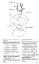
1) Carefully slip glass against ring on bottom of fixture body so that spacers
and threaded studs slip through hole in glass.
2) Hold bottom ring in place against glass so that threaded studs protrude
through holes in ring and secure in place with finials. (Do not overtighten.)
3) Turn off power.
4) Install canopy mounting screws, finger tight.
5) Loctite® threaded pipe from parts bag approximately 1/2” into stem.
6) Slip canopy then mounting strap over stem(s) assembled to fixture.
7) Loctite® ball swivel to threaded pipe. (Thread ball onto pipe until snug
against stem) Secure ball swivel in place by threading a hexnut onto
threaded pipe inside ball.
8) Lift mounting strap up against ball swivel, aligning slot in ball with tab in
strap. Snap ball retainer into place. Placing one side of ball retainer in
place and then snapping
the other in is suggested.
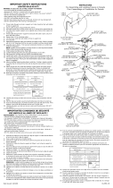
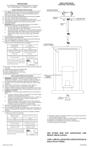
9) Attach assembled fixture/mounting strap to outlet box. Assemble
mounting strap to ceiling with ball slot and tab towards lower portion of
slope in ceiling. (REF: Illustration A)
10) Connect fixture ground wire to outlet box ground wire with wire
connectors (not provided). Never connect ground wire to black or
white power supply wire.
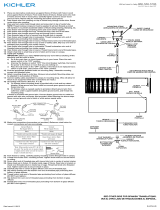
11) Make wire connections (connectors not provided.) Reference chart below
for correct connections and wire accordingly.
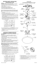
12) Carefully slip canopy up stem and secure to ceiling using lockwashers
and ball knobs.
NOTE: Loctite® must be applied to all stem threads as noted to prevent
accidental rotation of fixture during cleaning,relamping, etc.
Date Issued 8/27/02
IS-2640-CB
1) Glisser avec précautions l’abat-jour contre la couronne à la partie
inférieure du corps du lustre de façon à ce que les entreroises et les
bouons filetés passent dans le trou de l’abat-jour en verre.
2) Maintenir la couronne inférieure en place contre l’abat-jour en verre de
façon à ce que les boulons filetés dépassent des trous de l’anneau et
visser en place à l’aide des boutons décoratifs. (Ne pas trop serrer)
3) Couper l’alimentatioan électrique.
4) Installer les vis de montage de l’écran, serrer à la main.
5) Visser le tube fileté dans la tige sur environ 1, 2 cm (1/2 po).
6) Glisser l’écran puis la pate de montage sur la/les tige(s) montée(s) sur
l’élément.
7) Visser la boule orientable dans le tube fileté (jusqu’à ce qu’elle touche
la tige.) Maintenir en place en vissant un écrou à six pans à l’intérieur
de la boule.
8) Soulever la patte de montage contre la boule orientable, aligner la fente
de la boule avec la languette de la patte de montage. Il est conseillé de
mettre d’abord en place un côté du logement de la boule puis le second.
9) Fixer l’élément et la patte de montage à la boîte de jonction. Fixer la
patte de montage au plafond, la fente de la boule et la languette dirigées
vers la partie inférieure du plafond incliné. (Voir l’illustration A).
10) Connecter le câble à celui de la boîte de jonction avec des connecteurs
de câble (non fournis). Ne jamais connecter le câble de mise à la terre
au câble d’alimentation électrique noir ou blanc.
11) Connecter les câbles (connecteurs non fournis). Voir le tableau ci-
dessous ou s’adresser à un électricien qualifié pour faire les connec-
tions.
12) Glisser avec précaution l’écran sur la tige et fixer au plafond avec des
rondelles d’arrêt et des boutons ronds.
REMARQUE: Le Loctite® doit être utilisé pour tous les filetages des
tubes pour éviter que l’élément ne tourne au cours du
nettoyage, d’un changement d’ampoule, etc.
OUTLET BOX
BOITE DE JONCTION
Connecter le fil noir ou
rouge de la boite
Connecter le fil blanc de la boîte
A Noir A Blanc
*Au cordon parallèle (rond et lisse)
*Au cordon parallele (à angles droits el strié)
Au bransparent, doré, marron, ou
noir sans fil distinctif
Au transparent, doré, marron, ou
noir avec un til distinctif
Fil isolé (sauf fil vert) avec
conducteur en cuivre
Fil isolé (sauf fil vert) avec
conducteur en argent
*Remarque: Avec emploi d’un fil paralléle
(SPT I et SPT II). Le fil neutre est á angles
droits ou strié et l’autre fil doit étre rond ou
lisse (Voir le schéma).
Fil Neutre
Connect Black or
Red Supply Wire to:
Connect
White Supply Wire to:
Black White
*Parallel cord (round & smooth) *Parallel cord (square & ridged)
Clear, Brown, Gold or Black
without tracer
Clear, Brown, Gold or Black
with tracer
Insulated wire (other than green)
with copper conductor
Insulated wire (other than green)
with silver conductor
*Note: When parallel wires (SPT I & SPT II)
are used. The neutral wire is square shaped
or ridged and the other wire will be round in
shape or smooth (see illus.)
Neutral Wire
GLASS
VERRE
TRIM RING
GARNITURE
FIXTURE
ELEMENT
THREADED STUDS
VIS FILETEES
KNURL KNOBS
BOUTONS MOLETES
HEXNUT
ECROU A SIX
PANS
MOUNTING
STRAP
PATTE DE
MONTAGE
BALL RETAINER
LOGEMENT DE LA
BOULE
SLOT
FENTE
CUPPED WASHER
RONDELLE A
CUVETTE
GREEN
GROUND
SCREW
VIS VERTE
DE MISE A
LA TERRE
CANOPY
MOUNTING SCREW
VIS DE MONTAGE
DE L’ECRAN
BALL SWIVEL
BOULE ORI-
ENTABLE
CANOPY
ECRAN
THREADED PIPE
TUBE FILETE
STEM
TIGE
BALL KNOB
BOUTON ROND
SLOPED CEILING
PLAFOND INCLINE
SLOT AND TAB
FENTE ET
LANGUETTE
SCREW NOT
PROVIDED
VIS
NON FOURNI
LOCKWASHER
RONDELLE
D’ARRET
INSTRUCTIONS
For Assembling and Installing Fixtures in Canada
Pour L’assemblage et L’installation Au Canada
-
 1
1

Kichler Lighting 2640NI Manuel utilisateur
- Taper
- Manuel utilisateur
dans d''autres langues
- English: Kichler Lighting 2640NI User manual
Documents connexes
-
 Kichler Lighting 2641NI Manuel utilisateur
-
 Kichler Lighting 8880NI Manuel utilisateur
-
 Kichler Lighting 42123CH Manuel utilisateur
-
 Kichler Lighting 3278AP Manuel utilisateur
-
 Kichler Lighting 2055NI Manuel utilisateur
-
 Kichler Lighting 2655NI Manuel utilisateur
-
 Kichler Lighting 3275NI Manuel utilisateur
-
 Kichler Lighting 2643NI Manuel utilisateur
-
 Kichler Lighting 43754AUB Manuel utilisateur
-
 Kichler Lighting 42549CLP Manuel utilisateur


