Wells Manufacturing HDTG-2430G Mode d'emploi
- Catégorie
- Plaques électriques
- Taper
- Mode d'emploi
Ce manuel convient également à

WELLS BLOOMFIELD, LLC
2 ERIK CIRCLE, P. O. Box 280 Verdi, NV 89439
www.wellsbloomfield.com
PRINTED IN CHINA
telephone: 775-689-5703
fax: 775-689-5976
IMPORTANT: DO NOT DISCARD THIS MANUAL
This manual is considered to be part of the appliance and is to be given to the OWNER or
MANAGER of the restaurant, or to the person responsible for TRAINING OPERATORS of
this appliance. Additional manuals are available from your WELLS DEALER.
THIS MANUAL MUST BE READ AND UNDERSTOOD BY ALL PERSONS USING OR
INSTALLING THIS APPLIANCE. Contact your WELLS DEALER if you have any
questions concerning installation, operation or maintenance of this equipment.
OPERATION MANUAL
HEAVY DUTY
GAS GRIDDLE
MODELS
HDTG-2430G
HDTG-3630G
HDTG-4830G
Includes
INSTALLATION
USE & CARE
123
p/n 307735 Rev. (-) ECN-13411 M123 080623 cps
FOR YOUR SAFETY
Do not store gasoline or other flammable liquids
in the vicinity of this or any other appliance.
WARNING:
Improper installation, adjustment, alteration, service or maintenance can cause
property damage, injury or death. Read the installation, operating and mainte-
nance instructions thoroughly before installing or servicing this equipment.
IMPORTANT:
The purchaser of this equipment must post in a prominent location instructions to be followed in the
event the user smells gas. This information shall be obtained by consulting the local gas supplier.
Model HDTG-2430G

ENGLISH
Unless otherwise specified, all commercial cooking
equipment manufactured by WELLS BLOOMFIELD, LLC is
warranted against defects in materials and workmanship for
a period of one year from the date of original installation or
18 months from the date of shipment from our factory,
whichever comes first, and is for the benefit of the original
purchaser only.
THIS WARRANTY IS THE COMPLETE AND ONLY
WARRANTY, EXPRESSED OR IMPLIED IN LAW OR IN
FACT, INCLUDING BUT NOT LIMITED TO, WARRANTIES
OF MERCHANTABILITY OR FITNESS FOR ANY
PARTICULAR PURPOSE, AND/OR FOR DIRECT,
INDIRECT OR CONSEQUENTIAL DAMAGES IN
CONNECTION WITH WELLS BLOOMFIELD PRODUCTS.
This warranty is void if it is determined that, upon inspection
by an authorized service agency, the equipment has been
modified, misused, misapplied, improperly installed, or
damaged in transit or by fire, flood or act of God. It also
does not apply if the serial nameplate has been removed, or
if service is performed by unauthorized personnel. The
prices charged by Wells Bloomfield for its products are
based upon the limitations in this warranty. Seller’s
obligation under this warranty is limited to the repair of
defects without charge by a Wells Bloomfield factory
authorized service agency or one of its sub-service
agencies. This service will be provided on customer’s
premises for non-portable models. Portable models (a
device with a cord and plug) must be taken or shipped to
the closest authorized service agency, transportation
charges prepaid, for service. In addition to restrictions
contained in this warranty, specific limitations are shown in
the Service Policy and Procedure Guide. Wells Bloomfield
authorized service agencies are located in principal cities.
This warranty is valid in the United States and Canada and
void elsewhere. Please consult your classified telephone
directory, your foodservice equipment dealer or contact:
Service Department, Wells Bloomfield, LLC
P.O. Box 280, Verdi, Nevada 89439
phone (775) 689-5707 or fax (775) 689-5976
for information and other details concerning warranty.
LIMITED WARRANTY STATEMENT
SERVICE POLICY AND PROCEDURE GUIDE and ADDITIONAL WARRANTY EXCLUSIONS
NOTE: For your protection, please note that equipment in
this shipment was carefully inspected and packaged by
skilled personnel before leaving the factory. Upon
acceptance of this shipment, the transportation company
assumes full responsibility for its safe delivery.
IF SHIPMENT ARRIVES DAMAGED:
1. VISIBLE LOSS OR DAMAGE: Be certain that any
visible loss or damage is noted on the freight bill or
express receipt, and that the note of loss or damage is
signed by the delivery person.
2. FILE CLAIM FOR DAMAGE IMMEDIATELY:
Regardless of the extent of the damage.
3. CONCEALED LOSS OR DAMAGE: if damage is
unnoticed until the merchandise is unpacked, notify the
transportation company or carrier immediately, and file
“CONCEALED DAMAGE” claim with them. This
should be done within fifteen (15) days from the date
the delivery was made to you. Be sure to retain the
container for inspection.
Wells Bloomfield cannot assume liability for damage or loss
incurred in transit. We will, however, at your request, supply
you with the necessary documents to support your claim.
SHIPPING DAMAGE CLAIM PROCEDURE
xi
1. Resetting of safety thermostats, circuit breakers, over
load protectors, and/or fuse replacements are not
covered by this warranty unless warranted conditions
are the cause.
2. All problems due to operation at voltages or phase
other than specified on equipment nameplates are
not covered by this warranty.
Conversion to correct voltage and/or phase must be
the customer’s responsibility.
3. All problems due to electrical connections not made
in accordance with electrical code requirements
and wiring diagrams supplied with the equipment are
not covered by this warranty.
4. Replacement of items subject to normal wear, to
include such items as knobs, light bulbs; and, normal
maintenance functions including adjustments of
thermostats, adjustment of micro switches and
replacement of fuses and indicating lights are not
covered by warranty.
5. Damage to electrical cords and/or plug due to exposure
to excessive heat are not covered by this warranty.
6. Full use, care, and maintenance instructions supplied
with each machine. Noted maintenance and
preventative maintenance items, such as servicing and
cleaning schedules, are customer responsibility. Those
miscellaneous adjustments noted are customer
responsibility. Proper attention to preventative
maintenance and scheduled maintenance procedures
will prolong the life of the appliance.
7. Travel mileage is limited to sixty (60) miles from an
Authorized Service Agency or one of its sub-service
agencies.
8. All labor shall be performed during regular working
hours. Overtime premium will be charged to the buyer.
9. All genuine Wells replacement parts are warranted for
ninety (90) days from date of purchase on non-
warranty equipment. This parts warranty is limited only
to replacement of the defective part(s). Any use of
non-genuine Wells parts completely voids any
warranty.
10. Installation, labor, and job check-outs are not
considered warranty and are thus not covered by this
warranty.
11. Charges incurred by delays, waiting time or operating
restrictions that hinder the service technician’s ability to
perform service are not covered by warranty. This
includes institutional and correctional facilities.
123 307735 OpManual for HDTG-Series Griddles

ENGLISH
ENGLISH
WARRANTY xi
SPECIFICATIONS 1
FEATURES & OPERATING CONTROLS 2
PRECAUTIONS & GENERAL INFORMATION 3
AGENCY LISTING INFORMATION 3
INSTALLATION 4
OPERATION 8
CLEANING INSTRUCTIONS 10
TROUBLESHOOTING SUGGESTIONS 12
PARTS & SERVICE 13
CUSTOMER SERVICE DATA 13
FRANÇAIS
DESCRIPTION ET AVERTISSEMENTS DE SÛRETÉ 14
SPÉCIFICATIONS 15
FONCTIONNALITÉS ET COMMANDES 16
PRÉCAUTIONS & RENSEIGNEMENTS D’ORDRE
GÉNÉRAL 17
INFORMATIONS CONCERNANT LES AGENCES 17
INSTALLATION 18
FONCTIONNEMENT 22
INSTRUCTIONS POUR LE NETTOYAGE 24
CONSEILS POUR LE DÉPANNAGE 26
Thank You for purchasing this Wells Bloomfield appliance.
Proper installation, professional operation and consistent maintenance of this appliance will ensure that it
gives you the very best performance and a long, economical service life.
This manual contains the information needed to properly install this appliance, and to use and care for the
appliance in a manner which will ensure its optimum performance.
TABLE OF CONTENTS
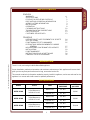
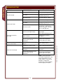
SPECIFICATIONS
INTRODUCTION
1
MODEL STYLE FUEL
MANIFOLD
PRESSURE
B.T.U.
per HOUR
HDTG-2430G
2 Dual Burners w/
Individual Control
Natural Gas 5.0” W.C.
60,000
Propane (LP) 10” W.C.
HDTG-3630G
3 Dual Burners w/
Individual Control
Natural Gas 5.0” W.C.
90,000
Propane (LP) 10” W.C.
HDTG-4830G
4 Dual Burners w/
Individual Control
Natural Gas 5.0” W.C.
120,000
Propane (LP) 10” W.C.
123 307735 OpManual for HDTG-Series Griddles

ENGLISH
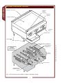
FEATURES & OPERATING CONTROLS
2
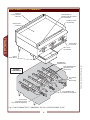
Fig. 1 HDTG Heavy Duty Gas Griddle - Features & Operating Controls
ADJUSTABLE
LEG
GREASE TRAY
CONTROL
VALVE
COOKING SURFACE
GREASE
TROUGH
GREASE
CHUTE
OPENING
INTERIOR
COMPONENTS
BURNER ASSEMBLIES
PILOT
LIGHTS
THERMOSTATIC
CONTROL VALVE
(typical)
PILOT ADJUST
EXHAUST GAS FLUE
THERMOBULB
ASSEMBLIES
123 307735 OpManual for HDTG-Series Griddles

ENGLISH
This appliance is intended for use in commercial establishments
only.
This appliance is intended
to prepare food for human consumption.
No other use is
recommended or authorized by the manufacturer or its
agents.
This appliance must be installed by a technician qualified and certified
or licensed to install gas-fired equipment. A licensed technician must
perform the initial start-up and adjustment of the appliance.
Operators of this appliance must be familiar with the appliance use,
limitations and associated restrictions. Operating instructions must be
read and understood by all persons using or installing this appliance.
Cleanliness of this appliance is essential to good sanitation. Read and
follow all included cleaning instructions and schedules to ensure the
safety of the food product.
DO NOT submerge appliance or burners in water. This appliance is
not jet stream approved. DO NOT direct water jet or steam jet at this
appliance, or at any control. DO NOT splash or pour water on, in or
over any controls. DO NOT wash counter around this appliance with
water jet. Burners which have become wet must be thoroughly dried
before use.
Griddle surface will be very hot when in use. Contact will cause severe
injury.
This appliance must be operated with the supplied 4” legs properly
installed.
Do not operate this appliance if the smell of gas is present. Turn off
all gas supply valves and move to a remote location to call your
Authorized Wells Service Agent for service.
The technical content of this manual, including any parts breakdown
illustrations and/or adjustment procedures, is intended for use by
qualified technical personnel only.
Any procedure which requires the use of tools must be performed by a
qualified technician.
This manual is considered to be a permanent part of the appliance.
This manual and all supplied instructions, diagrams, schematics, parts
breakdown illustrations, notices and labels must remain with the
appliance if it is sold or moved to another location.
This appliance conforms to NSF Standard 4 for sanitation only if
installed in accordance with the supplied Installation Instructions and
maintained according to the instructions in this manual.
This appliance meets ANSI Z.83.11 specifications for gas-fired food
service equipment.
This appliance is Canadian Standards Association design certified for
gas operation
WARNING:
FIRE HAZARD
All servicing of the gas
supply and combustion
components of this appliance
must be performed by a
technician trained and
certified in the maintenance
of gas appliances.
Improper servicing of gas
equipment can result in fire
and explosion.
CAUTION:
HOT SURFACE
Exposed surfaces can be hot
to the touch and may cause
burns.
STD 4
AGENCY LISTING INFORMATION
PRECAUTIONS AND GENERAL INFORMATION
3
123 307735 OpManual for HDTG-Series Griddles

ENGLISH
INSTALLATION
NOTE: DO NOT discard
the carton or other packing
materials until you have
inspected the appliance for
hidden damage and tested it
for proper operation.
Refer to SHIPPING DAMAGE
CLAIM PROCEDURE on the
inside front cover of this
manual.
DANGER:
HEALTH
HAZARD
This appliance must be
properly ventilated. Failure to
provide and maintain proper
ventilation of exhaust gasses
can result in severe injury or
death.
WARNING:
FIRE HAZARD
Do not store gasoline or
any other flammable or
combustible material near this
appliance. The open flame
can cause such materials to
ignite.
The area where the griddle is
installed must be kept clear of
combustibles and flammables.
This includes mops, rags,
grease, wrapping paper and
electric cords.
NOTICE: Manufacturer’s
warranty on this griddle is in
effect only when the griddle is
installed in accordance with
these instructions and local
codes and ordinances or, in
the absence of local codes,
the National Fuel Gas Code,
ANSI Z223.1 (current edition).
The manufacturer of this
griddle assumes no liability for
any damage or injury resulting
from failure to comply with this
notice.
UNPACKING & INSPECTION
Carefully remove the appliance from the carton. Remove all
protective plastic film, packing materials and accessories from the
appliance before connecting performing any installation procedure.
Carefully read all instructions in this manual and the Installation
Instruction Sheet packed with the appliance before starting any
installation.
Read and understand all labels and diagrams attached to the
appliance.
Carefully account for all components and accessories before
discarding packing materials. Store all accessories in a convenient
place for later use.
COMPONENTS
Dual Burner (-2430G, 2 ea.; -3630G, 3 ea.; -4830H, 4 ea.)
Adjustable Legs (set of 4)
Grease Tray (-2430G, 1 ea.; -3630G, 1 ea.; -4830H, 2 ea.)
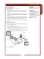
SETUP
Setup the griddle only on a firm, level, non-combustible surface.
Verify local codes for requirements. Concrete, tile, terrazzo or metal
surfaces are recommended. Metal or tile over combustible material
may not meet code for non-combustible surfaces.
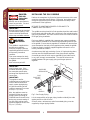
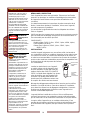
Install the provided adjustable
legs, one on each corner of the
appliance, in the holes provided.
Verify that the unit sits firmly ON
ALL FOUR LEGS. With the
adjustable legs, adjust as
required to level the appliance.
All four legs must be adjusted to
firmly contact the countertop in
order to prevent tipping.
Adequate clearance for air openings in the cabinet must be provided.
Refer to the Installation Instruction Sheet for required clearances.
Maintain required clearances between the appliance and adjacent
combustible surfaces.
The griddle must be installed in an area with sufficient make-up air
for proper combustion, and must be installed such that the flow of
combustion and ventilation air will not be obstructed.
When used with an exhaust fan, special precautions must be
observed to avoid interference with the operation of the griddle, such
as drafts and air starvation.
4
123 307735 OpManual for HDTG-Series Griddles

ENGLISH
GAS APPLIANCE CODE COMPLIANCE
The installation of gas piping from the outlet side of the gas meter or
service regulator to the griddle must be performed by a technician
qualified and certified or licensed to install gas-fired equipment.
A licensed and qualified technician must perform the initial startup and
adjustment of this appliance.
The installation of this gas-fired appliance must conform to local codes,
or in the absence of such codes, with the current edition of
National Fuel Gas Code ANSI Z223.1.
For use in the State of Massachusetts, this appliance must be installed
in compliance with Massachusetts Fuel Gas and Plumbing Code
CMR 248.
The installation of this gas-fired appliance must comply with
applicable portions of NFPA 96 for ventilation. The current edition of
NFPA 96 (Standard for the Installation of Equipment for the Removal
of Smoke and Grease Laden Vapors from Commercial Cooking
Equipment) specifies ventilation requirements to ensure the removal
of exhaust gasses and products of combustion.
IT IS THE RESPONSIBILITY OF THE INSTALLER TO ENSURE
THAT THIS GAS GRIDDLE INSTALLATION CONFORMS TO ALL
APPLICABLE CODES AND ORDINANCES.
The venting of this appliance must not be obstructed, nor may such
venting interfere with the flow of combustion air required for proper
operation of the gas burners.
Additionally:
1. The gas supply line used to connect the griddle to the gas
supply system must be black iron pipe, or other material as
approved by local ordinance for gas piping.
2. Gas supply piping must be inside 3/4” diameter or greater.
3. Use pipe sealant made specifically for gas piping on all pipe joints.
Apply sealant sparingly to the male threads only
.
Sealant must be resistant to the action of LP gas.
4. Verify that all supply piping is clean and free of obstructions, dirt,
chips and pipe sealant compound prior to installation.
5. All pipe joints must be checked for leaks before lighting. Leak
checks should be performed with a soap and water solution.
NEVER CHECK FOR LEAKS WITH AN OPEN FLAME.
INSTALLATION (continued)
5
DANGER:
FIRE AND
EXPLOSION
HAZARD
NEVER use an open flame to
check for gas leaks. Fire and
explosion may result.
WARNING:
RISK OF INJURY
Installation procedures must
be performed by a qualified
technician with full knowledge
of all applicable gas-fired
appliance codes. Failure can
result in personal injury and
property damage.
IMPORTANT:
All pipe joints must be
checked for leaks before
lighting. Leak checks should
be performed with a soap and
water solution.
IMPORTANT:
Information on the
construction and installation
of ventilating hoods may be
obtained from the current
edition of NFPA 96
Standard for the Installation
of Equipment for the Removal
of Smoke and Grease Laden
Vapors from Commercial
Cooking Equipment.
Copies of this standard are
available from the
Nation Fire Protection Assn.:
NFPA
1 Batterymarch Park
P.O. Box 9101
Quincy, MA 02269-9101
123 307735 OpManual for HDTG-Series Griddles

ENGLISH
INSTALLATION (continued)
6
INSTALLING THE GAS GRIDDLE
Refer to the nameplate. Verify the fuel type and pressure, which must
match the nameplate specifications. Connecting the hotplate to the
wrong fuel type and/or pressure will compromise the safety and/or
performance of the appliance.
BE SURE TO MAINTAIN REQUIRED CLEARANCES TO
COMBUSTIBLE SURFACES.
The griddle must be placed in its final operational position and leveled
front-to-back and side-to-side, with a spirit level, prior to beginning the
gas piping installation. Re-check the level of the unit at the conclusion
of the gas piping installation.
Each gas griddle is supplied with a separate gas pressure regulator,
which must be installed on the manifold pipe protruding from the rear
of the griddle. Ensure that the regulator is installed such that the flow
arrow stamped on the body of the regulator points toward the griddle.
Failure to properly install the supplied regulator will result in an ex-
tremely hazardous condition.
A moisture trap (drip leg) consisting of a tee, 4” nipple pointing down,
and cap must be installed upstream of the gas pressure regulator.
A manual gas shut-off valve may be required by local codes and is,
in any case, strongly recommended. The shut-off valve must be
installed between the gas supply piping and the gas pressure
regulator.
It is the responsibility of the gas piping installer to identify the code
requirement for a shut-off valve.
Shut-off valves, moisture trap and all associated piping must be
supplied by the gas piping installer.
DANGER:
FIRE AND
EXPLOSION
HAZARD
NEVER use an open flame to
check for gas leaks. Fire and
explosion may result.
IMPORTANT:
All pipe joints must be checked
for leaks before lighting. Leak
checks should be performed
with a soap and water solution.
WARNING:
FIRE HAZARD
This griddle is supplied with a
gas pressure regulator.
Failure to properly install the
supplied regulator will result in
an extremely hazardous
condition.
Flow arrow stamped on body
of regulator must point toward
the griddle.
Vent hole must point UP.
IMPORTANT:
Verify fuel gas type. If the
available fuel does not match
the nameplate specification,
exchange the hotplate for the
correct type.
IMPORTANT:
The appliance and its
individual manual shutoff valve
must be disconnected from
supply system piping during
any pressure testing of that
system at pressures in excess
of 1/2 p.s.i. (3.5 kPa).
Also, the appliance must be
isolated from the gas supply
piping system by closing its
individual manual shutoff valve
during any pressure testing of
the gas supply piping at test
pressures equal to or less than
1/2 p.s.i. (3.5 kPa).
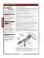
Fig. 2 Gas Supply Piping
FLOW
DRIP LEG*
GAS
SHUT-OFF
VALVE*
SUPPLIED
REGULATOR
* by others
BACK OF GRIDDLE
GAS
SUPPLY*
VENT
123 307735 OpManual for HDTG-Series Griddles

ENGLISH
INSTALLATION (continued)
7
SET GAS PRESSURE:
Gas pressure regulator is factory set.
SET PILOT FLAME:
Remove all burner control knobs, then remove the front panel.
The pilot adjustments are near the control valve for each set of
burners.
Using a small, flat-blade screwdriver, turn the screw clockwise to
decrease the flame size, or counter-clockwise to increase the
flame size.
Adjust the pilot flame to 1/4” high. Test for operation: all sections
of the burner must light without undue delay. Drafty conditions
may require a higher flame to allow the pilot to remain lit.
Replace the front panel and all knobs before returning the unit to
service.
ADJUST BURNER FLAME:
Remove all burner control knobs, then remove the front panel.
Turn an individual burner on.
Loosen the locking screw on the shutter.
Turn the shutter to admit more or less air as required. Adjust the
air shutter until the flame is mostly blue in color.
Tighten the locking screw when finished. Replace the front panel
and all knobs before returning the unit to service.
Fig. 3 Flame Adjustments
IMPORTANT:
Adjustments must be performed
by a qualified technician only.
IMPORTANT:
The griddle is shipped from
the factory equipped for natural
gas and adjusted for sea level
to 2000 feet elevation.
For conversion to LP / Propane,
or for operation above 2000 feet
elevation, contact your
Authorized Wells Service
Agency.
LESS
FLAME
MORE
FLAME
MORE AIR
LOCKING
SCREW
LESS
AIR
SHUTTER
PILOT
FLAME
ADJUST
BURNER
FLAME
ADJUST
BURNER
CONTROL
KNOB
PILOT
FLAME
ADJUST
123 307735 OpManual for HDTG-Series Griddles

ENGLISH
OPERATION
GENERAL OPERATIONAL NOTES
Carefully read the description of the griddle operation on the
specification sheet.
Do NOT use this appliance if it has been submerged in water.
Call a qualified technician to examine the appliance and to service
or replace any component which has been submerged. Burners
which have been allowed to become wet must be thoroughly dried
before use.
For initial startup, and any time the gas supply has been shut-off, it
may take several minutes to light the pilot while air in the piping and
manifolds is purged.
The burner control knobs must be turned by hand only. Never use
tools to turn the control knob. If the knob will not turn by hand, DO
NOT attempt to force or repair it. Contact your Authorized Wells
Service Agency for repairs. Forced or improperly repaired valves
pose the risk of fire and/or explosion.
Make sure burners, pilot burner and grease tray are properly installed
before attempting to operate.
LIGHTING THE PILOT FLAME
Before lighting the pilot light, smell all around the appliance area for
gas. Be sure to smell near floor level because some gas is heavier
than air and will settle to the floor.
For initial startup, and any time the gas supply has been shut-off, it
may take several minutes to light the pilot while air in the piping and
manifolds is purged.
The pilot light must be lighted by hand:
Turn all control knobs to the full OFF position.
The pilot is located adjacent to one leg of the burner, and is
accessible through the front panel opening.
Be sure the gas shut-off valve is ON and the appliance has had
time for the air to be purged from the lines. Attempt to light the
pilot every 15 seconds after the gas valve is turned on.
Light the pilot with a long match or fireplace lighter.
DO NOT use a cigarette lighter.
SHUT DOWN INSTRUCTIONS
Turn all burner knobs to OFF.
Turn all pilots OFF.
Turn the main gas supply OFF.
WARNING:
FIRE HAZARD
IF YOU SMELL GAS:
¤ DO NOT try to light
any appliance.
¤ DO NOT touch any
electrical switch
¤ DO NOT use any
telephone in your
building.
In the event a gas odor is
detected, shut down the
unit at the main gas shut-
off valve and contact your
local gas supplier from a
neighboring location.
Follow the instructions
received from the gas
supplier immediately
and exactly.
8
123 307735 OpManual for HDTG-Series Griddles

ENGLISH
WARNING:
FIRE HAZARD
NEVER attempt to force or
repair a stuck control valve.
Contact your Authorized Wells
Service Agency for repairs.
Forced or improperly repaired
valves pose the risk of fire and/
or explosion.
WARNING:
FIRE AND
EXPLOSION
HAZARD
If the pilot light should be
extinguished, turn off the gas
shut-off valve. Allow the
appliance to vent for five
minutes before attempting to
re-light.
CAUTION:
HOT SURFACE
Exposed surfaces can be hot
to the touch and may cause
burns.
OPERATION (continued)
SEASON THE GRIDDLE SURFACE
As manufactured, the steel surface of your Wells griddle has
microscopic pores. It is important to fill these pores with oil in order to
provide a hard, non-stick cooking surface.
a. Preheat the griddle surface to 375ºF (191ºC).
b. Spread a light film of cooking oil over the entire griddle surface
c. Allow the oil film to cook in for approximately 2 minutes, or until
it smokes.
d. Wipe the griddle surface with a clean damp cloth until all oil is
removed.
e. For new griddles, repeat this procedure 2-3 times until the
griddle has a slick, clean surface.
OPERATION
Inspect the unit for cleanliness before use. Clean as necessary: See
Cleaning Instructions, page 10.
Be sure the pilot light is lit before operation. See Lighting the Pilot
Light, page 8.
The burner control knobs must be turned by hand only. Never use
tools to turn the control knob.
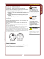
The control used in this gas griddle provides a continuous range of
settings from approximately 200ºF (93ºC) to 450ºF (230ºC).
Light the burner by turning the control knob to the highest setting until
fire forms completely in all sections of the burner. Set the control knob
to the desired temperature. The setting can be readjusted at any time.
Turn knob folly colckwise to turn burner off.
Cooking Recommendations:
Save energy by turning the temperature control knob OFF any time the
griddle is not in use. Gas burners provide full heat instantly, making it
unnecessary to leave the unit on during intermittent use.
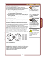
Fig. 4 Burner Control
9
200
200
300
300
350
350
250
250
400
400
450
450
OFF POSITION SET TO 350ºF≈
123 307735 OpManual for HDTG-Series Griddles

ENGLISH
CLEANING INSTRUCTIONS
PREPARATION
Turn control valve to a low setting before cleaning.
Allow griddle to cool to this lower setting before cleaning.
FREQUENCY
Daily
TOOLS
Bristle Brush
Clean Cloth or Sponge
Mild Detergent
Cleaner Formulated for Stainless Steel
Warm Water
DAILY CLEANING
1. Pour a small amount of water on the griddle surface and let it
"sizzle".
2. Clean the griddle surface. Use a pumice stone or griddle brick to
scrape food waste. Clean the griddle surface down to bright metal.
Wipe off any remaining powder residue.
IMPORTANT: NEVER USE STEEL WOOL TO CLEAN THE
GRIDDLE SURFACE!
DO NOT use detergent or oven cleaner to clean the griddle surface.
3. Use a soft-bristled fiber brush in a circular motion to remove any
remaining food particles.
4. Turn temperature control to OFF. Allow the griddle surface to cool,
then wipe the surface with a clean cloth. Dry the griddle surface
thoroughly.
IMPORTANT: SEASON THE COOKING SURFACE AFTER EACH
CLEANING. See page 9.
5. At least once each day, the grease trough must be thoroughly
cleaned. Using a scraper, remove all grease and food waste from
the grease trough by pushing it down the waste hole and into the
grease tray.
6. After scraping all cooking waste from grease trough into the grease
tray, take the grease drawer to the kitchen cleaning area and
properly dispose of all waste.
a. Clean drawer with hot water and a mild detergent.
b. Dry drawer thoroughly and reinstall in griddle.
7. Wipe down exterior of griddle cabinet with a clean cloth and non-
abrasive cleanser. Rinse thoroughly with water and a clean cloth.
Dry with a soft clean cloth.
Procedure is complete.
WARNING:
FIRE HAZARD
Shut off the gas supply
valve before cleaning.
CAUTION:
BURN HAZARD
Allow hotplate to cool
completely before
cleaning.
IMPORTANT: DO NOT spill
or pour water into controls.
DO NOT submerge griddle
cabinet in water. Damage to
internal components will
occur.
Damage to internal
components from water
damage is NOT covered by
warranty.
DO NOT steel wool or
metal scouring pads to clean
cabinet or grease tray.
Good sanitation is vital to the
quality of the final food
product. Be sure to clean in
all corners and crevices
where grease and other
cooking debris can
accumulate.
10
123 307735 OpManual for HDTG-Series Griddles

ENGLISH
PREPARATION
Turn gas shut-off valve OFF.
Allow griddle to cool before cleaning.
FREQUENCY
As Needed
TOOLS
Bristle Brush
Clean Cloth or Sponge
Mild Detergent
Cleaner Formulated for Stainless Steel
Warm Water
CLEANING BURNERS
If one or more individual flame openings does not light, or if the flame
is intermittent or uneven, the burner may need to be cleaned.
Turn shut-off valve OFF. Remove all control knobs and remove front
panel.
Note position of burner assemblies in cabinet. Remove burners.
Examine burner assemblies. Note position of air shutters before
cleaning. Clean food particles from burners with warm water, mild
detergent and a bristle brush. Rinse by wiping with a soft cloth
dampened with clean water. Wipe exterior surfaces dry with a soft
clean cloth. Allow burners to air dry so that interior passages are
completely free of water.
Examine burners to be sure the air shutters are in their proper position.
Reinstall burners with flame openings “up”. The venturi / air shutter
slides over the nozzle of the control valve. The pegs on the rear of the
burner set in corresponding notches in the rear burner support bracket.
The pegs on the front of the burner set on the front support bracket.
Turn shut-off valve ON and light pilot light.
Reinstall front panel and all control knobs.
Test all burners for proper operation.
Procedure is complete.
CLEANING INSTRUCTIONS (continued)
11
WARNING:
FIRE HAZARD
Shut off the gas supply
valve before cleaning.
IMPORTANT: DO NOT spill
or pour water into burners or
controls,
DO NOT submerge griddle
cabinet in water. Damage to
internal components will
occur.
Damage to internal
components from water
damage is NOT covered by
warranty.
123 307735 OpManual for HDTG-Series Griddles

ENGLISH
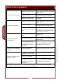
TROUBLESHOOTING
12
SYMPTOM POSSIBLE CAUSE SUGGESTED REMEDY
Pilot will not light
Gas supply off Check main / unit gas valves
Air in lines
Turn pilot valve on. Attempt to
light pilot every 15 sec.
Pilot valve not on Turn pilot valve on / adjust
Burners won’t light
Gas supply off Check main / unit gas valves
Air in lines
Turn gas valve on. Attempt to
light pilot every 15 sec.
Pilot burner not lit
Turn off gas - allow unit to
vent for 5 minutes. Turn gas
back on and light pilot
Control not set high enough
Turn control knob to desired
temperature
Set to desired setting when lit
Water in burner
Remove burner and dry
thoroughly
Damaged temperature control,
burner or other internal
component
Contact Authorized Wells
Service Agency for repairs
Portions of a burner won’t light
or have erratic flame
Burner wet or flame opening(s)
clogged
Clean and dry burner
Burner not hot enough
Temperature control not set Adjust for desired temperature
Shutter or nozzle out of
adjustment
Contact qualified technician for
adjustment
Damaged temperature control,
burner or other internal
component
Contact Authorized Wells
Service Agency for repairs
NOTE: There are no user
serviceable components in the
burner assemblies or in the
control valves. In all cases of
damage or malfunction,
contact your Authorized Wells
Service Agency for repairs.
One burner assembly
won’t light
123 307735 OpManual for HDTG-Series Griddles

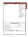
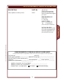
CUSTOMER SERVICE DATA
please have this information available if calling for service
RESTAURANT _____________________________ LOCATION _____________
INSTALLATION DATE ________________________ TECHNICIAN ___________
SERVICE COMPANY ________________________________________________
ADDRESS ___________________________ STATE ______ ZIP__________
TELEPHONE NUMBER (_____)_____-_________
EQUIPMENT MODEL NO. _______________
EQUIPMENT SERIAL NO. _______________
FUEL (check one) NATURAL GAS PROPANE / LP
ENGLISH
DESCRIPTION PART NO.
LEGS, ADJUSTABLE 4” METAL (SET of 4) 20563
PARTS & SERVICE
13
IMPORTANT: Use only
factory authorized service
parts .
For factory authorized
service, or to order factory
authorized replacement parts,
contact your Wells authorized
service agency, or call:
Wells Bloomfield, LLC
2 Erik Circle
P. O. Box 280
Verdi, NV 89439
Service Parts Dept.
phone: (775) 689-5707
fax: (775) 689-5976
Service Parts Department can
supply you with the name and
telephone number of the
WELLS AUTHORIZED
SERVICE AGENCY
nearest you.
123 307735 OpManual for HDTG-Series Griddles

FRANÇAIS
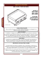
MANUEL DE L’UTILISATEUR
14
WELLS GRILL PROFESSIONNEL
MODÈLES
HDTG-2430G
HDTG-3630G
HDTG-4830G
Comprend :
INSTALLATION,
MODE D’EMPLOI
& ENTRETIEN
POUR VOTRE SÉCURITÉ
Ne pas stocker d’essence ou d'autres liquides inflammables au voisinage de cet
appareil ou autres appareils ménagers.
AVERTISSEMENT !
L’installation, le réglage, les modifications, l’entretien ou la maintenance effectués
de manière incorrecte peuvent entraîner des dommages matériels, corporels ou même
la mort. Lire attentivement les instructions relatives à l’installation, au fonctionnement,
à l’entretien et à la maintenance avant d’installer ou de réparer l’équipement.
IMPORTANT :
L’acquéreur de ce matériel doit afficher, en pleine vue du public, les instructions à
suivre en cas de détection d’une odeur de gaz par l’utilisateur. Cette information
doit être obtenue après consultation de la société locale distributrice du gaz.
IMPORTANT : NE PAS JETER CE GUIDE
Ce guide fait partie de l’appareil et doit être remis au propriétaire, au directeur du
restaurant ou à la personne responsable de la formation des utilisateurs de l’appareil.
Des guides supplémentaires sont disponibles chez votre distributeur Wells.
Ce guide doit être lu et compris par toutes personnes installant ou utilisant cet appareil.
Contacter votre distributeur Wells pour toutes questions au sujet de l’installation, du
fonctionnement ou de l’entretien de cet appareil.
Modéle HDG-3630G
123 307735 OpManual for HDTG-Series Griddles

FRANÇAIS
TABLE DES MATIÈRES
15
FRANÇAIS
DESCRIPTION ET AVERTISSEMENTS DE SÛRETÉ 14
SPÉCIFICATIONS 15
FONCTIONNALITÉS ET COMMANDES 16
PRÉCAUTIONS & RENSEIGNEMENTS D’ORDRE
GÉNÉRAL 17
INFORMATIONS CONCERNANT LES AGENCES 17
INSTALLATION 18
FONCTIONNEMENT 22
INSTRUCTIONS POUR LE NETTOYAGE 24
CONSEILS POUR LE DÉPANNAGE 26
Merci d’avoir acquis cet appareil Wells Bloomfield. L’installation correcte, le fonctionnement professionnel
et l’entretien régulier de cet appareil assureront ses meilleures performances et sa longue durée de
service aux meilleurs coûts. Le présent manuel contient l’information nécessaire pour installer
correctement l’appareil et pour l’utiliser et l’entretenir de manière à ce qu’il fonctionne avec des
performances optimales.
INTRODUCTION
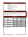
SPÉCIFICATIONS
MODÈLE STYLE COMBUSTIBLE
PRESSION DU
COLLECTEUR
CONSOMMATION
D’ÉNERGIE
TOTALE (BTU) par
heure
HDTG-1230G
2 brûleurs avec
commandes
individuelles
Gaz naturel 5.0” W.C. 53,000
Propane* 10” W.C.
HDTG-2430G
4 brûleurs avec
commandes
individuelles
Gaz naturel 5.0” W.C. 106,000
Propane* 10” W.C.
HDTG-3630G
6 brûleurs avec
commandes
individuelles
Gaz naturel 5.0” W.C. 159,000
Propane* 10” W.C.
43,000
86,000
129,000
*Propane (gaz de pétrole liquide--GPL)
123 307735 OpManual for HDTG-Series Griddles

FRANÇAIS
FONCTIONNALITÉS ET COMMANDES
16
Fig. 5 FONCTIONNALITÉS ET COMMANDES DU GRILL PROFESSIONNEL À GAZ
INTERIOR
COMPONENTS
LES TEMPÉRATURE
SENTANTS DES
AMPOULES
PIEDS
RÉGLABLES
BAC POUR
LA GRAISSE
CONTROLER
LE BOUTON
SURFACE DE
CUISSON
PLATEAU POUR
LA GRAISSE
OUVERTURE DU
CONDUIT D'ÉVACUATION
DE LA GRAISSE
CONDUIT
D'ÉVACUATION
DES GAZ
ENSEMBLES
DE BRÛLEURS
CONTROLER
LA SOUPAPE POUR
LA FLAMME DE BRULEUR
L'AJUSTEMENT DE
FLAMME D'ALLUMAGE
ALLUMAGE
DES
BRÛLEURS
123 307735 OpManual for HDTG-Series Griddles

FRANÇAIS
Cet appareil est prévu exclusivement à l’usage des
établissements commerciaux.
Cet appareil est destiné à la cuisson d’aliments pour la consommation
humaine. Aucun autre usage n’est recommandé ni autorisé par le
fabricant ou ses agents.
Cet appareil doit être installé par un technicien qualifié ou et certifié
ou agréé pour l’installation des équipements fonctionnant au gaz. Un
technicien qualifié et agréé doit assurer la mise en service et le réglage
initiaux de l'appareil.
Les utilisateurs de l’appareil doivent être familiarisés avec l’utilisation
de l’appareil, ses limites et ses restrictions associées. Le mode
d’emploi doit être lu et compris par toutes les personnes installant ou
utilisant cet appareil.
La propreté de cet appareil est essentielle à de bonnes conditions sa-
nitaires. Lire et suivre toutes les instructions relatives au nettoyage et
aux programmes visant à assurer l’innocuité des produits alimentaires.
NE PAS submerger l’appareil ou les brûleurs dans l’eau. Cet appareil
n’est pas approuvé pour supporter les jets d’eau. NE PAS orienter
de jet d’eau ou de vapeur directement sur cet appareil ou de ses
commandes. NE PAS éclabousser ni verser d’eau sur, dans ou par
dessus les commandes. NE PAS laver le comptoir entourant l’appareil
avec un jet d’eau. Les brûleurs mouillés doivent être complètement
séchés avant usage.
Les surfaces de cuisson deviennent très chaudes pendant l’usage.
Leur contact provoquera des brûlures graves.
Cet appareil doit être utilisé avec ses pieds de 10 cm (4 po.) de haut
correctement installés.
Ne pas utiliser cet appareil en présence d’une odeur de gaz. Fermer
tous les robinets à gaz et se rendre dans un lieu éloigné pour appeler
un technicien d’entretien agréé par Wells.
La partie technique du présent manuel, y compris tous les schémas
éclatés illustrant les pièces et/ou les procédures de réglage, est
destinée exclusivement à l’usage de techniciens qualifiés.
Toute procédure exigeant l’emploi d’outils doit être accomplie par un
technicien qualifié.
Le présent manuel est considéré être une pièce permanente de
l’appareil. Ce manuel et toutes les instructions, schémas, illustrations
de pièces éclatées, notices et étiquettes fournis doivent demeurer avec
l’appareil si ce dernier est revendu ou déménagé dans un autre local.
Cet appareil n’est conforme à la Norme 4 de la fondation nationale de
normalisation sanitaire des États-Unis (National Sanitation Foundation-
-NSF) que s’il est installé conformément aux Instructions relatives à
l’installation fournies avec l’appareil et si ce dernier est entretenu selon
les instructions du présent manuel.
Cet appareil est conforme aux spécifications ANSI Z.83.11 pour les
appareils à gaz utilisés dans les établissements préparant des
aliments.
Cet appareil est d’une conception certifiée pour le fonctionnement au
gaz par l’Association canadienne de normalisation (ACN/CSA).
AVERTISSEMENT!
DANGER D’INCENDIE
Toutes les opérations
d’entretien et de réparation
des composants servant à
l’alimentation et à la
combustion du gaz dans cet
appareil doivent être
effectuées par un technicien
qualifié et agréé pour la
maintenance des appareils
à gaz. L’entretien incorrect
des appareils à gaz peut
entraîner des incendies et
des explosions.
ATTENTION:
SURFACE CHAUDE
Les surfaces exposées
peuvent être chaudes au
toucher et peuvent
occasionner des brûlures.
Norme 4
INFORMATIONS CONCERNANT LES AGENCES
PRÉCAUTIONS & RENSEIGNEMENTS D’ORDRE GÉNÉRAL
17
123 307735 OpManual for HDTG-Series Griddles

FRANÇAIS
L'INSTALLATION
REMARQUE : NE PAS jeter le
carton ni les autres matériaux
d’emballage jusqu’à ce que
l’appareil ait été inspecté pour la
détection de vices cachés et ait
subi des tests de fonctionnement
satisfaisants. Consulter la
PROCÉDURE DE RÉCLAMA-
TION EN CAS DE DOMMAGES
DUS AU TRANSPORT imprimée
sur la face interne de la première
page de couverture du présent
manuel.
DANGER:
Danger pour la
santé
Cet appareil doit être situé dans
un local correctement aéré. Le
défaut d’assurance et de maintien
d’une aération convenable avec
mise à l’évent des gaz de
combustion peut entraîner des
dommages corporels graves ou
même la mort.
AVERTISSEMENT :
Danger d’incendie
Ne pas stocker
d’essence ou d'autres matériaux
combustibles ou
inflammables à proximité de cet
appareil. Toute flamme nue peut
provoquer l’inflammation de ces
matériaux. La zone où le grill est
installé doit être dépourvue de
tout matériau combustible ou
inflammable. Ceux-ci
comprennent, notamment, les
serpillères, les lavettes ou les
chiffons, la graisse, le papier
d’emballage et les cordons
d’alimentation électriques
.
NOTICE : La garantie du
fabricant concernant cet appareil
entre en vigueur exclusivement si
l’appareil est installé
conformément aux présentes
instructions, aux dispositions de
la réglementation et des codes
locaux, ou en l’absence de codes,
de la norme ANSI Z223.1 (édition
en vigueur) du code national
relatif au gaz combustible
(National Fuel Gas Code). Le
fabricant de ce grill décline toute
responsabilité en cas de
dommages corporels ou matériels
résultant du défaut d'application
des dispositions de la présente
notice.
DÉBALLAGE & INSPECTION
Sortir l’appareil du carton avec précaution. Enlever tous les films de
protection en plastique, les matériaux d’emballage et les accessoires
de l’appareil avant d'entamer toute procédure d'installation et de
connexion.
Lire attentivement toutes les instructions du présent manuel et de la
Notice-–Instructions relatives à l’installation, incluse avec l’appareil,
avant de commencer l’installation.
Lire et assimiler la signification de toutes les étiquettes et schémas
fixés sur l’appareil.
Vérifier que tous les composants et accessoires sont présents avant de
jeter les matériaux d'emballage. Ranger tous les accessoires dans un
lieu convenable pour les utiliser plus tard.
COMPOSANTS
Double brûleur
(-2430G, 2 pièce; -3630G, 3 pièce; -4830H, 4 pièce)
Pieds réglables (jeu de 4)
Plateau pour la graisse
(-2430G, 1 pièce; -3630G, 1 pièce;
-4830H, 2 pièce)
INSTALLATION
Installer l’appareil uniquement sur une surface solide, horizontale et
non combustible. Vérifier les conditions imposées par les codes locaux.
Les surfaces en ciment, en carreaux de céramique ou de marbre, ou
en métal sont recommandées. Le métal ou les carreaux de céramique
posés sur des matériaux combustibles peuvent être incompatibles avec
les dispositions du code imposant des surfaces
non combustibles.
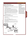
Installer les pieds fournis avec l’appareil,
un pied à chaque coin de l’appareil, dans
les trous préparés. Vérifier que l’unité est
stable et repose bien SUR LES QUATRE
PIEDS. Les pieds étant réglables, les ajuster
selon les besoins pour que l’appareil soit
horizontal. Les quatre pieds doivent être
ajustés pour faire solidement contact avec
le comptoir afin d’éviter tout basculement.
Ménager des dégagements adéquats dans l’armoire pour les orifices
d’aération. Consulter la Notice—Intructions relatives à l’installation,
pour obtenir les dimensions de dégagement obligatoires. Conserver
les distances de dégagement nécessaires entre l’appareil et les
surfaces combustibles adjacentes.
L’appareil doit être installé dans un lieu où l’air est suffisamment
renouvelé pour assurer une combustion correcte et de telle manière
que le courant de l’air de combustion et d’aération ne soit pas obstrué .
Lorsqu’on utilise l’appareil avec un ventilateur d’extraction, il faut
prendre des précautions spéciales pour éviter toute interférence avec
le fonctionnement de l’appareil, tels que courants d’air et privation
d’air .
18
FIXATION PAR
VIS DANS LE
CADRE
TOURNER
POUR
RÉGLER
LA HAUTEUR
123 307735 OpManual for HDTG-Series Griddles
La page est en cours de chargement...
La page est en cours de chargement...
La page est en cours de chargement...
La page est en cours de chargement...
La page est en cours de chargement...
La page est en cours de chargement...
La page est en cours de chargement...
La page est en cours de chargement...
La page est en cours de chargement...
La page est en cours de chargement...
-
 1
1
-
 2
2
-
 3
3
-
 4
4
-
 5
5
-
 6
6
-
 7
7
-
 8
8
-
 9
9
-
 10
10
-
 11
11
-
 12
12
-
 13
13
-
 14
14
-
 15
15
-
 16
16
-
 17
17
-
 18
18
-
 19
19
-
 20
20
-
 21
21
-
 22
22
-
 23
23
-
 24
24
-
 25
25
-
 26
26
-
 27
27
-
 28
28
-
 29
29
-
 30
30


Wells Manufacturing HDTG-2430G Mode d'emploi
- Catégorie
- Plaques électriques
- Taper
- Mode d'emploi
- Ce manuel convient également à
dans d''autres langues
Documents connexes
-
Wells Manufacturing HDTG-4830G Mode d'emploi
-
-
-
2Wire HDCR-1230G Manuel utilisateur
-
-
-
-