Velleman DVM832 Manuel utilisateur
- Catégorie
- Mesure
- Taper
- Manuel utilisateur


DVM832
V. 05 – 05/01/2022 2 ©Velleman Group nv
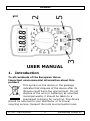
USER MANUAL
1. Introduction
To all residents of the European Union
Important environmental information about this
product
This symbol on the device or the package
indicates that disposal of the device after its
lifecycle could harm the environment. Do not
dispose of the unit (or batteries) as unsorted
municipal waste; it should be taken to a
specialized company for recycling. This device
should be returned to your distributor or to a local
recycling service. Respect the local environmental rules.

DVM832
V. 05 – 05/01/2022 3 ©Velleman Group nv
If in doubt, contact your local waste disposal
authorities.
Thank you for choosing Velleman! Please read the manual
thoroughly before bringing this device into service. If the
device was damaged in transit, do not install or use it and
contact your dealer.
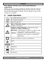
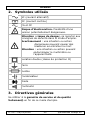
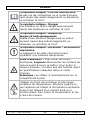
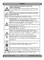
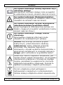
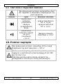
2. Used Symbols
AC (Alternating Current)
DC (Direct Current)
Both AC and DC
Risk of Electric shock. A potentially hazardous
voltage is possible.
Caution: risk of danger, refer to the user
manual for safety information.
Warning: a hazardous condition or action that
may result in injury or death
Caution: condition or action that may result in
damage to the meter or equipment
under test
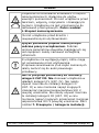
Double insulation (class 2-protection)
Earth
Fuse
Capacitor
Diode
Continuity

DVM832
V. 05 – 05/01/2022 4 ©Velleman Group nv
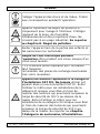
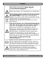
3. General Guidelines
Refer to the Velleman® Service and Quality Warranty
on the last pages of this manual.
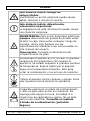
This symbol indicates: Read instructions
Not reading the instructions and manual can lead
to damage, injury or death.
This symbol indicates: Danger
A hazardous condition or action that may result in
injury or death
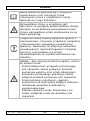
This symbol indicates: Risk of
danger/damage
Risk of a hazardous condition or action that may
result in damage, injury or death
This symbol indicates: Attention; important
information
Ignoring this information can lead to hazardous
situations.
WARNING: To avoid electrical shock always
disconnect the test leads prior to opening the
housing. To prevent fire hazards, only use fuses
with the same ratings as specified in this manual.
Remark: refer to the warning on the battery
compartment
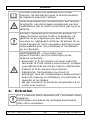
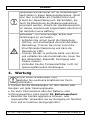
Avoid cold, heat and large temperature
fluctuations. When the unit is moved from a cold
to a warm location, leave it switched off until it
has reached room temperature. This to avoid
condensation and measuring errors.
Protect this device from shocks and abuse. Avoid
brute force when operating.

DVM832
V. 05 – 05/01/2022 5 ©Velleman Group nv
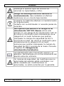
Pollution degree 2-device. For indoor use only.
Keep this device away from rain, moisture,
splashing and dripping liquids. Not for industrial
use. Refer to 8. Pollution degree.
Keep the device away from children and
unauthorised users.
Risk of electric shock during operation. Be
very careful when measuring live circuits.
There are no user-serviceable parts inside the
device.
Refer to an authorized dealer for service and/or
spare parts.
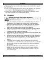
This is an installation category CAT III
measuring instrument. Never use this
equipment in a CAT IV environment. Never use
the meter with CAT II installations when
measuring voltages that might exceed the safety
margin of 500 V above earth ground. Never use
the meter with CAT III installations when
measuring voltages that might exceed the safety
margin of 300 V above earth ground. Refer to
7. Overvoltage/installation category.
Read this addendum and the manual thoroughly.
Familiarise yourself with the functions of the
device before actually using it.
All modifications of the device are forbidden for
safety reasons. Damage caused by user
modifications to the device is not covered by the
warranty.
Only use the device for its intended purpose.
Using the device in an unauthorized way will void
the warranty. Damage caused by disregard of

DVM832
V. 05 – 05/01/2022 6 ©Velleman Group nv
certain guidelines in this manual is not covered by
the warranty and the dealer will not accept
responsibility for any ensuing defects or
problems.
WARNING – To avoid electric shock, fire or
personal injury:
• Connect the common test lead before the live
test lead and remove the live test lead before
the common test lead.
• Disconnect the power and discharge all high-
voltage capacitors before you measure
resistance, continuity, capacitance or a diode
junction.
• When using the temperature probe, do not
connect the probe to live circuits.
4. Maintenance
There are no user-serviceable parts inside the
device.
Refer to an authorized dealer for service and/or
spare parts.
• Before performing any maintenance activities, disconnect
the test leads from the jacks.
• For instructions on replacing battery or fuse, refer to
15. Battery replacement.
• Do not apply abrasives or solvents to the meter. Use a
damp cloth and mild detergent for cleaning purposes.
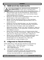
5. During Use
Risk of electric shock during operation. Be
very careful when measuring live circuits.

DVM832
V. 05 – 05/01/2022 7 ©Velleman Group nv
• Never exceed the limit value for protection. This limit
value is listed separately in the specifications for each
range of measurement.
• Do not touch unused terminals when the meter is
linked to a circuit which is being tested.
• Set the range selector at its highest position if the
intensity of the charge to be measured is unknown
beforehand.
• Disconnect the test leads from the tested circuit before
rotating the range selector in order to change
functions.
• When carrying out measurements on a TV set or
switching power circuits, always remember that the
meter may be damaged by any high amplitude voltage
pulses at test points.
• Always be careful when working with voltages above
60 VDC or 30 VAC rms. Keep your fingers behind the probe
barriers at all times during measurement.
• Never perform resistance, diode or continuity
measurements on live circuits. Make sure all capacitors
in the circuit are depleted.
6. General Description
Refer to the illustration on page 2 of this manual:
1. Display (max. 1999 counts, max. 3 ½ digits,
dimensions: 47 x 15 mm)
With low-battery indication
2. Rotary switch for manual range selection
This switch is used to select functions and desired
ranges as well as to turn the meter on/off.
3. "VmA" jack
Insert the red (positive) test lead in this connector to
measure voltage, resistance and current (except
10 A).
4. "COM" jack
Insert the black (negative) test lead.

DVM832
V. 05 – 05/01/2022 8 ©Velleman Group nv
5. "10A" jack
Insert the red test lead in this connector in order to
measure a max. current of 10 A.
Test lead probe: CAT II 500 V/CAT III 300 V, 10 A, L
= 90 cm
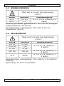
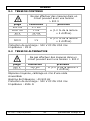
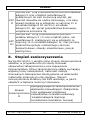
7. Overvoltage/Installation Category
The applicable categories according EN 61010-1 are:
CAT
II
A CAT II-rated meter is suitable for measurements in
CAT I-environments and mono-phase appliances that
are connected to the mains by means of a plug and
circuits in a normal domestic environment, provided
that the circuit is at least 10m apart from a CAT III-
or 20 m apart from a CAT IV-environment. E.g.
household appliances, portable tools…
CAT
III
A CAT III-rated meter is suitable for measurements
in CAT I- and CAT II-environments, as well as for
measurements on (fixed) mono- or poly-phased
appliances which are at least 10 m apart from of a
CAT IV-environment, and for measurements in or on
distribution level equipment (fuse boxes, lighting
circuits, electric ovens).
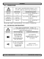
8. Pollution Degree
IEC 61010-1 specifies different types of pollution
environments, for which different protective measures are
necessary to ensure safety. Harsher environments require
more protection, and the protection against the pollution
which is to be found in a certain environment depends
mainly on the insulation and the enclosure properties. The
pollution degree rating of the DVM indicates in which
environment the device may be used.

DVM832
V. 05 – 05/01/2022 9 ©Velleman Group nv
Pollution
degree 2
Only nonconductive pollution occurs.
Occasionally, temporary conductivity caused
by condensation is to be expected. (home and
office environments fall under this category)
•This device is only suitable for measurements
in Pollution degree class 2 environments.
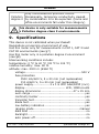
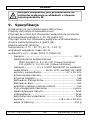
9. Specifications
This device is not calibrated when purchased!
Regulations concerning environment of use:
Use this meter only for measurements in CAT I, CAT II and
CAT III environments (see §7)
Use this meter only in a pollution degree 2 environment
(see §8)
Ideal working conditions include:
temperature: 0 °C to 40 °C (32 °F to 104 °F)
relative humidity: max. 80 %
altitude: max. 2000 m (6560 ft)
voltage .........................................................500 V
fuse protection
F500 mA/600 V, 5 x 20 mm (not replaceable)
F10 A/600 V, 5 x 20 mm (not replaceable)
power supply ................ 2 x 1.5 VDC AAA/R03P (incl.)
display ......................................... LCD, 1999 counts
display dimensions ................................ 47 x 15 mm
over-range ....................................................... yes
continuity buzzer ............................................... yes
transistor test .................................................... no
diode test ......................................................... yes
low-battery indication ........................................ yes
ranging mode ............................................. manual
data hold .......................................................... no
backlight ........................................................... no
auto power-off ................................................... no

DVM832
V. 05 – 05/01/2022 10 ©Velleman Group nv
dimensions .................................. 118 x 65 x 30 mm
weight (with battery) ...................................... 100 g
operating environment:
temperature: 0 °C to 40 °C (32 to 104 °F)
humidity: < 80 % RH.
storage environment:
temperature: -20 °C to 60 °C (-4 °F to 140 °F)
humidity: < 90 % RH
test lead probe (incl.) CAT II 500 V/CAT II 300 V, 10 A;
L = 90 cm
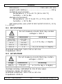
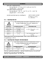
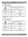
9.1 DC VOLTAGE
Do not measure circuits that may contain
voltages > 500 V
range
resolution
accuracy
200 mV
0.1 mV
± (1.0 % rdg + 2 digits)
2000 mV
1 mV
20 V
10 mV
200 V
100 mV
500 V
1 V
± (1.2 % rdg + 2 digits)
Overload protection: 500 V DC or AC rms
Impedance: 1M Ω
9.2 AC VOLTAGE
Do not measure circuits that may contain
voltages > 500 V
range
resolution
accuracy
200 V
100 mV
± (1.2 % rdg + 3 digits)
500 V
1 V
Average sensing, calibrated to rms of sine wave
Frequency range: 40-500 Hz
Overload protection: 500 V DC or AC rms
Impedance: 450k Ω

DVM832
V. 05 – 05/01/2022 11 ©Velleman Group nv
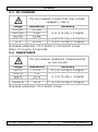
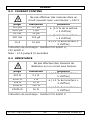
9.3 DC CURRENT
Do not measure circuits that may contain
voltages > 500 V
range
resolution
accuracy
200 µA
0.1 µA
± (1.5 % rdg + 2 digits)
2000 µA
1 µA
20 mA
10 µA
200 mA
100 µA
± (2.0 % rdg + 2 digits)
10 A
10 mA
± (2.0 % rdg + 3 digits)
Overload protection: F0.5 A/600 V, F10 A/600 V fuse
Note: 10 A up to 10 seconds
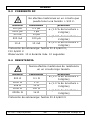
9.4 RESISTANCE
Do not conduct resistance measurements
on live circuits
range
resolution
accuracy
200 Ω
0.1 Ω
± (1.0 % rdg + 5 digits)
2000 Ω
1 Ω
± (1.0 % rdg + 3 digits)
20k Ω
10 Ω
200k Ω
100 Ω
2000k Ω
1k Ω
± (1.5 % rdg + 3 digits)
Overload protection: F0.5 A/600 V fuse

DVM832
V. 05 – 05/01/2022 12 ©Velleman Group nv
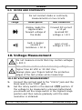
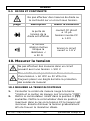
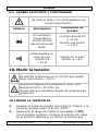
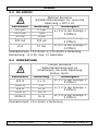
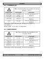
9.5 DIODE AND CONTINUITY
Do not conduct diode or continuity
measurements on live circuits
range
description
test condition
display reads the
approximate
forward voltage of
the diode
forward DC current
± 10 µA
reversed DC
voltage ± 1.8 V
built-in buzzer
sounds if
resistance < 50 Ω
open-circuit
voltage ± 1.8 V
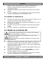
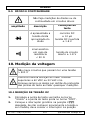
10. Voltage Measurement
Do not measure circuits that may contain voltages
> 500 V
Use extreme caution when measuring voltages
higher than 60 VDC or 30 VAC rms.
Always place your fingers behind the protective
edges of the test probes while measuring!
10.1 DC VOLTAGE MEASUREMENT
1. Connect the red test lead to the "VmA" jack and the
black lead to the "COM" jack.
2. Set the rotary switch in the desired V position. If
the voltage to be measured is unknown beforehand,
you should set the range switch in the highest range
position and then reduce gradually until the ideal
resolution is obtained.

DVM832
V. 05 – 05/01/2022 13 ©Velleman Group nv
3. Connect the test leads to the source being measured.
4. Read the voltage value on the LCD display along with
the polarity of the red lead connection.
10.2 AC VOLTAGE MEASUREMENT
1. Connect the red test lead to the "VmA" jack and the
black test lead to the "COM" jack.
2. Set the rotary switch in the appropriate V~ position.
3. Connect the test leads to the source to be measured.
4. Read the voltage value on the LCD display.
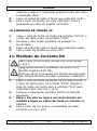
11. DC Current Measurement
Do not measure circuits that may contain voltages
> 500 V
Use extreme caution when measuring voltages
higher than 60 VDC.
Always place your fingers behind the protective
edges of the test probes while measuring!
1. Connect the red test lead to the "VmA" jack and the
black test lead to the "COM" jack (switch the red lead
to the "10A" jack for measurements between 200 mA
and 10 A).
2. Set the rotary switch (DCA) in the desired position.
3. Open the circuit in which the current is to be
measured and connect the test leads to the circuit IN
SERIES.
4. Read the current value and the polarity of the red
lead connection on the LCD display
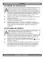
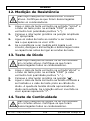
12. Resistance Measurement
Do not conduct resistance measurements on live
circuits. Make sure all capacitors in the circuit are
depleted.

DVM832
V. 05 – 05/01/2022 14 ©Velleman Group nv
1. Connect the red test lead to the "VmA" jack and the
black test lead to the "COM" jack (the red lead has a
positive polarity "+").
2. Set the rotary switch in the appropriate "" range
position.
3. Connect the test leads to the resistor to be measured
and read the LCD display.
4. If the resistance being measured is connected to a
circuit, turn off the power and discharge all capacitors
before applying the test probes.
13. Diode Testing
Do not conduct diode or continuity measurements
on live circuits. Make sure all capacitors in the
circuit are depleted.
1. Connect the red test lead to "VmA" jack and the
black one to the "COM" jack (the red lead has a
positive polarity "+".).
2. Set the rotary switch in the " " position.
3. Connect the red test lead to the anode of the diode to
be tested and the black test lead to the cathode of
the diode. The approx. forward voltage drop of the
diode will be displayed. If the connection is reversed,
the display will merely show a "1".
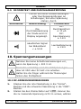
14. Continuity Testing
Do not conduct diode or continuity measurements
on live circuits. Make sure all capacitors in the
circuit are depleted.
1. Connect the red test lead to "VmA" and the black
one to "COM".
2. Set the range switch in the " " position.

DVM832
V. 05 – 05/01/2022 15 ©Velleman Group nv
3. Connect the test leads to two points of the circuit to
be tested. If continuity exists, the built-in buzzer will
sound.
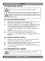
15. Battery Replacement
WARNING: To avoid electrical shock always
disconnect the test leads prior to opening the
housing. To prevent fire hazards, only use fuses
with the same ratings as specified in this manual.
Remark: refer to the warning on the battery
compartment
There are no user-serviceable parts inside the
device.
Refer to an authorized dealer for service and/or
spare parts.
Equipment must be isolated or disconnected from
the HAZARDOUS LIVE voltage before access
(referring to battery replacement by operator).
• When" " is displayed, the battery should be
replaced.
• Blown fuses almost always result from human error.
To replace the battery:
• Switch of the meter
• Release the screw located at the backside of the meter
and gently open the housing.
• Remove the old batteries and insert new ones.
Battery: 2 x 1.5 VDC AAA/R03P alkaline, do not use
rechargeable batteries and make sure to respect
the polarity
Make sure the meter is closed tight and put the protective
edge back in place before using the meter.

DVM832
V. 05 – 05/01/2022 16 ©Velleman Group nv
16. Troubleshooting
If the device beeps continuously while measuring
continuity, this means that the F500 mA/600 V internal
fuse is defective.
Keep in mind that a low battery level could lead to
incorrect measurements. Replace the batteries on a regular
basis.
Tip: the reduced luminosity of the backlight/LCD display
indicates a low battery level.
Use this device with original accessories only.
Velleman Group nv cannot be held responsible in the
event of damage or injury resulting from (incorrect)
use of this device. For more info concerning this
product and the latest version of this manual, please
visit our website www.velleman.eu. The information
in this manual is subject to change without prior
notice.
© COPYRIGHT NOTICE
The copyright to this manual is owned by Velleman
Group nv. All worldwide rights reserved. No part of
this manual may be copied, reproduced, translated or
reduced to any electronic medium or otherwise without the
prior written consent of the copyright holder.

DVM832
V. 05 – 05/01/2022 17 ©Velleman Group nv
HANDLEIDING
1. Inleiding
Aan alle ingezetenen van de Europese Unie
Belangrijke milieu-informatie betreffende dit product
Dit symbool op het toestel of de verpakking geeft aan dat,
als het na zijn levenscyclus wordt
weggeworpen, dit toestel schade kan
toebrengen aan het milieu. Gooi dit toestel (en
eventuele batterijen) niet bij het gewone
huishoudelijke afval; het moet bij een
gespecialiseerd bedrijf terechtkomen voor
recyclage. U moet dit toestel naar uw verdeler of naar een
lokaal recyclagepunt brengen. Respecteer de plaatselijke
milieuwetgeving.
Hebt u vragen, contacteer dan de plaatselijke
autoriteiten betreffende de verwijdering.
Dank u voor uw aankoop! Lees deze handleiding grondig
door voor u het toestel in gebruik neemt. Werd het toestel
beschadigd tijdens het transport, installeer het dan niet en
raadpleeg uw dealer.
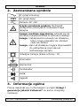
2. Gebruikte symbolen
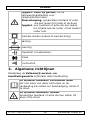
AC (wisselstroom)
DC (gelijkstroom)
Zowel wissel- als gelijkstroom
Elektrocutiegevaar. Een potentieel gevaarlijke
spanning kan aanwezig zijn.

DVM832
V. 05 – 05/01/2022 18 ©Velleman Group nv
Opgelet: risico op gevaar, zie de
gebruikershandleiding voor
veiligheidsinformatie.
Waarschuwing: gevaarlijke toestand of actie
die kan leiden tot letsel of de dood
Opgelet: een toestand of actie die kan leiden
tot schade aan de meter of het toestel
onder test.
Dubbele isolatie (klasse II-bescherming)
Aarding
zekering
Capaciteit (condensator)
Diode
Continuïteit
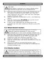
3. Algemene richtlijnen
Raadpleeg de Velleman® service- en
kwaliteitsgarantie achteraan deze handleiding.
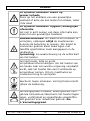
Dit symbool betekent: Instructies lezen
Het niet lezen van deze instructies en de
handleiding kan leiden tot beschadiging, letsel of
de dood.
Dit symbool betekent: Gevaar
Gevaarlijke toestand of actie die kan leiden tot
letsel of de dood

DVM832
V. 05 – 05/01/2022 19 ©Velleman Group nv
Dit symbool betekent: Risico op
gevaar/schade
Risico op het ontstaan van een gevaarlijke
toestand of actie die kan leiden tot schade, letsel
of de dood
Dit symbool betekent: Opgelet; belangrijke
informatie
Het niet in acht nemen van deze informatie kan
leiden tot een gevaarlijke toestand.
WAARSCHUWING: om elektrische schokken te
vermijden, ontkoppel altijd de meetsnoeren
alvorens de behuizing te openen. Om brand te
voorkomen gebruik enkel zekeringen met
dezelfde specificaties zoals aangegeven in de
handleiding.
Opmerking: zie waarschuwing op de achterkant
van het toestel
Vermijd koude, hitte en grote
temperatuurschommelingen. Als het toestel van
een koude naar een warme omgeving verplaatst
wordt, laat het toestel dan eerst voldoende op
temperatuur komen. Dit om meetfouten en
condensvorming te vermijden.
Bescherm tegen schokken. Vermijd brute kracht
tijdens de bediening.
Vervuilingsgraad 2-toestel. Enkel geschikt voor
gebruik binnenshuis! Bescherm het toestel tegen
regen, vochtigheid en opspattende vloeistoffen.
Niet geschikt voor industrieel gebruik. Zie
8. Vervuilingsgraad.

DVM832
V. 05 – 05/01/2022 20 ©Velleman Group nv
Houd dit toestel uit de buurt van kinderen en
onbevoegden.
Elektrocutiegevaar tijdens het gebruik van
deze multimeter. Wees voorzichtig tijdens het
meten van een circuit onder spanning.
Er zijn geen onderdelen in het toestel die door de
gebruiker gerepareerd kunnen worden.
Contacteer uw verdeler voor eventuele
reserveonderdelen.
Dit is een installatiecategorie CAT III-
meetinstrument. Gebruik dit toestel nooit in
een CAT IV-omgeving. Gebruik de meter nooit
voor CAT II-installaties bij spanningsmetingen die
de veiligheidsmarge van 500 V boven het
massapotentiaal (kunnen) overschrijden. Gebruik
de meter nooit voor CAT III-installaties bij
spanningsmetingen die de veiligheidsmarge van
300 V boven het massapotentiaal (kunnen)
overschrijden. Zie 7. Overspannings-
/installatiecategorie.
Lees deze bijlage en de handleiding grondig. Leer
eerst de functies van het toestel kennen voor u
het gaat gebruiken.
Om veiligheidsredenen mag u geen wijzigingen
aan het apparaat aanbrengen. Schade door
wijzigingen die de gebruiker heeft aangebracht
aan het toestel valt niet onder de garantie.
Gebruik het toestel enkel waarvoor het gemaakt
is. Bij onoordeelkundig gebruik vervalt de
garantie. De garantie geldt niet voor schade door
het negeren van bepaalde richtlijnen in deze
handleiding en uw dealer zal de
verantwoordelijkheid afwijzen voor defecten of
La page charge ...
La page charge ...
La page charge ...
La page charge ...
La page charge ...
La page charge ...
La page charge ...
La page charge ...
La page charge ...
La page charge ...
La page charge ...
La page charge ...
La page charge ...
La page charge ...
La page charge ...
La page charge ...
La page charge ...
La page charge ...
La page charge ...
La page charge ...
La page charge ...
La page charge ...
La page charge ...
La page charge ...
La page charge ...
La page charge ...
La page charge ...
La page charge ...
La page charge ...
La page charge ...
La page charge ...
La page charge ...
La page charge ...
La page charge ...
La page charge ...
La page charge ...
La page charge ...
La page charge ...
La page charge ...
La page charge ...
La page charge ...
La page charge ...
La page charge ...
La page charge ...
La page charge ...
La page charge ...
La page charge ...
La page charge ...
La page charge ...
La page charge ...
La page charge ...
La page charge ...
La page charge ...
La page charge ...
La page charge ...
La page charge ...
La page charge ...
La page charge ...
La page charge ...
La page charge ...
La page charge ...
La page charge ...
La page charge ...
La page charge ...
La page charge ...
La page charge ...
La page charge ...
La page charge ...
La page charge ...
La page charge ...
La page charge ...
La page charge ...
La page charge ...
La page charge ...
La page charge ...
La page charge ...
La page charge ...
La page charge ...
La page charge ...
La page charge ...
La page charge ...
La page charge ...
La page charge ...
La page charge ...
La page charge ...
La page charge ...
La page charge ...
La page charge ...
La page charge ...
La page charge ...
La page charge ...
La page charge ...
La page charge ...
La page charge ...
La page charge ...
La page charge ...
-
 1
1
-
 2
2
-
 3
3
-
 4
4
-
 5
5
-
 6
6
-
 7
7
-
 8
8
-
 9
9
-
 10
10
-
 11
11
-
 12
12
-
 13
13
-
 14
14
-
 15
15
-
 16
16
-
 17
17
-
 18
18
-
 19
19
-
 20
20
-
 21
21
-
 22
22
-
 23
23
-
 24
24
-
 25
25
-
 26
26
-
 27
27
-
 28
28
-
 29
29
-
 30
30
-
 31
31
-
 32
32
-
 33
33
-
 34
34
-
 35
35
-
 36
36
-
 37
37
-
 38
38
-
 39
39
-
 40
40
-
 41
41
-
 42
42
-
 43
43
-
 44
44
-
 45
45
-
 46
46
-
 47
47
-
 48
48
-
 49
49
-
 50
50
-
 51
51
-
 52
52
-
 53
53
-
 54
54
-
 55
55
-
 56
56
-
 57
57
-
 58
58
-
 59
59
-
 60
60
-
 61
61
-
 62
62
-
 63
63
-
 64
64
-
 65
65
-
 66
66
-
 67
67
-
 68
68
-
 69
69
-
 70
70
-
 71
71
-
 72
72
-
 73
73
-
 74
74
-
 75
75
-
 76
76
-
 77
77
-
 78
78
-
 79
79
-
 80
80
-
 81
81
-
 82
82
-
 83
83
-
 84
84
-
 85
85
-
 86
86
-
 87
87
-
 88
88
-
 89
89
-
 90
90
-
 91
91
-
 92
92
-
 93
93
-
 94
94
-
 95
95
-
 96
96
-
 97
97
-
 98
98
-
 99
99
-
 100
100
-
 101
101
-
 102
102
-
 103
103
-
 104
104
-
 105
105
-
 106
106
-
 107
107
-
 108
108
-
 109
109
-
 110
110
-
 111
111
-
 112
112
-
 113
113
-
 114
114
-
 115
115
-
 116
116


Velleman DVM832 Manuel utilisateur
- Catégorie
- Mesure
- Taper
- Manuel utilisateur
dans d''autres langues
- español: Velleman DVM832 Manual de usuario
- Deutsch: Velleman DVM832 Benutzerhandbuch
- Nederlands: Velleman DVM832 Handleiding
- português: Velleman DVM832 Manual do usuário
- polski: Velleman DVM832 Instrukcja obsługi
Documents connexes
-
Velleman DVM856 Manuel utilisateur
-
Velleman DVM853 Manuel utilisateur
-
Velleman DVM4x00 Series Manuel utilisateur
-
-
Velleman DVM898 Manuel utilisateur
-
Velleman DVM852 DIGITAL MULTIMETER Manuel utilisateur
-
-
-
Velleman DVM4200 Manuel utilisateur
-
Velleman DVM860BL Manuel utilisateur