Bercomac 700465 Manuel utilisateur
- Catégorie
- Souffleuses à neige
- Taper
- Manuel utilisateur

1
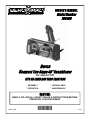
Berco
Compact Two Stage 40" Snowblower
for electric lift
FITS ON LAWN AND YARD TRACTORS
CAUTION:
READ & FOLLOW ALL SAFETY RULES & INSTRUCTIONS BEFORE
OPERATING YOUR EQUIPMENT
104814_EN K-12
* ASSEMBLY * REPAIR PARTS
* OPERATION * MAINTENANCE
*104814_EN*
OWNER’S MANUAL
Model Number
700465

2
LIMITED WARRANTY
Bercomac Limitée
92, Fortin North, Adstock, Quebec, Canada, G0N 1S0
Conditions and Products Covered:
BERCOMAC guarantees any part of the product or accessory
manufactured by BERCOMAC and found in the reasonable
judgment of BERCOMAC to be defective in material and or
workmanship will be repaired or replaced by an authorized
dealer without charge up to our maximum labor rates and pre-
established times. For replacement parts only standard ground
freight services are covered. This warranty extends to the
original retail purchaser only and is not transferable to any
subsequent purchasers.
Warranty Period
(from date of the original retail purchase)
xResidential use: 1 year
xSemi-commercial, professional or rental use: 90 days
Exceptions Noted Below; the following items are guaranteed
by the original manufacturer and have their own warranty,
conditions and limited time:
xTire Chains: 90 days
xEngines: Will vary as per the manufacturer
Please refer to the engine manufacturer’s warranty
statement included with the unit. BERCOMAC is not
authorized to handle warranty adjustments on engines.
Items and Conditions NOT Covered:
This warranty does not cover the following:
xPick-up or delivery charges or in-home services fees.
xAny damage or deterioration of the unit, parts and or finish
of these due to normal use, wear and tear, or exposure.
xCost of regular use or maintenance service or parts, such as
gas, oil, lubricants, tune-up parts, and adjustments.
xAny part or accessory which has been altered, modified,
misused, neglected, accidentally damaged or not properly
installed, maintained, stored or repaired not in accordance
with the instructions in the owner’s manual.
xRepair due to normal wear and or any wear items such as
shear pins, bolts, belts, etc.
xExpedited freight fee services for replacement parts.
xShear bolts and shear pins are to be considered as a
preventive measure not as an assured protection, any
damages resulting from the lack of shear bolts breakage are
not covered.
NOTE: All warranty work must be performed by an authorized
dealer using original (manufacturer) replacement parts.
Owner’s Responsibilities:
BERCOMAC’s defective equipment or part must be returned
to an authorized dealer within the warranty period for repairs.
In the event that defective merchandise must be returned to
manufacturer for repairs, freight fees are prepaid and a written
authorization from BERCOMAC must be obtained by dealer
prior to the shipment. This warranty extends only to
equipment operated under normal conditions. To validate a
warranty claim, it is the user’s responsibility to maintain and
service the unit as specified in the owner’s manual or to have
the unit serviced at their dealer at their expense.
General Conditions:
The sole liability of BERCOMAC with respect to this warranty
shall be strictly and exclusively repair and replacement as
mentioned herein. BERCOMAC shall not have any liability for
any other costs, loss or damage, including but not limited to,
any incidental or consequential loss or damage.
In particular, without being limited to, BERCOMAC shall have
no liability or responsibility for:
xTravel time, overtime, after hours time or other
extraordinary repair charges or relating to repairs and or
replacements outside of normal business hours.
xRental of like or similar replacement equipment during the
period of any, repair or replacement work.
xAny communicating or travel charges.
xLoss or damage to person or property other than that
covered by the terms of this warranty.
xAny claims for lost revenue, lost profit or any similar costs
as a result of damage or repair.
xAttorney’s fees.
BERCOMAC’s responsibility in respect to claims is limited to
making the required repairs or replacement without charge up
to our maximum labor rates and pre-established times and no
claim of breach of warranty shall be cause for cancellation or
rescission of the contract of sale of any product or accessory.
This warranty gives you specific legal rights. You may also
have other rights, which vary from state to state.
NOTE: Bercomac reserves the right to change or improve the design of any part or accessory without assuming any obligation to modify
any product previously manufactured.
Instructions for Obtaining Warranty Services:
Contact dealer where equipment was purchased or any other BERCO service dealer to arrange service at their dealership. To locate a
dealer convenient to you, access our website at www.bercomac.com. Don't forget to bring your proof of purchase (sales receipt) to the
BERCOMAC dealer.

1
TABLE OF CONTENTS
INTRODUCTION .................................................................................................................................................... 2
SAFETY PRECAUTIONS ...................................................................................................................................... 3
SAFETY DECALS .................................................................................................................................................. 5
ASSEMBLY
Tools Required .......................................................................................................................................... 6
Step 1: Snowblower Preparation ............................................................................................................. 6
Step 2: Snowblower Installation ............................................................................................................... 8
OPERATION
Snowblower Operation ............................................................................................................................. 10
Controls ..................................................................................................................................................... 10
MAINTENANCE
Adjustments .............................................................................................................................................. 11
Lubrication ................................................................................................................................................. 11
Cutting Edge Maintenance ....................................................................................................................... 11
Clearing a Clogged Discharge Chute ...................................................................................................... 11
Shear Bolt & Shear Pin Replacement ..................................................................................................... 11
Belt Installation, Adjustment and Replacement ....................................................................................... 12
DISMOUNTING & STORAGE
Snowblower Dismounting ......................................................................................................................... 13
Storage ...................................................................................................................................................... 13
TROUBLESHOOTING ........................................................................................................................................... 14
TORQUE SPECIFICATION TABLE ...................................................................................................................... 17
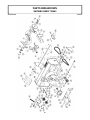
PARTS BREAKDOWN AND PARTS LIST
Chute with rotation system ....................................................................................................................... 18
Snowblower ............................................................................................................................................... 20
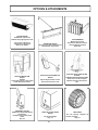
OPTIONS & ATTACHMENTS ............................................................................................................................... 23
PAGE

2
INTRODUCTION
TO THE PURCHASER
This new accessory was carefully designed to give years of dependable service. This manual has been provided to
assist in the safe operation and servicing of your attachment.
NOTE: All photographs and illustrations in the manual may not necessarily depict the actual models or attachment, but
are intended for reference only and are based on the latest product information available at the time of publication.
Familiarize yourself fully with the safety recommendations and operating procedures before putting the machine to
use. Carefully read, understand and follow these recommendations and insist that they be followed by those who will
use this attachment.
THIS SAFETY ALERT SYMBOL IDENTIFIES AN IMPORTANT SAFETY MESSAGE IN THIS
MANUAL THAT HELPS YOU AND OTHERS AVOID PERSONAL INJURY OR EVEN DEATH.
DANGER, WARNING, AND CAUTION ARE SIGNAL WORDS USED TO IDENTIFY THE LEVEL OF
HAZARD. HOWEVER, REGARDLESS OF THE HAZARD, BE EXTREMELY CAREFUL.
DANGER: Signals an extreme hazard that will cause serious injury or death if recommended precautions
are not followed.
WARNING: Signals a hazard that may cause serious injury or death if the recommended precautions are
not followed.
CAUTION: Signals a hazard that may cause minor or moderate injury if the recommended precautions are
not followed.
Record your attachment serial number and purchase date in the section reserved below (there is no serial number on
the subframe). Your dealer requires this information to give you prompt, efficient service when ordering replacement
parts. Use only genuine parts when replacements are required.
If warranty repairs are required please present this registration booklet and original sales invoice to your selling dealer
for warranty service.
This manual should be kept for future reference.
Please check if you have received all the parts for your kit with the list of the
bag and the list of the box.
SERIAL NUMBER : ___________________________
(IF APPLICABLE)
MODEL NUMBER: ___________________________
PURCHASE DATE : ___________________________

3
SAFETY PRECAUTIONS
Careful operation is your best insurance against an accident. Read this section carefully before operating the vehicle
and accessory. This accessory is capable of amputating hands and feet and throwing objects. Failure to observe the
following safety instructions could result in serious injury. All operators, no matter how experienced they may be,
should read this and other manuals related to the vehicle and accessory before operating. It is the owner's legal
obligation to instruct all operators in safe operation of the accessory.
GLOSSARY:
In this manual, right and left sides are determined by
sitting on the seat of the vehicle facing forward.
In this manual, "accessories" means attachments
(snowblower, rotary broom, blade etc.) that you install
on the vehicle (lawn tractors, A.T.V. s etc).
TRAINING:
This symbol, "Safety Alert Symbol", is used
throughout this manual and on the
accessory’s safety labels to warn of the
possibility of serious injury. Please take
special care in reading and understanding
the safety precautions before operating the
vehicle and accessory.
1. Read this owner's manual carefully. Be thoroughly
familiar with the controls and proper use of the
vehicle and accessory. Know how to stop the unit
and disengage the controls quickly.
2. Never allow children to operate the vehicle nor the
accessory. Never allow adults to operate the vehicle
nor the accessory without proper instructions.
3. No one should operate the vehicle nor the
accessory while intoxicated or while taking
medication that impairs the senses or reactions.
4. Keep the area of operation clear of all people,
particularly small children and pets.
PREPARATION:
1. Thoroughly inspect the area where the accessory
is to be used and remove door mats, all foreign
objects and the like.
2. For motorized accessories, disengage all clutches
and shift into neutral before starting engine.
3. Do not operate the accessory without wearing
adequate winter outer garments. Avoid loose fitting
clothing that can get caught in moving parts. Wear
footwear that will improve footing on slippery
surfaces.
4. Handle fuel with care, it is highly flammable.
a) Use approved fuel container.
b) Never add fuel to a running engine or hot engine.
c) Fill fuel tank outdoors with extreme care. Never fill
fuel tank indoors.
d) Never fill containers inside a vehicle, or on a
truck or a trailer bed with a plastic liner. Always
place containers on the ground, away from your
vehicle, before filling.
e) When practical, remove gas-powered
equipment from the truck or trailer and refuel it
on the ground. If this is not possible, then refuel
such equipment on a trailer with a portable
container, rather than from a gasoline
dispenser nozzle.
f) Keep the nozzle in contact with the rim of the
fuel tank or container opening at all times, until
refueling is complete. Do not use a nozzle lock-
open device.
g) Replace fuel cap securely and wipe up spilled
fuel.
h) If fuel is spilled on clothing, change clothing
immediately.
5. Never attempt to make any adjustments while the
engine (motor) is running (except when specifically
recommended by manufacturer).
6. Let the vehicle and accessory adjust to outdoor
temperatures before using.
7. Never use an accessory without proper guards,
plates, or other safety protective devices in place
8. Always make sure to wear the appropriate safety
equipment required (glasses, muffs, mask…) for
each type of product. See operation section.
9. Always make sure of having safe traction on the
vehicle by using the recommended accessories
(chains, A.T.V. tracks, counterweights…). See
operation section.
10. Always make sure the all components are correctly
installed. (driveline securely attached and locked at
both ends, belts properly installed…)
11. Never modif
y
the accessor
y
or an
y
part without
the written consent from the manufacturer.

4
OPERATION:
1. Do not put hands or feet near, under or inside rotating
parts.
2. Exercise extreme caution when operating on or
crossing gravel drives, walks or roads. Stay alert for
hidden hazards or traffic. Do not carry passengers.
3. After striking a foreign object, stop the engine (motor),
disconnect the wire from the spark plug(s) and keep
wire away to prevent accidental starting. Thoroughly
inspect the accessory for any damage and repair
damage before restarting and using the accessory.
4. If the unit should start to vibrate abnormally, stop the
engine (motor) and check immediately for the
cause. Vibration is generally a warning of trouble.
5. Take all possible precautions when leaving the
vehicle unattended. Disengage the power take-off,
lower the attachment, place the transmission into
neutral, set the parking brake, stop the engine and
remove the contact key.
6. Do not run the engine indoors, except when starting
the engine and for transporting in or out of the
building. Do not operate or let motor run in a storage
area without ventilation because gas contains
carbon monoxide which is odorless, colorless and
can cause death.
7. Never use the accessories across the face of
slopes, go from top to bottom. Exercise extreme
caution when using equipment on slopes. Do not
attempt to clear a steep slope.
8. Never tolerate bystanders in the working zone.
Never use an accessory in the direction of
bystanders, it might throw gravel or debris that can
hurt people or damage property.
9. Never operate the accessory at high transport
speeds on slippery surfaces. Use care when
backing up.
10. Do not carry passengers.
11. Disengage power to the accessory when it is
transported or not in use.
12. Never operate the accessory without good visibility
or light.
13. Keep the accessory away from heat sources or
flames.
MAINTENANCE AND STORAGE
1. When cleaning, repairing or inspecting the vehicle
and accessory, make certain that all moving parts
have stopped. For gasoline engine, disconnect wire
from the spark plug(s) and keep wire away to
prevent accidental starting.
2. Check all the bolts and components at frequent
intervals to make sure that they are properly
tightened.
3. Never store a motorized accessory with fuel in the
fuel tank inside a building where ignition sources are
present such as hot water and space heaters,
clothes dryers, and the like. Allow the engine to cool
before storing in any enclosure.
4. Always refer to the owner’s manual when you store
the accessory and vehicle for a prolonged or an
unspecified length of time.
5. Maintain or replace safety and instruction labels, as
necessary.
6 For winter accessories, (if applicable), let the engine
run for a few minutes after clean snow in order to
prevent the rotary parts from freezing.
7. Inspect the vehicle’s and accessory’s air filter (if
applicable) every day. Clean it or replace it as
necessary. Change the oil more often when working
in dusty conditions. See the vehicle’s and
accessory's owner’s manual.
THIS SYMBOL MEANS
DANGER !
BECOME ALERT !
YOUR SAFETY IS INVOLVED !
SAFETY PRECAUTIONS

5
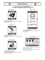
REPLACE IF DECALS ARE DAMAGED
SEE PARTS BREAKDOWN FOR DECAL LOCATION
SAFETY DECALS
DECAL #105131
To avoid serious injury:
Keep hands, feet & clothing away from rotating auger
while engine is running.
DECAL #105130
To avoid serious injury:
Keep hands out of this discharge chute while engine
is running.
To avoid injury from drive belt:
Keep hands, feet & clothing away.
Do not attempt to install or remove drive belt without
reading owner’s manual.
DECAL #105126
DECAL #105128
DECAL #105127
Before installing or using:
Locate, read and make sure to understand all of the
owner’s manual.
Refer to owner’s manual about wearing safety
glasses, ear muffs and mask.
Refer to owner’s manual for use of counter weights,
cat tracks and tire chains.

6
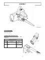
ASSEMBLY
Overall view
TOOLS REQUIRED:
No tools are required.
SNOWBLOWER PREPARATION:
Refer to parts breakdown section for parts
identification.
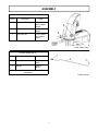
Install the chute (item 2).
Item # Description Action
1 Rotation ring Install over
opening.
2 Chute Place as shown,
turn to lock into
place.
Install chute

7
ASSEMBLY
Install rotation worm (item 2).
Item # Description Action
1 Flat washer 7/16’’, (2) Install on each
side of rotation
support.
2 Rotation worm Install in rotation
support.
3 2.5mm hair pin Secure rotation
worm shaft in
support.
Install rotation worm
Prepare handle
Prepare handle (item 3).
Item # Description Action
1 Hand grip Install on
handle.
2 Hair pin Install on
handle.
Store these parts safely until you install the
snowblower.

8
INSTALLATION
STEP 2
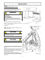
SNOWBLOWER INSTALLATION:
You must install the subframe and drive mechanism
before continuing to install the snowblower.
WARNING
TO PREVENT INJURIES:
Stop the motor.
Apply parking brake.
Remove the ignition key.
Disconnect the wire from the spark plug(s) and
keep away from spark plug(s) to prevent accidental
starting.
Attach the snowblower to the subframe as shown.
Make sure the snowblower is pushed in until locked
into place by the lock (item 1).
Install belts.
NOTE: See the belt installation instructions in the
Maintenance section.
CAUTION
The belt tension arm & needs to be held firmly while
displacing to prevent injury.
CAUTION
Never use the snowblower without the belt guard.
Insert the snowblower in the lock.
Install the cable
After installing the belt, hook the winch cable (item 1)
to the hook (item 2) and secure with a 2.5mm hair pin
(item 3).
Familiarize yourself with the winch control and make
sure the cable stays wrapped from the bottom of the
drum of the winch. See picture of the winch in the
subframe’s owner manual.
Lift and lower the snowblower using the switch.
When lowering the accessory, release the switch of
the winch control as soon as the accessory touches
the ground.

9
INSTALLATION
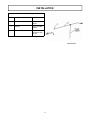
Install handle (item 2).
Item # Description Action
1 Hair pin Remove from
handle.
2 Handle Insert in handle
support.
3 Rotation worm Insert in handle
and secure with
hair pin.
Install handle

10
OPERATION
SNOWBLOWER OPERATION
a) Make sure the snowblower is clear of snow
before engaging the snowblower.
b) Make sure that the auger and impeller operate
freely.
c) Start the tractor engine.
d) Before engaging the snowblower drive, always
have the engine running at medium R.P.M.
e) When removing snow, do not use the snowblower
as a dozer blade to push snow. Allow snowblower
to ingest snow at its own speed. If the speed of
your tractor is too fast, the snowblower may
become overloaded and plug.
IMPORTANT: USE FULL ENGINE R.P.M. WHEN
REMOVING WET OR STICKY SNOW. LOW R.P.M.
WILL TEND TO PLUG THE CHUTE.
WARNING
Hand contact with the rotating impeller inside the
discharge chute is the most common cause of
injury associated with snowblowers. Never use
your hand to clean out the discharge chute.
-Do not attempt to clear plugged chute, auger or
fan of snow while the snowblower's engine is
running.
-Disengage snowblower.
-Lower snowblower to the ground and set
parking brake.
-SHUT THE ENGINE OFF & REMOVE KEY!
-Wait 10 seconds to be sure that all moving parts
such as the impeller blades have stopped
moving.
-Disconnect wire from the spark plug(s) and keep
wire away to prevent accidental starting.
-Do not use hand to unplug chute use a clean-out
tool of at least 36” (1 m) length.
WARNING
Read the tractor Owner’s Manual carefully. Be
thoroughly familiar with the controls & proper
use of the attachment. Know how to stop the
attachment quickly.
CONTROLS
CHUTE ROTATION
The chute rotation handle is located to the left of
steering wheel. Turning the handle in a clockwise
direction, the discharge chute will turn in a clockwise
direction or vice versa.
CHUTE DEFLECTOR
Set the angle of the deflector according to the distance
the snow must be thrown. To change the deflector
angle, loosen the two deflector knobs & adjust the
deflector to the appropriate angle.
WARNING
TO PREVENT INJURIES AND FOR MORE
TRACTION WHEN USING AN ATTACHMENT:
-Rear counterweight of 100 lbs. minimum is
required to counterbalance the attachment’s
weight.
-Manufacturer approved tire chains are required.
-Do not operate on a slope greater than 10°.
-When dismounting the attachment remove rear
counterweights.
-Ear muffs and safety glasses are recommended.

11
MAINTENANCE
Refer to parts breakdown section for parts
identification.
WARNING
TO PREVENT INJURIES:
Stop the motor.
Apply parking brake.
Remove the ignition key.
Disconnect the wire from the spark plug(s) and
keep away from spark plug(s) to prevent accidental
starting.
CAUTION
TO PREVENT INJURIES:
-Check mounting bolts at frequent intervals for
proper tightness in order to prevent costly repairs.
-Make sure your snowblower is in safe working
condition.
-Provide adequate blocking before working under
snowblower when in raised position.
ADJUSTMENTS
SKID SHOE ADJUSTMENT:
LEVEL PAVED SURFACE: Adjust skid shoes to allow
3/16" to 1/4" or 5mm to 7mm clearance (A) between
cutting edge and surface.
UNEVEN OR GRAVEL SURFACE: Adjust skid shoes
to allow 1/2" to 5/8" or 13mm to 16mm clearance (A)
between cutting edge and surface.
CHAIN ADJUSTMENT:
Auger drive chain: Set chain tension leaving 1/2"
deflection in chain span. Retighten hex bolt securely.
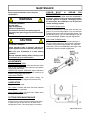
SHEAR BOLT & SHEAR PIN
REPLACEMENT
Shear bolts and shear pins are to be considered a
preventive measure and not an assured protection.
Operator vigilance is required. Thoroughly inspect
the areas where the snowblower is to be used and
remove all foreign objects.
Fan Shear Bolt Replacement:
The fan is protected by a special shear bolt with two
grooves. If you hit a foreign object or ice, the shear bolt
is designed to break in two upon absorbing impact. The
fan will stop turning. This is to avoid damage to the fan
or to the snowblower. Replace only with original parts.
Auger Shear Pin Replacement:
The auger is protected by a special nylon shear pin. If
you hit a foreign object or ice, the shear pin is designed
to break in two upon absorbing impact. The auger will
stop turning. This is to avoid damage to the auger or the
snowblower. Replace only with original parts.
LUBRICATION
Apply oil at all pivot points.
Drive Chains: Lubricate with chain saw chain lubricant
every eight hours of operation.
Chute Rotation System: Oil chute base, rotation worm
every eight hours of operation.
CUTTING EDGE MAINTENANCE
Verify from time to time the wear on the cutting edge
to make sure you do not wear out the base of the
snowblower’s frame. This cutting edge is reversible.
Adjust skid shoes

12
MAINTENANCE
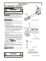
BELT INSTALLATION, ADJUSTMENT,
AND REPLACEMENT:
WARNING
The belt tension arm is spring loaded & needs to be
held firmly while displacing to prevent injury.
SNOWBLOWER BELT:
a) Lower the snowblower to the ground.
b) Remove the belt guard.
c) Remove tension on the belt by lowering the
tension arm (item 1)
d) Loosen the knob (item 2) on the bracket that holds
the bearing (item 3).
e) Install the belt as shown.
f)) Adjust the bracket by pushing on the bearing (item
3) to apply a slight pressure on the back of the belt
(just enough to hold the belt in place). It is normal
that the bearing is off centre (towards the vehicle)
on the pulley. Just make sure that it does not
come into contact with the wall of the pulley.
g) Tighten firmly with the knob.
h) Apply tension on the belt by pulling up the tension
arm (item 1).
i) Engage the snowblower for a few seconds under
supervision. Stop the engine. Inspect the belt to
make sure it does not interfere with any parts; that
it is well inserted in the pulleys and that it has not
flipped on it’s side while still on the pulleys. The V
of the belt must be in the V of the pulleys. The
back of the belt must rest on the flat pulleys (D)
as shown.
j) Reinstall the belt guard.
k) Use genuine belts only, they are specifically
fabricated for this application.
NOTE: There must be a good tension on the belt at
all times. If spring is damaged or stretched, you must
replace it.
DRIVE MECHANISM BELT:
See subframe manual for belt replacement
instructions.
IMPORTANT:
When aligning or replacing the snowblower pulley
(item 4), you must clean the parts and use ‘’Lock-tite’’
2760 on the key and the set screws. Tighten firmly.
Position of the belts
Top view
Position of the bearing
Distance between coils
Belt Insertion
CAUTION
Never use the snowblower without the belt guard.

13
STORAGE
a) Clean snowblower thoroughly and repaint all
parts from which paint has worn.
b) List the replacement parts that will be needed to
be replaced before the next season.
c) Follow the instructions in the Lubrication section.
d) Store the snowblower in a dry place.
WARNING
Never use the snowblower without the belt guard.
SNOWBLOWER DISMOUNTING
a) Remove the hair pin and the handle from the chute
rotation.
b) Remove the belt guard.
c) Unhook the winch cable from the snowblower.
d) Release the tension on the belt by displacing the
tension arm backwards. Remove the belt from the
engine pulley under the tractor.
e) Remove the snowblower by activating the latch of
the female hitch.
f) Reinstall the belt guard.
CAUTION
The belt tension is spring loaded & needs to be
held firmly while displacing to prevent injury.
DISMOUNTING & STORAGE

14
* Please refer to parts breakdown section for parts identification.
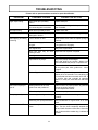
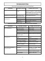
TROUBLESHOOTING
PROBLEM POSSIBLE CAUSES CORRECTIVE ACTION
Auger stops turning. Nylon shear pin is probably
broken.
Replace shear pin.
The reduction chain is broken or
the connecting link is unlocked.
Remove both chain guards. Inspect & repair
chain if needed.
Fan stops turning. Shear bolt is probably broken. Replace shear bolt.
Snowblower stops turning. One of the two belts is probably
damaged or broken.
Check both belts and replace damaged belt(s).
Belt snapping, shredding
or burning
Lack of tension on belt. Adjust manual clutch cable or replace springs if
stretched.
Snowblower engaged when
plugged.
Make sure the auger & the fan are not frozen
or plugged before engaging.
Not original belts. Always use original belts.
Worn belt. Belt may be worn
causing a slack.
Inspect the belt. Replace if required.
Not original shear bolts. Use original shear bolts
Imperfections in pulleys. Verify if the pulleys are damaged.
Verify that pulleys are smooth, without rust
spots. Sand down the pulleys or replace them.
Interference. Make sure that belt does not come into contact
with any other part, bolts, guides etc... when
engaged.
Belt has flipped on its side. When installing new belt, have snowblower run
between 20 to 40 seconds. Turn everything off
and verify that belt has not turned on its side. If
so, remove belt and re-install in opposite
fashion to rectify the bad twist the belt has
taken.
Belt comes off pulley or
flips off
Bearing which acts as a belt
guide is not well positioned.
Guides must be in proper position to guide the
belt into the pulleys properly.
See belt adjustment section.
Defective pulley. Replace the pulley
Chute plugs easily. Tractor engine turning too slowly. Run engine at full throttle during snowblowing
operation.
Advancing too quickly with tractor. Allow snowblower to ingest snow at its own
speed.
Chute rotation is difficult. Dirt or ice may be underneath
chute.
Dismount chute by removing the rotation
worm. Turn the chute completely towards the
rear and it will disconnect from base. Clean the
base of chute and the rotation ring. Lubricate &
re-install.

15
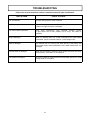
TROUBLESHOOTING
PROBLEM POSSIBLE CAUSES CORRECTIVE ACTION
Snowblower digs into ground. Ground is not frozen or
too soft.
Adjust skid shoes lower so they may better
support the snowblower. If problem persists,
change skid shoes for heavy duty skid shoes
(option #700243) which cover more surface
and prevents snowblower from digging.
Snowblower does not raise evenly. Tire pressure uneven
from one side to another.
Verify and adjust tire pressure:
Snowblower vibrates or is Damaged pulley. Replace pulley.
abnormally noisy. Damaged bearing. Replace bearing.
Damaged fan. Dismount & repair or replace fan.
Damaged auger. Replace auger.
* Please refer to parts breakdown section for parts identification.
* Please refer to parts breakdown section in subframe manual for parts identification.
PROBLEM POSSIBLE CAUSES CORRECTIVE ACTION
Winch runs backwards. Winch wires reversed. Recheck wiring.
Switch wires reversed. Recheck wiring.
Switch installed incorrectly. Check switch installation.
Battery wires reversed. Recheck wiring.
Winch cable is not winded up from
the bottom of spool.
Wind winch cable from underneath.
Winch will not operate or runs in
one direction only.
Vehicle’s ignition switch is at OFF
position.
Turn vehicle’s ignition switch at ON
position.
Broken wires or bad connection. Check for poor connections.
Control switch is inoperative. Replace control switch.
Relay or breaker is damaged. Replace the relay or breaker.
Limit switch is damaged. Replace limit switch.
Winch is damaged. Replace or repair winch.
Winch runs but with insufficient
power or line speed.
Weak battery. Recharge or replace battery.
Check charging system
Poor battery connection. Check battery terminals for
corrosion. Clean when required.
Winch is damaged. Replace or repair winch.

16
MAINTENANCE
* Please refer to parts breakdown section in subframe manual for parts identification.
TROUBLESHOOTING
HOW TO KNOW POINTS TO CHECK
Poor connections. Recheck wiring with the owner's manual.
HI/LOW voltage tester does not work. Connect it on battery posts (+ and -) of a functional battery.
If there is no light, the tester is damaged.
The control switch inoperative. Test both connectors with HI/LOW voltage tester.
If light comes ON in both positions (IN & OUT), the switch is
operative.
Relay is damaged When it is working, there is a "CLICK" sound when the control switch
is activated. Check connections with HI / LOW voltage tester.
Winch is damaged The ultimate test is to connect the winch directly to the battery and
reverse the wires to test both directions. If the winch doesn't work, it is
damaged.
The limit switch is damaged. When the limit switch is pushed or stuck inside, the winch can't raise
the accessory, only lower it. If not replace it.
The breaker is damaged. Check the voltage on both terminals on the breaker with the HI / LOW
voltage tester. If not replace.

17
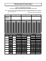
TORQUE SPECIFICATION TABLE
GENERAL TORQUE SPECIFICATION TABLE
USE THE FOLLOWING TORQUES WHEN SPECIAL TORQUES ARE NOT GIVEN
NOTE: These values apply to fasteners as received from supplier, dry or when lubricated with normal oil. They do not
apply if special graphited or moly disulphide greases or other extreme pressure lubricants are used. This applies to
both UNF and UNC threads.
* Thick nuts must be used with grade 8 bolts
SEE G rade No.
2 5 8 *
BOLT HEAD
IDENTIFICATION
MARKS AS PER GRADE
NOTE MANUFACTURING
MARKS W ILL VARY
TORQUE TORQUE TORQUE
BOLT SIZE FOOT POUNDS NEW TON-METERS FOOT POUNDS NEW TON-METERS FOOT POUNDS NEW TON-METERS
Inches Millimetre Min. Max. Min. Max. Min. Max. Min. Max. Min. Max. Max. Min. Max. Max.
1/4" 6.35 5 6 6.8 8.13 911 12.2 14.9 12 15 16.3 30.3
5/16" 7.94 10 12 13.6 16.3 17 20.5 23.1 27.8 24 29 32.5 39.3
3/8" 9.53 20 23 27.1 31.2 35 42 47.5 57 45 54 61 73.2
7/16" 11.11 30 35 40.7 47.4 54 64 73.2 86.8 70 84 94.9 113.9
1/2" 12.7 45 52 61 70.5 80 96 108.5 130.2 110 132 149.2 179
9/16" 14.29 65 75 88.1 101.6 110 132 149.2 179 160 192 217 260.4
5/8" 15.88 95 105 128.7 142.3 150 180 203.4 244.1 220 264 298.3 358
3/4" 19.05 150 185 203.3 250.7 270 324 366.1 439.3 380 456 515.3 618.3
7/8" 22.23 160 200 216.8 271 400 480 542.4 650.9 600 720 813.6 976.3
1" 25.4 250 300 338.8 406.5 580 696 786.5 943.8 900 1080 1220.4 1464.5
METRIC BOLT TORQUE SPECIFICATIONS
COARSE THREAD
Size Screw Grade No. Pitch
(mm)
Foot Pounds Newton-Meters Pitch
(mm)
Foot P ounds Newton-Meters
M6 4T 1.00 3.6 - 5.8 4.9 - 7.9 - - -
7T 5.8 - 9.4 7.9 - 12.7 - -
8T 7.2 - 10 9.8 - 13.6 - -
M8 4T 1.25 7.2 - 14 9.8 - 19 1.00 12 - 17 16.3 - 23
7T 17 - 22 23 - 29.8 19 - 27 25.7 - 36.6
8T 20 - 26 27.1 - 35.2 22 - 31 29.8 - 42
M10 4T 1.50 20 - 25 27.1 - 33.9 1.25 20 - 29 27.1 - 39.3
7T 34 - 40 46.1 - 54.2 35 - 47 47.4 - 63.7
8T 38 - 46 51.5 - 62.3 40 - 52 54.2 - 70.5
M12 4T 1.75 28 - 34 37.9 - 46.1 1.25 31 - 41 42 - 55.6
7T 51 - 59 69.1 - 79.9 56 - 68 75.9 - 92.1
8T 57 - 66 77.2 - 89.4 62 - 75 84 - 101.6
M14 4T 2.00 49 - 56 66.4 - 75.9 1.50 52 - 64 70.5 - 86.7
7T 81 - 93 109.8 - 126 90 - 106 122 - 143.6
8T 96 - 109 130.1 - 147.7 107 - 124 145 - 168
M16 4T 2.00 67 - 77 90.8 - 104.3 1.50 69 - 83 93.5 - 112.5
7T 116 - 130 157.2 - 176.2 120 - 138 162.6 - 187
8T 129 - 145 174.8 - 196.5 140 - 158 189.7 - 214.1
M18 4T 2.00 88 - 100 119.2 - 136 1.50 100 - 117 136 - 158.5
7T 150 - 168 203.3 - 227.6 177 - 199 239.8 - 269.6
8T 175 - 194 237.1 - 262.9 202 - 231 273.7 - 313
M20 4T 2.50 108 - 130 146.3 - 176.2 1.50 132 - 150 178.9 - 203.3
7T 186 - 205 252 - 277.8 206 - 242 279.1 - 327.9
8T 213 - 249 288.6 - 337.4 246 - 289 333.3 - 391.6
FINE THREAD

18
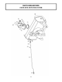
PARTS BREAKDOWN
CHUTE WITH ROTATION SYSTEM
La page est en cours de chargement...
La page est en cours de chargement...
La page est en cours de chargement...
La page est en cours de chargement...
La page est en cours de chargement...
La page est en cours de chargement...
La page est en cours de chargement...
La page est en cours de chargement...
-
 1
1
-
 2
2
-
 3
3
-
 4
4
-
 5
5
-
 6
6
-
 7
7
-
 8
8
-
 9
9
-
 10
10
-
 11
11
-
 12
12
-
 13
13
-
 14
14
-
 15
15
-
 16
16
-
 17
17
-
 18
18
-
 19
19
-
 20
20
-
 21
21
-
 22
22
-
 23
23
-
 24
24
-
 25
25
-
 26
26
-
 27
27
-
 28
28


Bercomac 700465 Manuel utilisateur
- Catégorie
- Souffleuses à neige
- Taper
- Manuel utilisateur
dans d''autres langues
- English: Bercomac 700465 User manual
Documents connexes
-
Bercomac 700478-3 Manuel utilisateur
-
-
-
-
-
-
-
-
-