Ideal 400A AC/DC TRMS TightSight® Clamp Meter Manuel utilisateur
- Catégorie
- Multimètres
- Taper
- Manuel utilisateur
Ce manuel convient également à

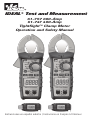
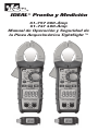
61-757 600-Amp
61-747 400-Amp
TightSight™ Clamp Meter
Operation and Safety Manual
IDEAL® Test and Measurement
Instrucciones en español adentro / Instrucions en français à l’intérieur

Table of Contents
2
Introduction ......................................................................3
Contacting IDEAL INDUSTRIES, INC ..........................................3
Safety Information ...............................................................4
Warnings ................................................................................................... 4-5
Cautions ........................................................................................................ 5
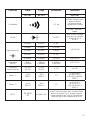
Symbols .................................................................................................... 6-7
Operation ..................................................................8-23
Identification and description of operating controls and functions ............ 8-9
Operating Features ............................................................................... 10-11
Using Test Leads ........................................................................................12
Meter Operation ................................................................................... 13-17
Non-Contact Voltage Testing...........................................................13
Measuring Current .......................................................................... 14
Measuring Voltage ..........................................................................14
Measuring Continuity .....................................................................15
Measuring Resistance ..................................................................... 15
Measuring Capacitance ...................................................................16
Measuring Diodes ...........................................................................16
Measuring Frequency .....................................................................17
Measuring Temperature ..................................................................17
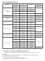
Functions Operation Table .................................................................... 18-19
Functions Indication Table .................................................................... 20-21
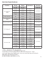
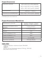
Electrical Specifications ........................................................................ 22-23
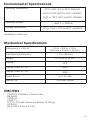
Environmental Specifications ................................................ 24
Mechanical Specifications ................................................... 24
EMC / EMI ....................................................................... 24
FCC ............................................................................... 25
Safety ............................................................................ 25
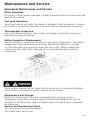
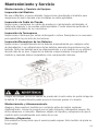
Maintenance and Service ................................................ 26-27

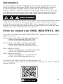
Introduction
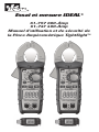
The IDEAL® 61-757 and 61-747 TightSight™ Clamp Meters are auto ranging
true root mean square (TRMS) digital clamp meters that measure AC and DC
current (amps) via the clamp head, measure voltage, frequency, resistance,
continuity, capacitance, diode via test-leads and measure temperature via a
K-Type thermocouple, and detects the presence of voltage between 40V to 600V
via a non-contact sensor in the right tip of the clamp.
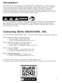
Contacting IDEAL INDUSTRIES, INC.
To contact IDEAL INDUSTRIES, INC., call one of the following telephone numbers:
IDEAL Industries USA Customer Service
• Phone Number: 800-435-0705
• Email: [email protected]
IDEAL Industries Canada Customer Service
• Phone Number: 905-683-3400
• Email: [email protected]
IDEAL Industries EMEA
• Phone Number: +44 (0)1925 444 446
• Email: eur[email protected]
IDEAL Industries Australia
• Phone Number: +61 3 9562 0175
• Email: [email protected]
Or visit the IDEAL Electrical Website at www.idealind.com
To register your product, find manuals, watch videos, simply scan this QR code.
3
Arc Flash and Shock Hazard, Proper PPE Required. Follow all safety procedures,
wear proper PPE in accordance to NFPA 70E. Read and fully understand the
instruction manual prior to using this product. Failure to comply can result in
serious injury or death.
Introduction ......................................................................3
Contacting IDEAL INDUSTRIES, INC ..........................................3
Safety Information ...............................................................4
Warnings ................................................................................................... 4-5
Cautions ........................................................................................................ 5
Symbols .................................................................................................... 6-7
Operation ..................................................................8-23
Identification and description of operating controls and functions ............ 8-9
Operating Features ............................................................................... 10-11
Using Test Leads ........................................................................................12
Meter Operation ................................................................................... 13-17
Non-Contact Voltage Testing...........................................................13
Measuring Current .......................................................................... 14
Measuring Voltage ..........................................................................14
Measuring Continuity .....................................................................15
Measuring Resistance ..................................................................... 15
Measuring Capacitance ...................................................................16
Measuring Diodes ...........................................................................16
Measuring Frequency .....................................................................17
Measuring Temperature ..................................................................17
Functions Operation Table .................................................................... 18-19
Functions Indication Table .................................................................... 20-21
Electrical Specifications ........................................................................ 22-23
Environmental Specifications ................................................ 24
Mechanical Specifications ................................................... 24
EMC / EMI ....................................................................... 24
FCC ............................................................................... 25
Safety ............................................................................ 25
Maintenance and Service ................................................ 26-27

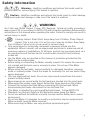
Warning - Identifies conditions and actions that could result in
possible death or serious injury if the hazard is realized.
Caution - Identifies conditions and actions that could result in meter damage,
equipment under test damage or data loss if the hazard is realized.
WARNING
Safety Information
Arc Flash and Shock Hazard, Proper PPE Required. Follow all safety procedures,
wear proper PPE in accordance to NFPA 70E and follow the guidelines below and the
instructions in this manual when operating the meter. Failure to comply can result in
serious injury or death.
• Choking Hazard, Small Parts. Keep Away from Children. Sharp Objects
Hazard, This is not a toy. It is not for use or play by children. Keep Away
from Children. Failure to do so can result in serious injury.
• Only experienced or technically competent consumers should use this
equipment. When in doubt, call an experienced electrician to make any and all
necessary repairs or installations. At all times, perform any necessary work on a
de-energized circuit that has had its circuit breaker turned off and has been
locked out.
• Use the Meter only as specified in this manual or protection provided by the
Meter can be compromised.
• Before using or connecting the Meter, visually inspect it to ensure the cases are
not cracked and the back case is securely in place. Do not use if the Meter
appears damaged.
• Before using the test leads, inspect carefully for damaged insulation, exposed
metal or cracked probes. Check test leads for continuity. Do not use leads if they
appear damaged.
• Use only approved test leads. Do not use improvised connections that could
present a safety hazard.
• Never measure ac current while the test leads are inserted into the input jacks.
• When using the probes, keep fingers behind the finger guards on the probes.
• Connect the common test lead before connecting the live test lead. When
disconnecting test leads, disconnect the live test lead first.
• This Meter is intended for use by qualified electricians. Follow NFPA 70E
• Standards for Electrical Safety in the Workplace when using this Meter.
• Do not use without the batteries correctly in place and the battery door closed
and secured.
• Do not use Meter if it operates incorrectly as protection may be compromised.
When in doubt, have the Meter serviced.
• When servicing the Meter, use only specified replacement parts.
4

Arc Flash and Shock Hazard, Proper PPE Required. Follow all safety procedures,
wear proper PPE in accordance to NFPA 70E and follow the guidelines below and
the instructions in this manual when operating the meter. Failure to comply can
result in serious injury or death.
• Have the Meter serviced only by qualified service personnel.
• Do not use the Meter around explosive gas, dust, or vapor, or during electrical
storms, or in wet environments.
• When measuring, keep fingers behind the Tactile Barrier. See “The Meter” on
pg. 8 and 9.
• Do not apply more than the rated voltage, as marked on the Meter, between the
terminals or between any terminal and earth ground.
• To avoid false readings that can lead to electrical shock and injury, replace the
batteries as soon as the low battery indicator ( ) appears.
• Remove the test leads from the circuit prior to removing the battery door.
• Voltages exceeding 30VAC RMS or 60VDC pose a shock hazard so use caution.
• Always ensure that test leads are secured so that they cannot be accidentally
snagged or tripped over.
• Do not work alone so that assistance can be rendered in an emergency.
Use extreme caution when working around bare conductors or bus bars. Contact
with the conductor could result in electric shock.
• Adhere to local and national safety codes. Individual protective equipment must
be used to prevent shock and arc blast injury where hazardous live conductors
are exposed.
• Disconnect circuit power and discharge all high-voltage capacitors before you
measure resistance, continuity, or capacitance.
• Do not measure current in circuits carrying more than 600 V or 600 A with the
Meter Jaw.
• Never operate the Meter with the back cover removed or the case open.
• Cancer and Reproductive Harm - www.P65Warnings.ca.gov
CAUTION
Meter damage, equipment under test damage or data loss can occur
if the following guidelines are not adhered to.
• Use the proper terminals, function, and range for the measurement application.
• Clean the case and accessories with a damp cloth and mild detergents only. Do
not use abrasives or solvents. Make sure the meter is completely dry before use.
5
WARNING

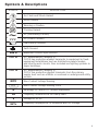
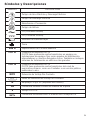
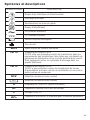
Symbols & Descriptions
SYMBOL DESCRIPTION
Arc Flash and Shock Hazard
Shock Hazard
Warning or Caution
Choking Hazard
AC (Alternating Current)
DC (Direct Current)
Low Battery Indicator
Earth Ground
600 A Maximum Current Specification
CAT III IEC Measurement Category III
CAT III has protection against transients in equipment in fixed-
equipment installations such as distribution panels feeders,
and short branch circuits. Also included are lighting systems in
larger buildings.
CAT IV IEC Measurement Category IV
CAT IV has protection against transients from the primary
supply level such as a Meter or overhead or underground utility
service.
NCV Non-Contact Voltage Sensing
NCV Non-Contact Voltage Sensing Point
AAmperage AC and/or DC (model dependent)
Hz Frequency measured via the clamp head
VVoltage AC or DC
Hz% Frequency displayed as % measured with AC Voltage
6

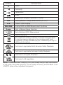
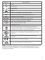
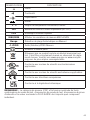
SYMBOL DESCRIPTION
ΩOhms
Continuity
Capacitance
Diode
°F °C Temperature Degrees Fahrenheit / Celsius
LoZ Low Impedance Voltage Measurement (61-757)
LCD Liquid Crystal Display
MAX/MIN Display MAX and MIN Measurement Variations
Range Auto or Manual Range Selection
∆ ZERO Delta (Relative)/ZERO Measurement
Double Insulation
Do not dispose of this product as unsorted municipal waste.
It must be properly disposed of in accordance with local
regulations. Please see www.epa.gov or www.erecycle.org for
additional information.
Conforms to applicable North American Safety Standards
Conforms to applicable Australian Safety Standards
Conforms to European Directives
Conforms to UK Legislation
Symbols & Descriptions
NOTE: The Measurement Category (CAT) and voltage rating of any combination
of test probe, test probe accessory, current clamp accessory, and the Meter is the
LOWEST rating of any individual component.
7

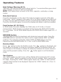
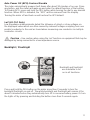
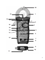
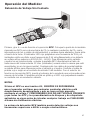
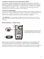
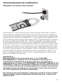
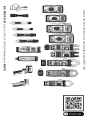
Identification and Description of Operating Controls and Functions for
the 61-757 600A AC/DC, 61-747 400A AC/DC:
1. Tapered Jaws with Hook Tip
2. LoZ (61-757 Only)
3. Data Hold & Peak Hold (Peak Hold 61-757 Only)
4. Function Dial
5. Max/Min
6. Main Display (LCD)
7. Volts and Resistance (V-Ω) Input Terminal
8. COM Input Terminal
9. TightSight® Bottom Display
10. Probe Holder
11. Magnetic Hanging Strap Clip
12. Protective Rubber Overmolding
13. Range Button
14. Relative/Zero Button
15. Select / Backlight / Flashlight Button
16. Lever
17. NCV/Continuity/High Voltage Indicator
18. Tactile Barrier
19. Flashlight
20. NCV Sensing Point
8
Operation

5
1
16 4
7
10
9
11
8
15
14
12
17
3
6
18
19
9
2
6000 Count Display
20
13

High Voltage Warning (HI-V)
The meter LED remains RED and the beep lasts for 1 second and then goes silent
when voltages in excess of 30V are measured.
NOTE: This feature does not work in the Ohm, capacitor, continuity or clamp
modes.
Data Hold Feature
Press the Hold button on the side of the meter to toggle in and out of the data
hold mode. “HOLD” appears in the upper left of the meter display when data hold
is active. Use the data hold feature to lock a measurement reading on the display.
Press the Hold button again to unlock the display and obtain a real-time reading.
Peak Feature (61-757 Only)
In PEAK mode, the meter displays the PEAK value of AC Volts or Current
measurement. PEAK function is enabled by Depressing the PEAK HOLD button
for > 2 seconds. To Exit PEAK Mode Depress the PEAK HOLD button again for > 2
seconds.
MAX/MIN Feature
The MAX/MIN records the maximum and minimum measured value. Press the
MAX/MIN button to activate this feature and to toggle between MAX, and MIN
readings. The unit will continually capture MAX and MIN values over time.
Depressing the MAX/MIN button for >2 sec. exits the MAX/MIN mode.
Relative Mode
Press “ ” button to enter the Relative mode. The “ ” symbol is displayed, and
the value on the display is stored as a reference value. In the Relative mode, the
value shown on the display is always the difference between the stored reference
value and the present reading. Press the “ ” button again to exit the Relative
mode.
Zero Feature
The “ZERO” button is used to zero out the display before measuring DC current.
Press the “ZERO” button to subtract out the non-zero number. Then, measure the
DC amps. Pressing the “ZERO” button again causes the “ZERO” to flash and the
original offset number to be displayed. Depress the “ZERO” button for >2 sec. to
exit this mode.
10
Operating Features

Auto Power Off (APO) Feature Disable
The meter automatically powers itself down after about 30 minutes of no use. Press
any button, and the meter will wake up and enter the default function of that setting.
To Disable APO, press and hold the SEL button while turning the dial to any desired
function. When APO is defeated, the “APO” will be removed from the display.
Turning the meter off and back on will restore the APO default.
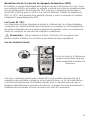
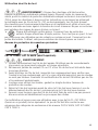
LoZ (61-757 Only)
Low impedance measurements defeat the influence of ghost or stray voltages on
the displayed value which are often caused by induced voltages coupling from one
parallel conductor to the next as found when measuring one conductor in multiple
conductor circuits.
11
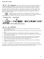
Press and hold the SEL button on the meter more than 2 seconds to turn the
backlight/flashlight on and off. The white backlight and flashlight will remain lit for
about 5 minutes before they automatically turn off to conserve battery power. Or turn
the lights off by pressing and holding the button more than 2 seconds again.
Backlight / Flashlight
Caution - Use caution when using the LoZ function on equipment that may be
damaged by being connected to a low impedance source.
Backlight and flashlight
are selectable to be
on in all functions.

12
Using Test Leads
WARNING: Arc Flash and Shock Hazard, Proper PPE Required.
Follow all safety procedures, wear proper PPE in accordance to NFPA 70E and
follow the guidelines below and the instructions in this manual when operating
the meter with TL-757 Test Leads or equivalent. Test Leads must be rated for the
electrical environment the meter is being used in and have a voltage rating of at
least the voltage of the circuit to be measured. Failure to comply can result in
serious injury or death.
• Choking Hazard, Small Parts. Keep Away from Children. Sharp
Objects Hazard, This is not a toy. It is not for use or play by children.
Keep Away from Children. Failure to do so can result in serious injury.
Protective Cap Guard Ring
CAT III 1000V, CAT IV 600V (with cap on)
WARNING: To prevent possible electrical shock or personal injury, the
protective caps must be in place when operating a properly rated electrical meter/
tester using the TL-757 Test Leads in a CAT IV 600V or CAT III 1000V environment.
WARNING:
1. Use only approved test leads. Do not use improvised connections that could
present a safety hazard.
2. Never measure AC or DC current while the test leads are inserted into the input
jacks.
3. Prior to using the test leads, inspect them carefully for damaged insulation,
exposed metal or bent probes. Check test leads for continuity. Do not use leads
if they appear damaged.
4. When using the probes, keep fingers behind the finger guards on the probes.
5. Connect the common test lead before connecting the live test lead. When
disconnecting test leads, disconnect the live test lead first.
6. Always ensure that test leads are secured so that they cannot be accidentally
snagged or tripped over.
This meter is intended for use with the IDEAL TL-757 lead set (provided with this
product) or equivalent. The lead set must comply with requirements for Overvoltage
and Measurement Categories CAT IV 600V CAT III 1000V CAT II 1000V.

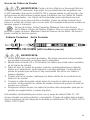
Meter Operation
13
Non-Contact Voltage Sensing
First, rotate the function key to the NCV position. Place the jaw tip marked with
NCV close to an AC outlet (or any AC conductor such as light switches or power
cords) and scan back and forth across the outlet. Red indicator LED flashes at a
frequency of 3Hz, and the buzzer beeps at a frequency of 3Hz simultaneously if live
voltage is greater than 40VAC (50~60Hz) is detected. To differentiate between hot
and neutral in an outlet, place the NCV tab directly next to each slot in the outlet.
The tone (buzzer) will sound over the slot that is energized and not on the neutral
slot. Either test lead can also be used to differentiate between the hot and neutral.
Plug the red or black test lead into the V input jack on the meter. With the function
switch in the NCV position, insert the probe end of just one probe into the slots on
the outlet. The meter will beep and the Red LED will flash when a hot conductor is
contacted.
NOTES:
While the NCV is a helpful function, it is ALWAYS RECOMMENDED
that the operator verify that any electrical conductor is completely de-
energized and that no voltage is present by measuring for voltage AND
CONFIRMING THAT NO VOLTAGE IS PRESENT and that all applicable
PPE and lock out tag out procedures be followed before attempting any
work on ANY electrical distribution system.
Voltages with frequencies higher than 60Hz or electrostatic charges
may also be detected by the NCV sensing antenna.

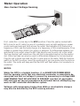
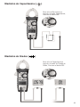
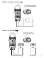
Measuring AC ( ) or DC ( ) Current (Amps)
*Note: When measuring AC voltage, Ghost or stray voltages (caused by
induced voltages coupling from one parallel conductor to the next as found when
measuring one conductor in multiple conductor circuits) may cause an incorrect
value. Selecting the Low impedance position (LoZ) on the dial, (see inset above)
while measuring voltage with the 61-757 will defeat the influence of Ghost or Stray
voltage. 14
Measuring AC ( ) or DC ( ) Voltage
AC V LoZ Setting*
Note:
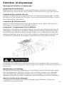
• When measuring current, align conductor with dash marks on clamp jaws.
• For DC current point the arrow (located at base of jaws) towards the load.

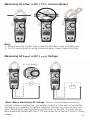
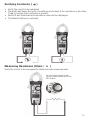
Verifying Continuity ( ) Measuring AC ( ) or DC ( ) Current (Amps)
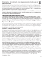
• Verify the circuit is de-energized.
• The meter will sense the level of resistance and a beep if the resistance is less than
10 Ω to confirm that continuity is present.
• Red LED will illuminate and resistance value will be displayed.
• The default setting is continuity.
Verify the circuit is de-energized to obtain accurate measurements.
Measuring Resistance (Ohms / Ω )
15
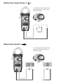
Measuring AC ( ) or DC ( ) Voltage
To exit Continuity and enter
the resistance mode, press the
SEL Button

16
Measuring Capacitance ( )
Measuring Diodes ( )
To exit Resistance and enter
the Capacitance mode, press
the SEL Button
To exit Capacitance and enter
the Diode Test mode, press
the SEL Button

Current must be greater than 6
Amps AC.
17
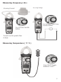
Measuring Frequency ( Hz )
Measuring Temperature ( °F °C )
Hz using Current Hz using Voltage
For % Duty Cycle Press
the SEL button
For Hz Press the SEL
button
Current must be greater than
6 Amps
Press SEL to toggle
between F and C

Button
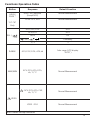
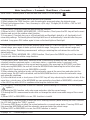
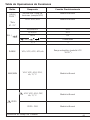
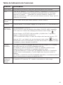
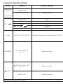
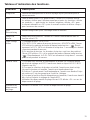
Response Default Function Operation
Note: Long Press: > 2 seconds Short Press: < 2 seconds
HOLD/
PEAK *
*61-757
Only
HOLD: All Functions
(Except NCV)
Normal Measurement Short Press: Circularly enter or exit the data hold mode, LCD will display “ ”
PEAK: ACV, ACA Normal Measurement 1) Long Press: Circularly enter into or exit the PEAK function.
2) After entering the PEAK function, exits the automatic range and enters the highest range.
3) Peak Hold response time < 1ms; Accuracy is ±(5% rdg + 15 digits) @ 45-60Hz; >10V for VAC
and >10A for A AC.
SEL /
ACA / Hz / DCA ACA 1) Short press: Circularly select the appropriate test function.
2) When in HOLD, RANGE, MAX/MIN, REL / ZERO function, Short press the SEL key will exit current
function and go into the relative select function.
3) Long press: Circularly turn on or off the backlight and flashlight, default is off, Applicable to all
measuring settings. The backlight and flashlight will turn off automatically 5 minutes after they are
activated. Long press SEL button again to turn on the backlight and flashlight.
ACV/DCV ACV
Hz/% Hz
/ Ω / / Continuity
°F/°C °F
RANGE
ACV, DCV, DCA, ACA, ΩAuto range (LCD display
“AUTO”)
1) Short press the RANGE key to enter manual range mode (LCD will not display “AUTO”), and the
current range, press again to enter cyclical selection range. Long press: exits manual range and
enters Auto range. Switching measurement setting or restarting the unit returns the unit to the
default setting.
2) In HOLD / PEAK, MAX/MIN, REL / ZERO function, Short press the RANGE key to exit the current
function and enter the relative range function.
MAX/MIN
ACV, DCV, ACA, DCA,
Ω, °F/°C Normal Measurement
1) Short press: enter “MAX/MIN” statistics mode, continuously updates the data, and you can
circularly view the maximum value→ minimum value→ maximum value. Long press: exits
statistical mode and returns to the normal working mode. After pressing the REL/ZERO, and then
short pressing MAX/MIN, the unit will show the MAX/MIN after deducting the initial offset value.
2) When HOLD function is in use, MAX/MIN is invalid.
3) After entering the statistical mode, exit the automatic range at the same time and enter into the
current range, the APO will be disabled; exit the MAX/MIN function to restore the automatic range
and automatic shutdown.
4) In the statistical mode, a short press of the HOLD key will stop refreshing the statistical data. At the
same time, a short press of the MAX/MIN key can review the stored data of MAX/MIN, a short press
of the HOLD key exits HOLD to continue refreshing the statistical data.
/ZERO
: ACV, DCV, ACA, CAP,
Ω, °F/°C Normal Measurement
1) Short press: Circularly enter or exit REL function (when entering REL function, LCD will display
“ ” symbol )
2) Entering the REL function, exits auto range and enters into the current range.
3) Entering the REL measurement mode does not change the actual measurable range of the current
range
4) When HOLD or MAX/MIN is in use, REL function is invalid.
ZERO : DCA Normal Measurement
1) Short press: Circularly enter or exits the ZERO clearing function (when entering the ZERO function,
the LCD will display the “ZERO” symbol)
2) Pressing ZERO does not affect the current automatic or manual range status. Pressing ZERO and
then pressing MAX/MIN will exit the automatic range and enter the current range.
3) When HOLD or MAX/MIN is in use, the ZERO function is invalid.
Non-Contact Voltage Indication
Displays “EF” – Electromagnetic Field
Functions Operation Table
18

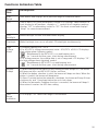
Button
Response Default Function Operation
Note: Long Press: > 2 seconds Short Press: < 2 seconds
HOLD/
PEAK *
*61-757
Only
HOLD: All Functions
(Except NCV)
Normal Measurement Short Press: Circularly enter or exit the data hold mode, LCD will display “ ”
PEAK: ACV, ACA Normal Measurement 1) Long Press: Circularly enter into or exit the PEAK function.
2) After entering the PEAK function, exits the automatic range and enters the highest range.
3) Peak Hold response time < 1ms; Accuracy is ±(5% rdg + 15 digits) @ 45-60Hz; >10V for VAC
and >10A for A AC.
SEL /
ACA / Hz / DCA ACA 1) Short press: Circularly select the appropriate test function.
2) When in HOLD, RANGE, MAX/MIN, REL / ZERO function, Short press the SEL key will exit current
function and go into the relative select function.
3) Long press: Circularly turn on or off the backlight and flashlight, default is off, Applicable to all
measuring settings. The backlight and flashlight will turn off automatically 5 minutes after they are
activated. Long press SEL button again to turn on the backlight and flashlight.
ACV/DCV ACV
Hz/% Hz
/ Ω / / Continuity
°F/°C °F
RANGE
ACV, DCV, DCA, ACA, ΩAuto range (LCD display
“AUTO”)
1) Short press the RANGE key to enter manual range mode (LCD will not display “AUTO”), and the
current range, press again to enter cyclical selection range. Long press: exits manual range and
enters Auto range. Switching measurement setting or restarting the unit returns the unit to the
default setting.
2) In HOLD / PEAK, MAX/MIN, REL / ZERO function, Short press the RANGE key to exit the current
function and enter the relative range function.
MAX/MIN
ACV, DCV, ACA, DCA,
Ω, °F/°C Normal Measurement
1) Short press: enter “MAX/MIN” statistics mode, continuously updates the data, and you can
circularly view the maximum value→ minimum value→ maximum value. Long press: exits
statistical mode and returns to the normal working mode. After pressing the REL/ZERO, and then
short pressing MAX/MIN, the unit will show the MAX/MIN after deducting the initial offset value.
2) When HOLD function is in use, MAX/MIN is invalid.
3) After entering the statistical mode, exit the automatic range at the same time and enter into the
current range, the APO will be disabled; exit the MAX/MIN function to restore the automatic range
and automatic shutdown.
4) In the statistical mode, a short press of the HOLD key will stop refreshing the statistical data. At the
same time, a short press of the MAX/MIN key can review the stored data of MAX/MIN, a short press
of the HOLD key exits HOLD to continue refreshing the statistical data.
/ZERO
: ACV, DCV, ACA, CAP,
Ω, °F/°C Normal Measurement
1) Short press: Circularly enter or exit REL function (when entering REL function, LCD will display
“ ” symbol )
2) Entering the REL function, exits auto range and enters into the current range.
3) Entering the REL measurement mode does not change the actual measurable range of the current
range
4) When HOLD or MAX/MIN is in use, REL function is invalid.
ZERO : DCA Normal Measurement
1) Short press: Circularly enter or exits the ZERO clearing function (when entering the ZERO function,
the LCD will display the “ZERO” symbol)
2) Pressing ZERO does not affect the current automatic or manual range status. Pressing ZERO and
then pressing MAX/MIN will exit the automatic range and enter the current range.
3) When HOLD or MAX/MIN is in use, the ZERO function is invalid.
Non-Contact Voltage Indication
Displays “EF” – Electromagnetic Field
19

20
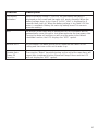
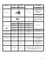
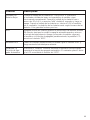
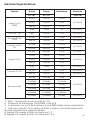
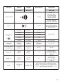
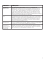
Functions Indication Table
Func-
tion Description
Auto
Range
Auto detects and displays most pertinent range for measured value.
LCD Total of two LCDs (front and bottom). Bottom LCD displays same numbers as
front display for all functions, displays a “-” symbol for all negative readings,
displays “AC” for alternating current or “DC” for direct current and displays
“Amps” for current measurement.
LCD
Backlight
White backlight for both front and bottom display.
Flashlight White flashlight, turns on or off with LCD blacklight simultaneously.
High
Voltage
Alarm
1) Effective setting: ACV / DCV.
2) In ACV/DCV, voltage measurement value: ACV/DCV ≥30V, LCD displays
high voltage alarm lightning symbol
“ ” Simultaneously the NCV LED is on and beeping lasts
for 1 second and then goes silent during measurement.
3) In voltage measure, the voltage data is out of range and LCD displays “OL”,
and high voltage alarm lightning symbol
“ ” Simultaneously NCV LED is on and beeping lasts
for 1 second and then goes silent during measurement.
Regular
Prompt
1) When turning the dial switch to any setting position except OFF, the buzzer
will beep one time and NCV LED flashes one time.
2) When the button selection is valid, the buzzer will beep one time; When the
button is invalid, the buzzer will beep twice
3) About 1 minute before the automatic shutdown, the buzzer will beep 5 times
continuously, and 1 long beep before the unit shuts down.
4) When the automatic shutdown function is canceled, the buzzer will beep 5
times when it reaches the APO time setting.
Over
Range
Indication
LCD displays “OL” when over range is encountered.
La page est en cours de chargement...
La page est en cours de chargement...
La page est en cours de chargement...
La page est en cours de chargement...
La page est en cours de chargement...
La page est en cours de chargement...
La page est en cours de chargement...
La page est en cours de chargement...
La page est en cours de chargement...
La page est en cours de chargement...
La page est en cours de chargement...
La page est en cours de chargement...
La page est en cours de chargement...
La page est en cours de chargement...
La page est en cours de chargement...
La page est en cours de chargement...
La page est en cours de chargement...
La page est en cours de chargement...
La page est en cours de chargement...
La page est en cours de chargement...
La page est en cours de chargement...
La page est en cours de chargement...
La page est en cours de chargement...
La page est en cours de chargement...
La page est en cours de chargement...
La page est en cours de chargement...
La page est en cours de chargement...
La page est en cours de chargement...
La page est en cours de chargement...
La page est en cours de chargement...
La page est en cours de chargement...
La page est en cours de chargement...
La page est en cours de chargement...
La page est en cours de chargement...
La page est en cours de chargement...
La page est en cours de chargement...
La page est en cours de chargement...
La page est en cours de chargement...
La page est en cours de chargement...
La page est en cours de chargement...
La page est en cours de chargement...
La page est en cours de chargement...
La page est en cours de chargement...
La page est en cours de chargement...
La page est en cours de chargement...
La page est en cours de chargement...
La page est en cours de chargement...
La page est en cours de chargement...
La page est en cours de chargement...
La page est en cours de chargement...
La page est en cours de chargement...
La page est en cours de chargement...
La page est en cours de chargement...
La page est en cours de chargement...
La page est en cours de chargement...
La page est en cours de chargement...
La page est en cours de chargement...
La page est en cours de chargement...
La page est en cours de chargement...
La page est en cours de chargement...
La page est en cours de chargement...
La page est en cours de chargement...
La page est en cours de chargement...
La page est en cours de chargement...
-
 1
1
-
 2
2
-
 3
3
-
 4
4
-
 5
5
-
 6
6
-
 7
7
-
 8
8
-
 9
9
-
 10
10
-
 11
11
-
 12
12
-
 13
13
-
 14
14
-
 15
15
-
 16
16
-
 17
17
-
 18
18
-
 19
19
-
 20
20
-
 21
21
-
 22
22
-
 23
23
-
 24
24
-
 25
25
-
 26
26
-
 27
27
-
 28
28
-
 29
29
-
 30
30
-
 31
31
-
 32
32
-
 33
33
-
 34
34
-
 35
35
-
 36
36
-
 37
37
-
 38
38
-
 39
39
-
 40
40
-
 41
41
-
 42
42
-
 43
43
-
 44
44
-
 45
45
-
 46
46
-
 47
47
-
 48
48
-
 49
49
-
 50
50
-
 51
51
-
 52
52
-
 53
53
-
 54
54
-
 55
55
-
 56
56
-
 57
57
-
 58
58
-
 59
59
-
 60
60
-
 61
61
-
 62
62
-
 63
63
-
 64
64
-
 65
65
-
 66
66
-
 67
67
-
 68
68
-
 69
69
-
 70
70
-
 71
71
-
 72
72
-
 73
73
-
 74
74
-
 75
75
-
 76
76
-
 77
77
-
 78
78
-
 79
79
-
 80
80
-
 81
81
-
 82
82
-
 83
83
-
 84
84


Ideal 400A AC/DC TRMS TightSight® Clamp Meter Manuel utilisateur
- Catégorie
- Multimètres
- Taper
- Manuel utilisateur
- Ce manuel convient également à
dans d''autres langues
Documents connexes
Autres documents
-
Klein Tools CL700 Manuel utilisateur
-
Ega Master 51719 Le manuel du propriétaire
-
DirekTronik 20114274 Le manuel du propriétaire
-
KPS DCM3500T Le manuel du propriétaire
-
KRAFTWERK 31130 Mode d'emploi
-
LEXMAN 3151700 Mode d'emploi
-
Amprobe AM555 Le manuel du propriétaire
-
-
-
 LEXMAN LX-M-2000 Mode d'emploi
