
1Part no. CB-209-1441 07/06/2022
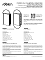
Murray Hill Collection
© 2022 Robern, Inc. 701 N. Wilson Ave. Bristol, PA 19007 U.S.A.
800.877.2376 www.robern.com
MURRAY HILL COLLECTION
INSTALLATION INSTRUCTIONS
Important safety instructions - Save these instructions
Safety - 2
Tools needed - 2
Accessories - 2
Parts - 3
Dimensions - 4
Mount the Frame - 6
Mount the Cabinet - 7
Push-to-Open Installation - 8
Final Assembly - 10
Use and Maintenance - 12
Warranty - 12
CONTENTS
This instruction manual contains information on how to mount a Murray Hill Series framed cabinet. This series comes in dierent sizes.
Refer to the specic model numbers for dimensions. The framed cabinets can only be recess mounted.
Save these instructions for future use and reference. An improper installation voids the warranty. Installed cabinets cannot be returned.
If you experience any problems with your cabinet, contact your dealer or Robern directly.
Limited Warranty — One Year Term
GENERAL INFORMATION
Scan the QR code
to see the entire
Murray Hill Series
of cabinets.
Use the camera app on your
mobile device to look at this and
other QR codes. This will allow
you to quickly access web pages
and other relevant documents.

2Part no. CB-209-1441 07/06/2022
Murray Hill Collection
© 2022 Robern, Inc. 701 N. Wilson Ave. Bristol, PA 19007 U.S.A.
800.877.2376 www.robern.com
SAFETY
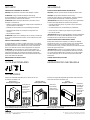
IMPORTANT SAFETY INSTRUCTIONS
DANGER: Read all instructions before using this cabinet.
CAUTION: Maximum shelf load 34lbs/15.4kg
When using an electrical furnishing, basic precautions should always be followed, including the following:
WARNING: To reduce the risk of burns, re, electric shock, or injury to persons:
• Use this furnishing only for its intended use as described in these instructions.
• Do not use attachments not recommended by the manufacturer.
• Never drop or insert any object into any opening.
• Do not use outdoors.
WARNING: Risk of electric shock. Connect this furnishing to a properly grounded circuit only. See Grounding instructions.
GROUNDING INSTRUCTIONS
Electrical option cabinet must be connected to a grounded metal, permanent wiring system, or an equipment-grounding conductor must
be run with the circuit conductors and connected to the equipment-grounding terminal or lead on the product.
WARNING: Electrical option cabinet must be wired to a Class A 20 Amp GFCI (Ground Fault Circuit Interrupter) protected circuit when
used in bathrooms and all other locations required by the National Electric Code.
SAVE THESE INSTRUCTIONS
TOOLS NEEDED
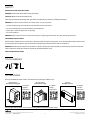
ACCESSORIES
Scan the available QR codes to learn more about these accessories at Robern.com
[P2ELECTRIC*]
Portray Electric Upgrade
For Electric
Upgrade
Instructions:
[QUICKCADDY*]
Portray Quick Caddy
For Quick
Caddy
Instructions:
[DLB-20]
IQ Digital Lock Box
TM
For Digital
Lock Box
Instructions:
*Murray Hill models ending in "TP" include the Portray Electric Upgrade and Quick Caddy.

3Part no. CB-209-1441 07/06/2022
Murray Hill Collection
© 2022 Robern, Inc. 701 N. Wilson Ave. Bristol, PA 19007 U.S.A.
800.877.2376 www.robern.com
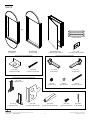
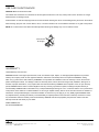
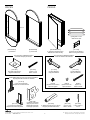
PARTS
(3) Glass Shelves
[211-1329]
(2) Robern Logo Coverplates
[SS672]
(6) Screw Caps
[216-1201] Cabinet Hardware Bag
[211-1376]
(3) Shelf Clips
[211-1377]
(3) Shelf Clips
[P2C2030D4FPSC*]
(1) Portray Series Cabinet
[SS134]
(10) Hole Plugs
[SS674]
(6) #10 x 2" Screws
OR
[DF2050MPXX]
(1) Pill Frame
[DF2040MAXX]
(1) Arch Frame
[216-1237] Frame Hardware Bag
[203-1435]
(12) #8 x 1-1/2" Screws
[211-1453]
(2) Alignment Angles
[P2PUSHKIT] Push-to-Open Hardware Bag
[220-1236]
(1) Push-To-Open Drill Jig
[211-1412]
(1) RH Door Corner
[211-1413]
(1) LH Door Corner
[203-1539]
(1) Push-To-Open Mechanism
[203-1493]
(4) 6-32 x 3/8" Screws
[203-1546]
(1) #31 Drill Bit

4Part no. CB-209-1441 07/06/2022
Murray Hill Collection
© 2022 Robern, Inc. 701 N. Wilson Ave. Bristol, PA 19007 U.S.A.
800.877.2376 www.robern.com
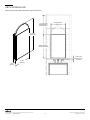
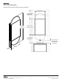
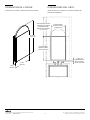
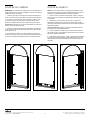
ARCH DIMENSIONS
3-3/4"
(95 mm)
39-15/16"
(1014 mm)
19-1/2"
(495 mm)
Using the views shown below, determine rough-in dimensions.
11” (279.4 mm)
Minimum RO to
finished ceiling
1” (25.4 mm)
Minimum frame
to faucet
Rough Opening:
19” (482.6 mm)
Rough Opening:
29-3/4” (755.6 mm)

5Part no. CB-209-1441 07/06/2022
Murray Hill Collection
© 2022 Robern, Inc. 701 N. Wilson Ave. Bristol, PA 19007 U.S.A.
800.877.2376 www.robern.com
PILL DIMENSIONS
3-3/4"
(95 mm)
19-1/2"
(495 mm)
B
49-1/2"
(1257 mm)
Using the views shown below, determine rough-in dimensions.
Rough Opening:
19” (482.6 mm)
11” (279.4 mm)
Minimum RO to
finished ceiling
3”-4” (76-102 mm)
Recommended
Minimum frame
to vanity top
Rough Opening:
29-3/4” (755.6 mm)
11” (279.4 mm)
Minimum RO to
vanity top

6Part no. CB-209-1441 07/06/2022
Murray Hill Collection
© 2022 Robern, Inc. 701 N. Wilson Ave. Bristol, PA 19007 U.S.A.
800.877.2376 www.robern.com
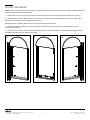
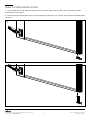
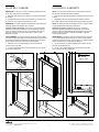
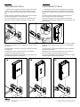
MOUNT THE FRAME
NOTE: The frame comes wrapped in a protective lm. Partial removal of the protective lm will protect the frame during installation and
make removal easier at the end of installation.
1. Insert the frame into the rough opening. Square and plumb the frame, shimming as needed to hold it's position in the opening.
2. Holding a level to the frame, attach the frame to one side of the rough-in using the included at head screws [203-1435]. Shim
behind the screw locations to avoid overtightening the screws.
Pro tip: Add a layer of masking tape to the level to avoid scratching the frame surfaces.
3. Insert and tighten the opposite hand upper and lower screws to level the frame. Shim behind the screw locations to avoid
overtightening the screws.
4. Holding a level to the frame, insert and tighten the remaining screws. To avoid overtightening and potentially damaging the frame,
shim behind the remaining screw locations as required.
2 3 4

7Part no. CB-209-1441 07/06/2022
Murray Hill Collection
© 2022 Robern, Inc. 701 N. Wilson Ave. Bristol, PA 19007 U.S.A.
800.877.2376 www.robern.com
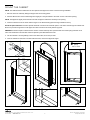
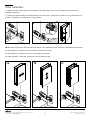
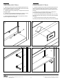
MOUNT THE CABINET
1
[SS674]
#10 x 2" Screw
2
3 4
5
NOTE: The cardboard sleeve attached to the door protects the edges and corners of the door during installation.
1. Remove door from cabinet by taking the hinges o of the mounting plates.
2. Peel the adhesive from each included alignment angle [211-1453] and attach to the lower corners of the frame opening.
NOTE: The alignment angles protect the frame as well as align the cabinet box vertically in the opening.
3. Insert the cabinet box into the frame with the hinges on the desired side (right-hand hinge orientation shown).
Electrical Option Cabinets: Provide a separate electrical connections for electrical options. Pull electric wire through the cabinet hole.
Be sure to provide enough wire to make proper and safe connections to Portray Electric Upgrade.
WARNING: An Electrical option cabinet must be wired to a Class A 20 Amp GFCI (Ground Fault Circuit Interrupter) protected circuit
when used in bathrooms and all other locations required by the National Electric Code.
4. Use the included 2" screws [SS674] to mount the cabinet box, two screws per side.
5. Once the cabinet box has been mounted inside the frame, remove the alignment angles.

8Part no. CB-209-1441 07/06/2022
Murray Hill Collection
© 2022 Robern, Inc. 701 N. Wilson Ave. Bristol, PA 19007 U.S.A.
800.877.2376 www.robern.com
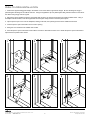
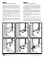
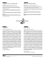
PUSH-TO-OPEN INSTALLATION
1. Position the supplied drill jig [220-1236] in the bottom corner of the cabinet, opposite the hinges. Be sure the ange of the jig is
pressed against the ange of the cabinet as shown. Using the supplied #31 (0.120") drill bit [203-1546], drill three holes into the side of
the cabinet using the jig holes as a guide.
2. Remove the jig and position the push-to-open base plate as shown so all three screw holes line up with the drilled holes. Using a
#2 Phillips-head screwdriver, insert the supplied #6-32 screws [203-1493] and mount the base plate in place.
3. Clip the push-to-open cover onto the baseplate, starting in the back, then pressing inward until an audible click is heard.
4. Insert the push-to-open mechanism into the cover's opening.
5. Swing the cover closed until an audible click is heard.
6. Press the push-to-open mechanism inward until the front face is ush with the outer cover. Rotate the push-to-open mechanism to
adjust the door's position when closed.
1 2 3
4 5 6

9Part no. CB-209-1441 07/06/2022
Murray Hill Collection
© 2022 Robern, Inc. 701 N. Wilson Ave. Bristol, PA 19007 U.S.A.
800.877.2376 www.robern.com
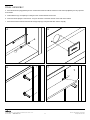
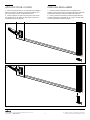
PUSH-TO-OPEN INSTALLATION
7. Lay the cabinet door on a at, protected surface and remove the lower plastic corner by pushing rmly on the bumper until the
corner slides out of the channel.
8. Insert and press the included push-to-open door corner [right-hand corner shown, 211-1412] into the channel until completely seated
and secure.
7
8

10 Part no. CB-209-1441 07/06/2022
Murray Hill Collection
© 2022 Robern, Inc. 701 N. Wilson Ave. Bristol, PA 19007 U.S.A.
800.877.2376 www.robern.com
FINAL ASSEMBLY
3A
2
3B 3C
NOTE: The door hinges have a three-way adjustment feature. These adjustments can be made using a #2 Phillips-head screwdriver.
3A. Side adjustment – Rotate front screw to increase or decrease door overlay.
3B. Height adjustment – Rotate cam screw on mounting plate to adjust door.
3C. Depth adjustment – Rotate rear spiral tech cam screw to adjust door gap.
1. Align the door and reattach hinges to mounting plates until audible click is heard. Ensure all hinges are fully seated before
attempting to adjust door.
2. If desired, the slow close feature can be deactivated on one of the hinges. Swing the door closed once for the deactivation to be
complete. To reactivate, move switch back to original position.
1

11 Part no. CB-209-1441 07/06/2022
Murray Hill Collection
© 2022 Robern, Inc. 701 N. Wilson Ave. Bristol, PA 19007 U.S.A.
800.877.2376 www.robern.com
FINAL ASSEMBLY
4. Press the shelf hole plugs [SS143] into the unused holes inside the cabinet. Place the screw head caps [SS672] over any exposed
screw heads.
5. Install a Robern logo coverplate [211-1329] into each unused electrical access hole.
6. Insert clear shelf clips [221-1376 and 211-1377] into the holes in the back channel on the sides of the cabinet.
7. Push the back of the shelf into both the left and right clips (A). Snap the shelf down into the clips (B).
6
4 5
7
A
B

12 Part no. CB-209-1441 07/06/2022
Murray Hill Collection
© 2022 Robern, Inc. 701 N. Wilson Ave. Bristol, PA 19007 U.S.A.
800.877.2376 www.robern.com
Limited Warranty One Year Term
ROBERN warrants to the original purchaser that, it will, at its election repair, replace, or make appropriate adjustment to products
made by this company shown to have signicant defects in material or workmanship which are reported to ROBERN in writing
within one (1) year from the date of delivery. ROBERN is not responsible for installation costs. The warranty is void in the event the
product is damaged in transit, or if damage or failure is caused by abuse, misuse, abnormal usage, faulty installation, damage in an
accident, improper maintenance, or any repairs other than those authorized by ROBERN. At the expiration of the one year warranty
period, ROBERN shall be under no further obligation under any warranty, expressed or implied, including the implied warranty of
merchantability. ROBERN shall not be liable for any consequential damages arising out of or in connection with the use or performance
of its products. Some states do not allow limitations on how long an implied warranty lasts or do not allow the exclusion or limitation of
incidental or consequential damages, so the above limitation or exclusion may not apply to you. Any liability against ROBERN under
any implied warranty, including the warranty of merchantability, is expressly limited to the terms of this warranty. Permission to return
any merchandise under this warranty must be authorized by ROBERN and returned prepaid by the purchaser. Claims under this
warranty should be sent directly to your dealer.
©2022 ROBERN, INC.
ALL RIGHTS RESERVED
WARRANTY
USE AND MAINTENANCE
CAUTION: Maximum shelf load 34 LBS
The cabinet door and interior are constructed of mirrored glass and aluminum. Use only a damp cloth to clean. Ammonia or vinegar-
based cleaners can damage mirrors.
A 50/50 solution of water and isopropyl alcohol is recommended for cleaning the mirrors. A mild detergent may be used on the surfaces.
When cleaning, spray the cloth, not the cabinet, mirror, or surround surfaces. Do not use abrasive cleansers on any part of the product.
NOTE: Do not store items in the cabinet area directly behind the hinge as damage may occur to cabinet or items.
No Ammonia
Sans Ammoniac
Sin Amoniaco
No Vinegar
Sans Vinaigre
Sin Vinagre
No Ammonia
No Vinegar

1No. de pièce / Pieza n.° CB-209-1441 07/06/2022
Murray Hill Collection / Murray Hill Colección
© 2022 Robern, Inc. 701 N. Wilson Ave. Bristol, PA 19007 U.S.A.
800.877.2376 www.robern.com
Sécurité - 2
Outils Nécessaires - 2
Accessoires - 2
Pièce - 3
Dimensions - 4
Montez le Châssis - 6
Monter l'Cabinet - 7
Appuyez-Pour-Ouvrir - 8
Assemblage Final - 10
Utilisation et Entretien - 12
Garantie - 12
Seguridad - 2
Herramientas Necesarias - 2
Accesorios - 2
Piezas - 3
Dimensiones - 4
Monte el Marco - 6
Montar el Gabinete - 7
Empujar-Para-Abrir - 8
Ensamblado Final - 10
Uso y Mantenimiento - 12
Garantía - 12
Ce manuel d'instructions contient des informations sur la façon de
monter une armoire encadrée de la série Murray Hill. Cette série est
disponible en diérentes tailles. Reportez-vous aux numéros de modèle
spéciques pour les dimensions. Les armoires encadrées peuvent
uniquement être encastrées.
Conservez ces instructions pour une utilisation future et pour référence.
Une mauvaise installation annule la garantie. Les armoires installées ne
peuvent pas être retournées.
Si vous rencontrez des problèmes avec votre armoire, contactez votre
revendeur ou Robern directement.
Garantie limitée — Durée d'un an
Este manual de instrucciones contiene información sobre cómo montar
un gabinete enmarcado de la serie Murray Hill. Esta serie viene en
diferentes tamaños. Consulte los números de modelo especícos para
conocer las dimensiones. Los gabinetes enmarcados solo se pueden
montar empotrados.
Guarde estas instrucciones para uso y referencia en el futuro. Una
instalación incorrecta anula la garantía. Los gabinetes instalados no se
pueden devolver.
Si tiene algún problema con su gabinete, comuníquese con su
distribuidor o con Robern directamente.
Garantía limitada — Término de un año
TABLE DES MATIÈRES CONTENIDO
INFORMATION GÉNÉRALES INFORMACIÓN GENERAL
Scannez le code
QR pour voir toute
la série d'cabinets
Murray Hill.
Escanee el código
QR para ver toda la
serie de gabinetes
Murray Hill.
Utilisez l'application appareil photo sur votre appareil mobile
pour consulter ce code QR et d'autres. Cela vous permettra
d'accéder rapidement aux pages Web et autres documents
pertinents.
Use la aplicación de la cámara en su dispositivo móvil para ver
este y otros códigos QR. Esto le permitirá acceder rápidamente
a páginas web y otros documentos relevantes.
MURRAY HILL COLLECTION / COLECCIÓN
INSTRUCTIONS D'INSTALLATION
Consignes de sécurité importantes - Conservez ces consignes
INSTRUCCIONES DE INSTALACIÓN
Instrucciones de seguridad importantes - Guarde estas instrucciones

2No. de pièce / Pieza n.° CB-209-1441 07/06/2022
Murray Hill Collection / Murray Hill Colección
© 2022 Robern, Inc. 701 N. Wilson Ave. Bristol, PA 19007 U.S.A.
800.877.2376 www.robern.com
SÉCURITÉ SEGURIDAD
PRINCIPALES CONSIGNES DE SÉCURITÉ
DANGER: Lisez toutes les instructions avant d'utiliser ce boîtier.
ATTENTION: Charge maximale de l'étagère 34lbs/15,4kg
En cas d'utilisation d'un meuble électrique, il convient de prendre des
précautions de base, notamment les suivantes :
ATTENTION! Réduire les risques de brûlures, d'incendie, de choc
électrique ou de blessures :
• Utilisez ce meuble uniquement pour l'usage auquel il est destiné, tel
que décrit dans ces instructions.
• N'utilisez pas d'accessoires non recommandés par le fabricant.
• Ne laissez jamais tomber ou n'insérez aucun objet dans une
ouverture.
• Ne pas utiliser à l'extérieur.
ATTENTION! Risque de choc électrique. Ne connectez ce meuble que
sur un circuit correctement mis à la terre. Voir les instructions de mise
à la terre.
INSTRUCTIONS DE MISE À LA TERRE
Ce produit doit être connecté à un métal mis à la terre, à un système
de câblage permanent, ou un câble de mise à la terre de l'équipement
doit être acheminé avec les conducteurs du circuit et connecté à la
borne ou au câble de mise à la terre de l'équipement sur le produit.
ATTENTION! L'armoire électrique en option doit être câblée à un
circuit protégé par un disjoncteur de fuite à la terre (GFCI ou Ground
Fault Circuit Interrupter) de classe A de 20 ampères lorsqu'elle est
utilisée dans les salles de bain et dans tous les autres endroits requis
par le code national de l'électricité.
ENREGISTREZ CES INSTRUCTIONS
INSTRUCCIONES IMPORTANTES DE SEGURIDAD
PELIGRO: Antes de usar este armario lea todas las instrucciones.
CUIDADO: Carga máxima del estante 34 lbs/15,4 kg
Cuando se vaya a utilizar un mueble eléctrico, siempre se deberán
seguir las precauciones básicas, incluidas las siguientes:
¡ADVERTENCIA! Para reducir el riesgo de que ocurran quemaduras,
incendios, descargas eléctricas o lesiones a las personas:
• Use este mueble solo para el uso previsto como se describe en
estas instrucciones.
• No utilice accesorios no recomendados por el fabricante.
• Nunca deje caer ni inserte ningún objeto en ninguna abertura.
• No lo use al aire libre.
¡ADVERTENCIA! Riesgo de descarga eléctrica. Conecte este aparato
únicamente a un circuito que esté debidamente conectado a tierra.
Consulte las instrucciones para las conexiones a tierra.
INSTRUCCIONES PARA CONEXIONES A TIERRA
Este producto deberá estar conectado a un sistema de cableado
permanente de metal y con conexión a tierra, de lo contrario deberá
instalar un conductor de conexión a tierra del equipo con los
conductores del circuito y conectarlo al terminal o al cable de conexión
a tierra del equipo del producto.
¡ADVERTENCIA! Cuando se vaya a utilizar en baños y el resto de
ubicaciones requeridas por el Código Eléctrico Nacional, el armario
con opción eléctrica deberá estar conectado a un circuito protegido
con GFCI (interruptor de circuito de toma de tierra) de clase A de
20 amperios.
GUARDE ESTAS INSTRUCCIONES
OUTILS NÉCESSAIRES
ACCESSORIES
Scannez les codes QR disponibles pour en savoir plus sur ces
accessoires sur Robern.com
[P2ELECTRIC*]
Portray Electric Upgrade
Instructions de
mise à niveau
électrique:
Instrucciones
de actualización
eléctrica:
[QUICKCADDY*]
Portray Quick Caddy
Instructions
Quick Caddy:
Instrucciones
de Quick Caddy:
[DLB-20]
IQ Digital Lock Box
TM
Instructions
du boîtier de
verrouillage
numérique:
Instrucciones
de caja de
seguridad
digital:
*Les modèles Murray Hill se terminant par "TP" incluent la mise à
niveau électrique Portray et le Quick Caddy.
*Los modelos de Murray Hill que terminan en "TP" incluyen Portray
Electric Upgrade y Quick Caddy.
HERRAMIENTAS NECESARIAS
Escanee los códigos QR disponibles para obtener más información
sobre estos accesorios en Robern.com

3No. de pièce / Pieza n.° CB-209-1441 07/06/2022
Murray Hill Collection / Murray Hill Colección
© 2022 Robern, Inc. 701 N. Wilson Ave. Bristol, PA 19007 U.S.A.
800.877.2376 www.robern.com
Ou / O
[DF2050MPXX]
(1) Pill Frame
[DF2040MAXX]
(1) Arch Frame
[216-1237] Sac de Matériel d'Cadre /
Bolsa de Herrajes para Cuadro
[211-1453]
(2) Angles d'Alignement /
Ángulos de Alineación
[P2PUSHKIT] Appuyez-pour-Ouvrir le Sac de Matériel /
Empujar-para-Abrir la Bolsa de Hardware
[220-1236]
(1) Gabarit de Perçage
Appuyez-pour-Ouvrir /
Plantilla de Perforación
de Empujar-para-Obrir
[211-1412]
(1) Coin de Porte Droite /
Esquina de la Puerta Derecha
[211-1413]
(1) Coin de Porte Gauche /
Esquina de la Puerta Izquierda
[203-1539]
(1) Mécanisme Appuyez-pour-Ouvrir /
Empujar-para-Obrir Mecanismo
[203-1493]
(4) 6-32 x 3/8"
Hélice / Tornillo
[203-1546]
(1) #31 Trépan /
Broca
PIÈCES PIEZAS
(3) Étagères en verre
/ Estantes de vidrio
[211-1329]
(2) Plaque de logo Robern /
Placa con el logo de Robern
[216-1201] Sac de Matériel d'Cabinet /
Bolsa de Hardware del Gabinete
[211-1376]
(3) Clips d'Étagère /
Clips para Estantes
[211-1377]
(3) Clips d'Étagère /
Clips para Estantes
[P2C2030D4FPSC*]
(1) Cabinet de la Série Portray /
Gabinete de la Serie Portray
[SS134]
(10) Bouchons de Trous /
Tapón de Agujero
[SS672]
(6) Bouchon à Vis /
Tapón de Rosca
[SS674]
(6) #10 x 2"
Hélice / Tornillo
[203-1435]
(12) #8 x 1-1/2"
Hélice / Tornillo

4No. de pièce / Pieza n.° CB-209-1441 07/06/2022
Murray Hill Collection / Murray Hill Colección
© 2022 Robern, Inc. 701 N. Wilson Ave. Bristol, PA 19007 U.S.A.
800.877.2376 www.robern.com
DIMENSIONS DE L'ARCHE DIMENSIONES DEL ARCO
À l'aide des vues ci-dessous, déterminez les dimensions brutes. Usando las vistas que se muestran a continuación, determine las
dimensiones de instalación.
3-3/4"
(95 mm)
39-15/16"
(1014 mm)
19-1/2"
(495 mm)
11” (279.4 mm)
Minimum RO to
finished ceiling
1” (25.4 mm)
Minimum frame
to faucet
Rough Opening:
19” (482.6 mm)
Rough Opening:
29-3/4” (755.6 mm)
1" (25.4 mm)
Cadre Minimum au
Robinet / Marco
Mínimo para Grifo
Ouverture Brute /
Apertura en Bruto:
29-3/4" (755.6 mm)
Ouverture brute minimale
au plafond ni / Abertura
aproximada mínima
hasta el techo terminado
11" (279.4 mm)
Ouverture Brute /
Apertura en Bruto:
19" (482.6 mm)

5No. de pièce / Pieza n.° CB-209-1441 07/06/2022
Murray Hill Collection / Murray Hill Colección
© 2022 Robern, Inc. 701 N. Wilson Ave. Bristol, PA 19007 U.S.A.
800.877.2376 www.robern.com
Rough Opening:
19” (482.6 mm)
11” (279.4 mm)
Minimum RO to
finished ceiling
3”-4” (76-102 mm)
Recommended
Minimum frame
to vanity top
Rough Opening:
29-3/4” (755.6 mm)
11” (279.4 mm)
Minimum RO to
vanity top
DIMENSIONS DE LA PILULE DIMENSIONES DE LA PÍLDORA
3-3/4"
(95 mm)
19-1/2"
(495 mm)
B
49-1/2"
(1257 mm)
À l'aide des vues ci-dessous, déterminez les dimensions brutes. Usando las vistas que se muestran a continuación, determine las
dimensiones de instalación.
1" (25.4 mm)
Cadre Minimum
Recommandé
pour le Dessus
de la Vanité /
Marco Mínimo
Recomendado
para la Parte
Superior del
tocador
Ouverture Brute /
Apertura en Bruto:
29-3/4" (755.6 mm)
Ouverture brute minimale
au plafond ni / Abertura
aproximada mínima
hasta el techo terminado
11" (279.4 mm)
Ouverture Brute /
Apertura en Bruto:
19" (482.6 mm)
Ouverture Brute Minimale
au Dessus de la Vanité
/ Abertura aproximada
mínima hasta la parte
superior del tocador
11" (279.4 mm)

6No. de pièce / Pieza n.° CB-209-1441 07/06/2022
Murray Hill Collection / Murray Hill Colección
© 2022 Robern, Inc. 701 N. Wilson Ave. Bristol, PA 19007 U.S.A.
800.877.2376 www.robern.com
MONTEZ LE CHÂSSIS MONTE EL MARCO
2 3 4
NOTA: El marco viene envuelto en una película protectora. La elimi-
nación parcial de la película protectora protegerá el marco durante la
instalación y facilitará la eliminación al nal de la instalación.
1. Inserte el marco en la abertura aproximada. Cuadre y coloque a
plomo el marco, calce según sea necesario para mantener su posición
en la abertura.
2. Sosteniendo un nivel al marco, je el marco a un lado de la
abertura empotrada usando los tornillos de cabeza plana incluidos
[203-1435]. Calce detrás de las ubicaciones de los tornillos para evitar
apretarlos demasiado.
Consejo Profesional: agregue una capa de cinta adhesiva al nivel
para evitar rayar las supercies del marco.
3. Inserte y apriete los tornillos superior e inferior del lado opuesto
para nivelar el marco. Calce detrás de las ubicaciones de los tornillos
para evitar apretarlos demasiado.
4. Sosteniendo un nivel al marco, inserte y apriete los tornillos restan-
tes. Para evitar apretar demasiado y dañar potencialmente el marco,
calce detrás de las ubicaciones restantes de los tornillos según sea
necesario.
REMARQUE: Le cadre est livré enveloppé dans un lm protecteur. Le
retrait partiel du lm de protection protégera le cadre lors de la pose et
facilitera le retrait en n de pose.
1. Insérez le cadre dans l'ouverture brute. Équerrez et aplombez le
cadre, en calant au besoin pour maintenir sa position dans l'ouverture.
2. En tenant un niveau au cadre, xez le cadre à un côté de l'ouver-
ture brute à l'aide des vis à tête plate incluses [203-1435]. Caler
derrière les emplacements des vis pour éviter de trop serrer les vis.
Conseil de Pro: ajoutez une couche de ruban adhésif au niveau pour
éviter de rayer les surfaces du cadre.
3. Insérez et serrez les vis supérieures et inférieures opposées pour
niveler le cadre. Caler derrière les emplacements des vis pour éviter
de trop serrer les vis.
4. En maintenant un niveau sur le cadre, insérez et serrez les vis
restantes. Pour éviter de trop serrer et d'endommager potentiellement
le cadre, calez derrière les emplacements de vis restants au besoin.

7No. de pièce / Pieza n.° CB-209-1441 07/06/2022
Murray Hill Collection / Murray Hill Colección
© 2022 Robern, Inc. 701 N. Wilson Ave. Bristol, PA 19007 U.S.A.
800.877.2376 www.robern.com
MONTER L'CABINET MONTAR EL GABINETE
1
[SS674]
#10 x 2" Screw
2
3 4
5
REMARQUE: Le manchon en carton xé à la porte protège les bords
et les coins de la porte lors de l'installation.
1. Retirez la porte de l'armoire en retirant les charnières des plaques
de montage.
2. Décollez l'adhésif de chaque angle d'alignement inclus [211-1453]
et xez-le aux coins inférieurs de l'ouverture du cadre.
REMARQUE: Les angles d'alignement protègent le cadre et alignent le
boîtier de l'armoire verticalement dans l'ouverture.
Cabinets d'options électriques: fournir des connexions électriques
séparées pour les options électriques. Tirez le l électrique à travers
le trou de l'armoire. Assurez-vous de fournir susamment de l pour
établir des connexions correctes et sûres avec la mise à niveau
électrique du Portrait.
AVERTISSEMENT: Une armoire d'options électriques doit être câblée
à un circuit protégé GFCI (disjoncteur de fuite à la terre) de classe A de
20 ampères lorsqu'elle est utilisée dans les salles de bains et tous les
autres endroits requis par le Code national de l'électricité.
4. Utilisez les vis 2" incluses [SS674] pour monter le boîtier de
l'armoire, deux vis par côté.
5. Une fois la boîte de l'armoire montée à l'intérieur du cadre, retirez
les cornières d'alignement.
NOTA: La funda de cartón adherida a la puerta protege los bordes y
las esquinas de la puerta durante la instalación.
1. Retire la puerta del gabinete quitando las bisagras de las placas de
montaje.
2. Despegue el adhesivo de cada ángulo de alineación incluido
[211-1453] y péguelo a las esquinas inferiores de la abertura del marco.
NOTA: Los ángulos de alineación protegen el marco y también alinean
la caja del gabinete verticalmente en la abertura.
Gabinetes de opciones eléctricas: Proporcione conexiones
eléctricas separadas para las opciones eléctricas. Tire del cable
eléctrico a través del oricio del gabinete. Asegúrese de proporcionar
suciente cable para realizar conexiones adecuadas y seguras a
Portray Electric Upgrade.
ADVERTENCIA: Un gabinete de opciones eléctricas debe conectarse
a un circuito protegido GFCI (Interruptor de circuito por falla a tierra)
Clase A de 20 amperios cuando se usa en baños y en todos los demás
lugares requeridos por el Código Eléctrico Nacional.
4. Use los tornillos de 2" incluidos [SS674] para montar la caja del
gabinete, dos tornillos por lado.
5. Una vez que la caja del gabinete se haya montado dentro del
marco, retire los ángulos de alineación.

8No. de pièce / Pieza n.° CB-209-1441 07/06/2022
Murray Hill Collection / Murray Hill Colección
© 2022 Robern, Inc. 701 N. Wilson Ave. Bristol, PA 19007 U.S.A.
800.877.2376 www.robern.com
APPUYEZ-POUR-OUVRIR
1 2 3
4 5 6
EMPUJAR-PARA-ABRIR
1. Positionnez le gabarit de perçage fourni [220-1236] dans le coin
inférieur de l'armoire, à l'opposé des charnières. Assurez-vous que
la bride du gabarit est appuyée contre la bride de l'armoire, comme
illustré. À l'aide du foret #31 (0,120") fourni [203-1546], percez trois
trous dans le côté de l'armoire en utilisant les trous du gabarit comme
guide.
2. Retirez le gabarit et positionnez la plaque de base push-to-open
comme illustré de sorte que les trois trous de vis soient alignés avec
les trous percés. À l'aide d'un tournevis cruciforme n° 2, insérez les vis
n° 6-32 fournies [203-1493] et montez la plaque inférieure en place.
3. Clipsez le couvercle push-to-open sur la plaque inférieure, en
commençant par l'arrière, puis en appuyant vers l'intérieur jusqu'à ce
qu'un déclic se fasse entendre.
4. Insérez le mécanisme push-to-open dans l'ouverture du couvercle.
5. Faites pivoter le couvercle pour le fermer jusqu'à ce qu'un déclic se
fasse entendre.
6. Appuyez sur le mécanisme push-to-open vers l'intérieur jusqu'à ce
que la face avant soit alignée avec le couvercle extérieur. Tournez le
mécanisme push-to-open pour ajuster la position de la porte lorsqu'elle
est fermée.
1. Coloque la plantilla de perforación suministrada [220-1236] en la
esquina inferior del gabinete, frente a las bisagras. Asegúrese de que
la brida de la plantilla esté presionada contra la brida del gabinete
como se muestra. Con la broca n.° 31 (0,120") suministrada [203-
1546], taladre tres oricios en el costado del gabinete utilizando los
oricios de plantilla como guía.
2. Retire la plantilla y coloque la placa base de empujar para abrir
como se muestra, de modo que los tres oricios para tornillos se
alineen con los oricios perforados. Con un destornillador de cabeza
Phillips n.° 2, inserte los tornillos n.° 6-32 suministrados [203-1493] y
monte la placa inferior en su lugar.
3. Enganche la tapa de empujar para abrir en la placa inferior,
comenzando por la parte posterior y luego presionando hacia adentro
hasta que se escuche un clic.
4. Inserte el mecanismo de empujar para abrir en la abertura de la
cubierta.
5. Gire la cubierta para cerrarla hasta que se escuche un clic audible.
6. Presione el mecanismo de empujar para abrir hacia adentro
hasta que la cara frontal quede al ras con la cubierta exterior. Gire el
mecanismo de empujar para abrir para ajustar la posición de la puerta
cuando esté cerrada.
La page est en cours de chargement...
La page est en cours de chargement...
La page est en cours de chargement...
La page est en cours de chargement...
-
 1
1
-
 2
2
-
 3
3
-
 4
4
-
 5
5
-
 6
6
-
 7
7
-
 8
8
-
 9
9
-
 10
10
-
 11
11
-
 12
12
-
 13
13
-
 14
14
-
 15
15
-
 16
16
-
 17
17
-
 18
18
-
 19
19
-
 20
20
-
 21
21
-
 22
22
-
 23
23
-
 24
24


Robern Murray Hill Collection Guide d'installation
- Taper
- Guide d'installation
- Ce manuel convient également à
dans d''autres langues
Documents connexes
-
Robern Murray Hill Manuel utilisateur
-
Robern EDGEPULL-84 Manuel utilisateur
-
Robern P2PUSHKIT Manuel utilisateur
-
Robern MPUSHKIT Manuel utilisateur
-
Robern VT-SPOMM Manuel utilisateur
-
Robern CRAFT Series Manuel utilisateur
-
Robern CM2430W20369 Manuel utilisateur
-
-
-