Modern Forms FR-W2101 Wynd XL Mode d'emploi
- Catégorie
- Ventilateurs ménagers
- Taper
- Mode d'emploi

Wynd XL
Installation Instructions
works with the
Google Assistant

FR-W2101
Wynd XL Instructions2
Please read and
save these instructions
before installation
DO NOT RETURN TO STORE

FR-W2101Wynd XL Instructions 3
For all questions about your ceiling fan please read all included
instructions, installation procedures, troubleshooting guidelines
and warranty information before starting installation.
For missing parts or general inquiries call our trained technical staff at:
1-866-810-6615 option 1
MON-FRI 8AM-8PM EST
Email: customerservice@modernforms.com
Or live chat at modernforms.com
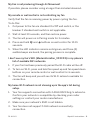
For fast service have the following information below when you call:
1. Model Name and Number
2. Part Number and Part Description
3. Date Of Purchase and Purchase Location
1-866-810-6615 option 2
MON-FRI 8AM-8PM EST
Email: fansupport@modernforms.com
General Inquiries
Fan Support

FR-W2101
Wynd XL Instructions4
For operation, maintenance, and troubleshooting information,
visit http://modernforms.com/fan-support/
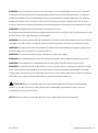
To reduce the risk of electric shock, ensure electricity has been turned off at the circuit breaker
before beginning. All wiring must be in accordance with the National Electrical Code “ANSI/NFPA
70” and local electrical codes. Electrical installation should be performed by a licensed electrician.
The fan must be mounted with a minimum of 7 ft. (2.1m) clearance from the trailing edge of
the fan blades to the floor and a minimum of 1.5 ft (0.5m) from the edge of the fan blades to the
surrounding walls. Never place objects in the path of the fan blades. To avoid personal injury or
damage to the fan and other items, please be cautious when working around or cleaning the fan.
To avoid electrical shock or damage to the motor or finish, do not use water or chemicals
when cleaning the fan or fan blades. A dry cloth or lightly dampened cloth will be suitable
for most cleaning.
After making electrical connections, spliced conductors should be turned upward and pushed
carefully up into the outlet box. The wires should be spread apart with the grounded conductor and
the equipment-grounding conductor on one side of the outlet box, and the ungrounded conductor
on the other side of the outlet box.
All set screws must be checked and re-tightened
where necessary before installation.
Safety Rules

FR-W2101 Wynd XL Instructions 5
WARNING: Do not install or use your fan if any part(s) is/are damaged or missing. This product
is designed for use only with the supplied parts and/or accessories designated for use with this
product by Modern Forms. Substitution of parts or accessories not designated for use with this
product by Modern Forms could result in personal injury or property damage and will void the
warranty. Contact an authorized dealer or the manufacturer if any parts are damaged or missing.
WARNING: To reduce the risk of electric shock, this fan must
be installed and operated with the supplied wall control, or controlled from the Modern Forms app
or Wi-Fi Touch Panel Wall Control (not included).
WARNING: Do not use power tools to assemble or install your fan. Using power tools can result in
improper assembly which can lead to noise or fan damage,personal injury or property damage.
WARNING: To reduce the risk of personal injury, do not bend the blade arms when installing the
brackets, balancing the blades or cleaning the fan.
WARNING: Do not insert foreign objects between rotating fan blades.
WARNING: Do not operate fan unless fan blades are in place. Noise and fan damage can occur
WARNING: This appliance is not intended for use by young children without supervision.
WARNING: To reduce the risk of fire, electric shock, personal injury or damage to the fan or other
items, the outlet box and support structure must be securely mounted and capable of reliably
supporting a minimum of 35 Ibs (15.9 kg). Use only UL/cUL listed outlet boxes marked “FOR FAN
SUPPORT.” Use only the screws and washers provided with the outlet box.
CAUTION: Before assembling your fan, refer to the “Making the Electrical Connections“
section. If you feel you do not have enough wiring knowledge or experience, have your fan
installed by a licensed electrician.
NOTE: Before servicing or cleaning the fan, switch power off at the circuit breaker.

FR-W2101
Wynd XL Instructions6
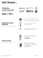
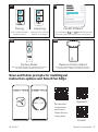
Get Smart...
Integrates
seamlessly with:
devices you already own
works with the
Google Assistant
Premium smart
features:
Accessories:
DC
MOTOR
complement high quality materials
personalize your experience
Quiet, reliable, and up to 70%
more ecient than AC fans
Wi-Fi and Bluetooth enabled
for exible control
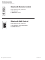
Bluetooth Wall Control
Dims light to 1% | ON/OFF
6 fan speeds | Sold separately
F-WCBT-WT White
Bluetooth Remote Control
Dims light to 1% | ON/OFF
6 fan speeds
F-RCBT-WT White
Wet Location-listed to the strictest
UL/cUL safety regulations. Finished
and rated for interior and exterior use

FR-W2101 Wynd XL Instructions 7
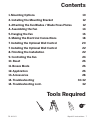
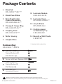
Contents
Tools Required
1. Mounting Options 10
2. Installing the Mounting Bracket 12
3. Attaching the Fan Blades / Blade Press Plates 12
4. Assembling the Fan 14
5. Hanging the Fan 16
6. Making the Electrical Connections 18
7. Installing the Optional Wall Control 20
7. Installing the Optional Wall Control 22
8. Finishing the Installation 22
9. Controlling the Fan 24
10. Reset 26
11. Breeze Mode 26
12. Application 26
13. Accessories 28
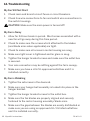
14. Troubleshooting 30-32
14. Troubleshooting cont. 32

FR-W2101
Wynd XL Instructions8
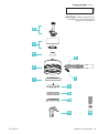
Package Contents
8. Luminaire Module
F4IN-120V-R1-30
9. Luminaire Cover
RPL-F2101-COVER-**
10. Acrylic Shade
RPL-F1801-GLA
11. Control receiver
w/Hardware (***)
F-R3-2101-072
12. Remote w/Wall Cradle
F-RCBT-WT
Hardware Bag
RPL-F2101-**-PARTS
1. Blade Set
RPL-F2101-**-BD-***
2. Blade Press Plates
3. Mounting Bracket
Downrod Assembly
RPL-HGR-ASM-XL-**
4. Canopy & Canopy Ring
RPL-CAN-CYL-XL-**
5. Coupling Cover
RPL-COU-CVR-***
6. Motor Housing
7. Adapter Plate
** denotes finish code of fan
Before discarding packaging materials be certain all parts have been removed.
Place the parts from the hardware bag into a small container to keep them from being lost.
AMachine Screws (2)
Spring Washers (2)
Flat Washers (2)
BScrews with Lock Washers (28)
C
Wood Screw (1)
Spring Washer (1)
Flat Washer (1)
DWire Nuts (11)
(Included with receiver)

FR-W2101 Wynd XL Instructions 9
IMPORTANT: Please make note of
the MAC ID on the receiver and
keep it in a safe place.
MAC ID
12
1
2
4
8
9
10
11
5
6
7
3
Hanging Weight: 35 lbs

FR-W2101
Wynd XL Instructions10
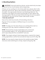
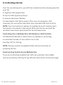
1. Mounting Options
CAUTION: To prevent electrical shock, ensure electricity has been
turned off at the circuit breaker before beginning.
If there isn’t an existing UL/cUL listed outlet box, please refer to the
following instructions. Secure the outlet box directly to the building
structure. Use appropriate fasteners and building materials. The
outlet box and support structure must be able to fully support the
moving weight of the fan (at least 35 lbs/15.9 kg). Do not use plastic
outlet boxes. Use only UL/cUL listed outlet boxes marked
“FOR FAN SUPPORT.”
Secure the outlet box directly to the building structure.
Figures 1-1C are examples of different ways to mount the
outlet box.
NOTE: To hang your fan where there is an existing fixture but no
ceiling joist, you may need an installation hanger bar.
NOTE: Downrod fans can be suspended up to a maximum
recommended length of 72” using additional downrods
(sold separately) and the included 80” lead wire.
NOTE: The sloped ceiling kit (sold separately) is required for sloped
ceiling applications, and will accommodate slopes up to 45° (Fig. 1B).
NOTE: You may need a longer downrod to maintain proper blade
clearance when installing on a steep, sloped ceiling (Fig. 1B).

FR-W2101 Wynd XL Instructions 11
1
1A
1B
1C
1
1
2
1
1
2
3
3
1. Support Brace
2. Outlet Box
3. Joist
1. Support Brace
2. Mounting Bracket
3. Recess Outlet Box
1. Outlet Box
1. Outlet Box
Support Ceiling
Max 30° Angle

FR-W2101
Wynd XL Instructions12
2. Installing the Mounting Bracket
CAUTION: Remember to disconnect the power at the circuit breaker.
1. Remove 1 set screw from mounting bracket and set aside for use in
Finishing the Installation.
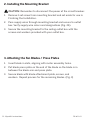
2. Pass supply wires through mounting bracket and secure to outlet
box. Verify supply wire colors and designations (Fig. 2A).
3. Secure the mounting bracket to the ceiling outlet box with the
screws and washers provided with your outlet box.
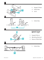
1. Insert blade in slots, aligning with motor assembly holes.
2. Put blade press plate on the end of the blade so the blade is in
between the blade arm and press plate.
3. Secure blade with blade attachment plate, screws, and
washers. Repeat process for the remaining blades. (Fig. 3)
3. Attaching the Fan Blades / Press Plates

FR-W2101 Wynd XL Instructions 13
1. Slot
2. Blade
3. Blade Press Plates
4. Screws with Lock Washers
Refer to Hardware B
2
3
2A
1. Mounting Bracket
2. Screw
Refer to Hardware A
1
3
2
4
1
2
2
3
1
To Switch A
A
B
(HOT)
(Neutral)
(HOT)/
Switch
(No Neutral)
(Ground)
*Bare or Green
(Ground)
*Bare or Green
To Switch
1. cUL Listed Electrical Box
2. Mounting Screws
(outlet box screws not included)
3. 120V Wires

FR-W2101
Wynd XL Instructions14
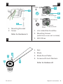
4. Assembling the Fan
CAUTION: Failure to properly install the cotter pin and/or tighten
the set screws could result in the fan loosening and possibly falling.
NOTE: Screws for Adapter plate are preinstalled on the fan motor
assembly on the small ring at the center of the blades. Remove blue
packing ring if present.
1. Remove one screw from the inner ring on the motor assembly
and loosen the other 2 (Fig. 4).
2. Seat the Adapter Plate on the center ring and twist to lock the
keyhole cutouts onto the screws previously loosened (Fig. 4A).
3. Replace the 3rd screw and tighten all 3 until snuggly secured by
hand.
NOTE: Screws for Luminaire Module plate are preinstalled on the
Adapter Plate on the middle ring. Luminaire Module itself comes
preinstalled on its mounting plate.
4. Remove one screw from the adapter plate for the luminaire
module plate and loosen the other 2.
5. Seat the Luminaire Module Plate on the adapter plate and twist
to lock the keyhole cutouts on the screws previously loosened
(Fig. 4B).
6. Replace the 3rd screw and tighten all 3 until snuggly secured.
7. Install acrylic shade without over-tightening or install metal light
cover (Fig. 4C).
NOTE: Add metal light cover if you do not need lighting function or
prefer a different aesthetic.
NOTE: Do not connect the LED connector wires if you are using the
metal light cover.
NOTE: Do not overtighten screws or you may strip the screws or
damage the plating.

FR-W2101 Wynd XL Instructions 15
4 4A
4C4B
1. 3 screws for adapter plate
1. Luminaire
2. Metal Light Cover
OR
1
2
1

FR-W2101
Wynd XL Instructions16
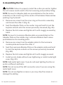
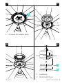
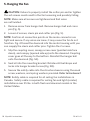
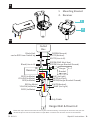
5. Hanging the Fan
CAUTION: Failure to properly install the cotter pin and/or tighten
the set screws could result in the fan loosening and possibly falling.
NOTE: Make sure all screws are tightened and that wires
are not twisted.
1. Remove screw from hanger ball. Remove hanger ball and cross
pin (Fig. 5).
2. Loosen 2 screws, clevis pin and cotter pin (Fig. 5).
NOTE: Confirm all connection points on the molex connector are
tight and secure. If any wires are loose, it may cause the fan to not
function. Fig. 4 thread the downrod into the motor housing until you
can reapply the clevis and cotter pins. Tighten the 2 screws.
3. Slip the coupling cover, canopy screw cover (painted side face
down), and canopy (opened side up) onto the downrod. Coupling
cover goes all the way to the bottom. Reinstall the hanger ball
onto the downrod (Fig. 5A).
4. Seat all into the mounting bracket. Rotate until ball drops and
locks into hanger bracket screw (Fig. 5B).
5. Secure the safety cable into the structure beams using the wood
screw, washers, and spring washers provided. Refer to Hardware C
NOTE: Safety cable is required for all ceiling fan installations in
Canada. Safety cable is required for ceiling fan and light (combo)
installations over 35 lbs. in both flush and downrod models in the
United States.

FR-W2101 Wynd XL Instructions 17
5
5B
5A
1. Canopy
2. Canopy Ring
3. Coupling Cover
4. Molex Connector
5. Clevis Pin
6. Cotter Pin
7. Motor Housing Screws
8. Wood Screw
9. Safety Cable
8
1
4
2
6
7
3
5
9

FR-W2101
Wynd XL Instructions18
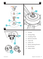
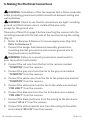
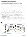
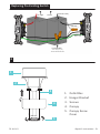
6. Making the Electrical Connections
WARNING: Installation of this fan requires that a three-conductor
cable (including ground wire) which should run between ceiling and
wall outlet box.
WARNING: Check to see that all connections are tight, including
ground, and that no bare wire is visible at the wire nuts,
except for the ground wire.
Take note of Mac ID on page 9 before inserting the receiver into the
mounting bracket with the flat side of the receiver facing the ceiling
(Fig. 6).
1. Motor to Receiver & Receiver to house supply wires (Fig. 6A).
Refer to Hardware D
1. Connect the hanger ball/downrod assembly ground wire,
mounting bracket ground wire and receiver ground wire to
the ground wire in outlet box.
WARNING: Failure to connect ground wires could result in
poor fan control functionality.
2. Connect the red wire from the fan to the red wire marked
“TO MOTOR” from the receiver.
3. Connect the grey wire from the fan to the grey wire marked
“TO MOTOR” from the receiver.
4. Connect the yellow wire from the fan to the yellow wire marked
“TO MOTOR” from the receiver.
5. Connect the white wire from the fan to the white wire marked
“FOR LIGHT” from the receiver.
6. Connect the blue wire from the fan to the blue wire marked
“FOR LIGHT” from the receiver.
7. Connect the black (hot) wire from the ceiling to the black wire
marked “AC in L” from the receiver.
8. Connect the white (neutral) wire from the ceiling to the white
wire marked “AC in N” from the receiver.

FR-W2101 Wynd XL Instructions 19
Follow the steps above to connect the fan to your household wiring. Use the plastic wire nuts with your fan.
Secure the plastic wire nuts with electrical tape. Make sure there are no loose strands or connections.
6
6A
Black(Hot)
can be RED from Switch leg
Black(Line in H)
RED(to Motor)
GREEN(Ground)
BLUE (to Light)
BLUE (for Light)
GREEN(GND Must Use)
GREEN(Hanger Bracket Ground)
GREEN(Hanger Bracket Ground)
RED(to Motor)
GREY(to Motor)
WHITE(Neutral)
WHITE(to Light)
WHITE(Neutral)
Safety Cable
GREY(to Motor)
YELLOW(to Motor)
WHITE(Line in N)
YELLOW(to Motor)
Outlet
Box
Receiver
Hanger Ball & Downrod
Hanger
Bracket
1
2
1. Mounting Bracket
2. Receiver

FR-W2101
Wynd XL Instructions20
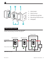
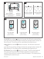
7. Installing the Optional Wall Control
1. Connect the green wire marked “GROUND” from the wall
control to the copper wire from the wall outlet box that
feeds back to the circuit breaker – important for proper
fan function (Fig. 7).
2. Connect the black wire marked “LINE IN” from the wall control to
the black LINE VOLTAGE wire from the wall outlet box that feeds
back to the circuit breaker (Fig. 7).
3. Connect the red wire from the wall control to the black wire from
the wall outlet box that feeds up to the fan (Fig. 7).
4. Connect the white wire from the wall control to the white
(neutral) wire from the wall outlet box (Fig. 7).
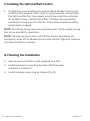
5. Carefully tuck the wire connections inside the outlet box.
Secure the wall control with the two (2) wall control screws
provided (Fig. 7A).
6. Attach the wall mounting plate over the wall switch and secure
with the two (2) wall mounting plate screws provided (Fig. 7A).
7. Fasten the wall plate to the wall mounting plate (Fig. 7A).
7
Wall Switch WiresHouse Wires
(Hot In)
(Neutral)
(Ground)
(Hot out to Fan)Fan Switch leg
(Copper/Ground)
(Neutral)
(Hot)
From Breaker
* Home Wiring may vary
to Fan
La page est en cours de chargement...
La page est en cours de chargement...
La page est en cours de chargement...
La page est en cours de chargement...
La page est en cours de chargement...
La page est en cours de chargement...
La page est en cours de chargement...
La page est en cours de chargement...
La page est en cours de chargement...
La page est en cours de chargement...
La page est en cours de chargement...
La page est en cours de chargement...
La page est en cours de chargement...
La page est en cours de chargement...
La page est en cours de chargement...
La page est en cours de chargement...
-
 1
1
-
 2
2
-
 3
3
-
 4
4
-
 5
5
-
 6
6
-
 7
7
-
 8
8
-
 9
9
-
 10
10
-
 11
11
-
 12
12
-
 13
13
-
 14
14
-
 15
15
-
 16
16
-
 17
17
-
 18
18
-
 19
19
-
 20
20
-
 21
21
-
 22
22
-
 23
23
-
 24
24
-
 25
25
-
 26
26
-
 27
27
-
 28
28
-
 29
29
-
 30
30
-
 31
31
-
 32
32
-
 33
33
-
 34
34
-
 35
35
-
 36
36


Modern Forms FR-W2101 Wynd XL Mode d'emploi
- Catégorie
- Ventilateurs ménagers
- Taper
- Mode d'emploi
dans d''autres langues
Documents connexes
-
Modern Forms FR-W1813 Morpheus III Mode d'emploi
-
-
-
Modern Forms FR-W1801-42L-SS Mode d'emploi
-
-
-
-
-
-
Autres documents
-
 Lucid FR-W2304 Matte Black Blades Downrod Ceiling Fan Manuel utilisateur
-
Bond 66 Inch INDOOR / OUTDOOR LED Ceiling Fan Manuel utilisateur
-
 Kichler Lighting Jade 300030 Manuel utilisateur
-
Kichler 310155SBK Manuel utilisateur
-
 Hinkley 903752 52 Inch Chisel Ceiling Fan Manuel utilisateur
-
 Hinkley 903760 60 Inch Chisel Ceiling Fan Manuel utilisateur
-
NOMA Cassian Outdoor Le manuel du propriétaire
-
-
 Kichler Lighting 310204WCP Manuel utilisateur
-


