Velleman DVM630 Manuel utilisateur
- Catégorie
- Multimètres
- Taper
- Manuel utilisateur


DVM630
V. 01 – 22/04/2013 2 ©Velleman Inc.

DVM630
V. 01 – 22/04/2013 3 ©Velleman Inc.
USER MANUAL
1. Introduction
Important environmental information about this product
This symbol on the device or the package indicates that disposal of
the device after its lifecycle could harm the environment. Do not
dispose of the unit (or batteries) as unsorted municipal waste; it
should be taken to a specialized company for recycling. This device
should be returned to your distributor or to a local recycling
service. Respect the local environmental rules.
If in doubt, contact your local waste disposal authorities.
Thank you for choosing Velleman! Please read the manual thoroughly before
bringing this device into service. If the device was damaged in transit, don't
install or use it and contact your dealer.
Refer to the Velleman® Service and Quality Warranty on the last pages
of this manual.
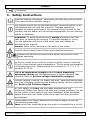
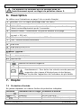
2. Used Symbols
This symbol indicates: Read instructions.
Not reading the instructions and manual can lead to damage,
injury or death.
This symbol indicates: Danger.
A hazardous condition or action that may result in injury or death.
This symbol indicates: Risk of danger/damage.
Risk of a hazardous condition or action that may result in damage,
injury or death.
This symbol indicates: Attention; important information.
Ignoring this information can lead to hazardous situations.
AC (Alternating Current)
DC (Direct Current)
Both AC and DC
Double insulation (class II-protection)
Earth
Fuse
Resettable fuse
Diode

DVM630
V. 01 – 22/04/2013 4 ©Velleman Inc.
Continuity
3. Safety Instructions
Read this manual thoroughly. Familiarize yourself with the functions
of the device before actually using it.
Only use the device for its intended purpose. Using the device in an
unauthorized way will void the warranty. Damage caused by
disregard of certain guidelines in this manual is not covered by the
warranty and the dealer will not accept responsibility for any ensuing
defects or problems.
WARNING: To avoid electrical shock always disconnect the test
leads prior to opening the housing. To prevent damage or injury,
only use batteries and fuses of the same type and ratings as
specified in this manual.
Remark: Refer to the warning on the back of the meter.
Keep the device away from children and unauthorized users.
Protect this device from shocks and abuse. Avoid brute force
when operating.
Avoid humidity, cold, heat, and large temperature fluctuations. When
the unit is moved from a cold to a warm location, leave it switched
off until it has reached room temperature. This to avoid condensation
and measuring errors. Ideal working environment is 73 °F ± 2 °F,
humidity 45-75 %.
This is an installation category CAT II 600V measuring
instrument. Never use this equipment in a higher category than
indicated. Refer to §4 Overvoltage/installation category.
Pollution degree 2 device. For indoor use only. Keep this device away
from rain, moisture, splashing and dripping liquids. Not for industrial
use. Refer to §5 Pollution degree.
For your safety, use only the test leads supplied with the
instrument. Before use, check that they are in good condition. Do not
use the meter or test leads if they look damaged. When damaged,
replace them with test leads of the same type and with the same
specifications.
Always place your fingers behind the protective edges of the test
probes while measuring!
Never touch free terminals when the meter is connected to a circuit.

DVM630
V. 01 – 22/04/2013 5 ©Velleman Inc.
Use the correct input terminals, function, and range for your
measurements. When the range of the value to be measured is
unknown, check that the range initially set on the meter is the
highest possible.
To avoid damages to the instrument, do not exceed the maximum
limits of the input values as shown in the technical specifications
tables.
Risk of electric shock during operation. Be very careful when
measuring live circuits. Use extreme caution when measuring
voltages higher than 60 VDC or 30 VAC rms.
Never connect the test leads to a voltage source if the rotary switch
is in the current, resistance, diode, transistor, or continuity mode.
This may damage the meter.
Disconnect circuit power and discharge all high-voltage capacitors
before testing resistance, continuity, capacitance or diodes. For
transistor tests, use the included transistor socket.
In TV repair work or when carrying out measurements on power
switching circuits, remember that high-amplitude voltage pulses at
the test points can damage the meter. Use of a TV filter will
attenuate any such pulses.
Do not replace internal parts yourself. Replace damaged or lost
accessories by identical ones with the same specifications. Order
spare accessories, e.g. test leads, from your dealer.
Switch off the meter and remove test probes prior to replacing the
battery or fuses.
All modifications of the device are forbidden for safety reasons.
Damage caused by user modifications to the device is not covered by
the warranty.
If the meter is used near a source of electromagnetic interference, the
display may become unstable or may indicate large errors.
Use the meter only as specified in this manual; otherwise, the
protection provided by the meter may be impaired.
Use extreme caution when working around bare conductors or bus bars.
Do not operate the meter near explosive gases, vapor, or dust.
Verify the meter‟s operation by measuring a known voltage. Do not use
the meter if it operates abnormally. Protection may be impaired. When
in doubt, have the meter serviced by a qualified technician. Make sure
the device cannot be used until it is repaired.
When making connections, connect the common test lead (black) before
connecting the live test lead (red). When disconnecting, disconnect the
live test lead (red) before disconnecting the common test lead (black).

DVM630
V. 01 – 22/04/2013 6 ©Velleman Inc.
Before changing functions or measuring range, disconnect the test leads
from the circuit under test.
For all DC functions, to avoid the risk of shock due to possible improper
readings, verify the presence of any AC voltages first by using the
AC function. Then select a DC voltage range equal to or greater than
the AC range.
Use 2 x 1.5 V AAA type batteries, properly installed in the meter‟s
battery case, to power the meter.
Replace the battery as soon as the battery indicator appears. With
a low battery, the meter may produce false readings that can lead to
electric shock and personal injury.
Do not operate the meter with the case (or part of the case) removed.
Always verify that all connections are reliable and safe.
Avoid body contact with ground potential (e.g. metallic terminals,
output sockets, lead clamp…) while measuring. Make sure to be
electrically insulated from ground during measurement.
4. Overvoltage/Installation Category
DMMs are categorized depending on the risk and severity of transient
overvoltage that might occur at the point of test. Transients are short-lived
bursts of energy induced in a system, e.g. caused by lightning strike on a
power line.
The existing categories according EN 61010-1 are:
CAT I
A CAT I-rated meter is suitable for measurements on protected
electronic circuits that are not directly connected to mains power,
e.g. electronics circuits, control signals…
CAT II
A CAT II-rated meter is suitable for measurements in CAT I
environments and mono-phase appliances that are connected to
the mains by means of a plug and circuits in a normal domestic
environment, provided that the circuit is at least 33 ft (10 m) apart
from a CAT III, or 66 ft (20 m) apart from a CAT IV environment.
E.g. household appliances, portable tools…
CAT III
A CAT III-rated meter is suitable for measurements in CAT I and
CAT II environments, as well as for measurements on (fixed)
mono- or poly-phased appliances which are at least 33 ft (10 m)
apart from a CAT IV environment, and for measurements in or on
distribution level equipment (fuse boxes, lighting circuits, electric
ovens).
CAT IV
A CAT IV-rated meter is suitable for measuring in CAT I, CAT II
and CAT III environments as well as on the primary supply level.
Note that for all measurements on equipment for which the supply
cables run outdoors (either overhead or underground) a CAT IV
meter must be used.

DVM630
V. 01 – 22/04/2013 7 ©Velleman Inc.
Warning: This device was designed in accordance with EN 61010-1
installation category CAT II 600V. This implies that certain restrictions in use
apply that are related to voltages and voltage peaks which can occur within
the environment of use. Refer to the table above.
This device is suitable for measurements up to 600 V on:
protected electronic circuits that are not directly connected to mains
power, e.g. electronics circuits, control signals, circuits behind isolating
transformer…
circuits that are directly connected to mains power, but limited to:
o measurements on mono-phase appliances that are connected to the
mains by means of a plug
o mono-phase appliances and circuits directly connected to the mains
in a normal domestic environment, provided that the circuit is at
least 33 ft apart from a CAT III, or 66 ft (20 m) apart from a CAT IV
environment. E.g. household appliances, portable tools, light circuits
at more than 33 ft (10 m) from a distribution board…
This device is NOT suitable for:
voltages above 600 V
measurements in/on low-voltage distribution boards (distribution boards
behind meter box)
measurements on (fixed) mono- or poly-phased appliances and circuits
in CAT III/CAT IV environments (e.g. mains outlets, electric ovens,
lighting circuits, bus bars, low-voltage distribution boards and circuit
breakers).
measurements on distribution equipment and outdoor installations
including meter boxes and equipment/circuits outside or remote from
the domestic environment e.g. circuits in sheds, garden houses and
free-standing garages, or circuits using underground wiring e.g. garden
lighting, pool-pump…
This device is only suitable for measurements up to 600 V in CAT II
environments.
5. Pollution Degree
IEC 61010-1 specifies different types of pollution environments, for which
different protective measures are necessary to ensure safety. Harsher
environments require more protection, and the protection against the
pollution which is to be found in a certain environment depends mainly on
the insulation and the enclosure properties. The pollution degree rating of
the DMM indicates in which environment the device may be used.
Pollution
degree 1
No pollution or only dry, nonconductive pollution occurs. The
pollution has no influence (only to be found in hermetically
sealed enclosures).

DVM630
V. 01 – 22/04/2013 8 ©Velleman Inc.
Pollution
degree 2
Only nonconductive pollution occurs. Occasionally, temporary
conductivity caused by condensation is to be expected (home
and office environments fall under this category).
Pollution
degree 3
Conductive pollution occurs, or dry nonconductive pollution
occurs that becomes conductive due to condensation that is to be
expected (industrial environments and environments exposed to
outside air - but not in contact with precipitation).
Pollution
degree 4
The pollution generates persistent conductivity caused by
conductive dust or by rain or snow (exposed outdoor
environments and environments where high humidity levels or
high concentrations of fine particles occur).
Warning: This device was designed in accordance with EN 61010-1
pollution degree 2. This implies that certain restrictions in use apply that
are related to pollution which can occur within the environment of use. Refer
to the table above.
This device is only suitable for measurements in Pollution
degree class 2 environments.
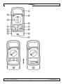
6. Overview
Refer to the illustrations on page 2 of this manual.
1
LCD display, 3 full digits and 1 half (max. range 1999)
2
HOLD: to lock the current reading
3
BACKLIGHT: press to switch on the display backlight. The backlight
switches off automatically after 3 seconds.
4
Rotary switch: to select type of measurement and range
5
VΩmAhFE: input terminal for all measurements except current
measurements > 200 mA
6
10A: input terminal for currents > 200 mA
7
COM: common input terminal
For cable testing:
8
USB jack
9
8P8C (RJ45)/RJ12/RJ11 jack
10
cable test lights
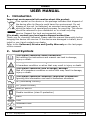
Remote cable test unit:
11
USB jack
12
8P8C (RJ45)/RJ12/RJ11 jack
13
cable test lights

DVM630
V. 01 – 22/04/2013 9 ©Velleman Inc.
Display:
Indicates negative reading.
H
The meter is in data hold mode.
The battery is low.
Warning: To avoid false readings, which can possibly
lead to electric shocks or personal injury, replace the
battery as soon as the battery indicator appears.
1
Over range.
7. Use
7.1 Input Protection
Never exceed the limit value for protection.
Function
Red lead connection
Input protection
200 mV
VΩmAhFE
220 VAC
V & V
VΩmAhFE
600 VDC or VAC
mA
VΩmAhFE
fuse 200mA/600V (resettable)
A
10A
fuse 10A/600V (fast)
measurement during max. 10 s
VΩmAhFE
220 V rms (15 s)
VΩmAhFE
250 VDC or 250 VAC rms
VΩmAhFE
250 VDC or 250 VAC rms
7.2 Switching On and Off
To switch the meter on, set the rotary switch [4] in the desired
measurement range position.
To switch the meter off, set the rotary switch to the OFF position.
Note: This device does not switch off automatically. To preserve the
battery, always set the rotary switch in the OFF position when the device is
not in use.
7.3 Data Hold Mode
The data hold mode locks the current readout on the display. Press the
HOLD key [2] to enter data hold mode. The display shows “H”. Press the
HOLD key again to return to normal measuring mode.

DVM630
V. 01 – 22/04/2013 10 ©Velleman Inc.
7.4 Measuring AC/DC Voltage
To avoid electrical shock and/or damage to the instrument, do not
attempt to measure voltages exceeding 600 VDC or 600 VAC rms.
To avoid electrical shock and/or damage to the instrument, do not
apply more than 600 VDC or 600 VAC rms between the COM
terminal and the earth ground.
DC voltage measuring range: 200.0 mV, 2.000 V, 20.00 V, 200.0 V, 600 V.
AC voltage measuring range: 200.0 V, 600 V.
To measure AC or DC voltages:
1. Select the appropriate V (DC voltage) or V (AC voltage) range with
the rotary switch.
2. Connect the black test lead to the “COM” socket and the red test lead to
the “VΩmAhFE” socket.
3. Connect the test probes in parallel to the circuit under test.
The measured value appears on the display. For DC measurements: if a
negative polarity is present at the red test probe, the indicated value is
preceded by a “–” sign.
Notes:
If the measured voltage exceeds the selected range, the display
shows “1”. Select a higher range.
The displayed value may be unstable in the lower ranges, even without
input or without connecting the test probes. In this case, hold the tips
of the test probes together and make sure the meter displays zero;
then measure again.
7.5 Measuring DC Current
To avoid electrical shock and/or damage to the instrument,
disconnect the circuit power and discharge all high-voltage
capacitors before measuring current.
To avoid damage to the meter, check the meter‟s fuse before
proceeding. Use the proper terminals, function and range for your
measurement. Never place the test probes in parallel with a circuit or
component when the leads are plugged into the current terminals.
In the 10 A range, measure current for maximum 10 seconds, then
wait for 15 minutes before the next measurement.
The meter‟s ranges are: 2.000 mA, 20.00 mA, 200.0 mA, 10.00 A.
To measure current:
1. Cut off the power supply of the circuit to measure.
2. Discharge all the high-voltage capacitors.
3. Select the appropriate A (DC) range with the rotary switch.
4. Connect the black test lead to the “COM” socket and the red test lead to
the “VΩmAhFE” socket for measurements of max. 200 mA. For a
maximum of 10 A, move the red test lead to the “10A” socket. If the

DVM630
V. 01 – 22/04/2013 11 ©Velleman Inc.
current to be measured is unknown beforehand, connect the red test
lead to the “10A” socket and set the range switch in the highest range
position. Then reduce gradually until the ideal resolution is obtained.
5. Break the circuit path to be tested.
6. Connect the black test probe to the more negative side of the break;
connect the red test probe to the more positive side of the break
(connection in series). Reversing the probes will give a negative
reading, but will not damage the meter.
7. Switch on the power supply of the circuit to measure.
The measured value appears on the display. For DC measurements,
when a negative polarity is present at the red test probe, the indicated
value is preceded by a “–” sign. When the measured value is higher
than the selected range limit, the display shows “1”. Select a higher
range.
8. Cut off the power supply of the circuit to measure.
9. Discharge all the high-voltage capacitors.
10. Remove the test probes from the circuit.
11. Restore the circuit to its original condition.
7.6 Measuring Resistance
To avoid electrical shock and/or damage to the instrument,
disconnect the circuit power and discharge all high-voltage capacitors
before measuring resistance.
Never perform resistance measurements on a live circuit.
The meter‟s ranges are: 200.0Ω, 2.000 kΩ, 20.00 kΩ, 200.0 kΩ, 2.000 MΩ.
To measure resistance:
1. Select the appropriate “ ” range with the rotary switch.
2. Connect the black test lead to the “COM” socket and the red test lead to
the “VΩmAhFE” socket.
3. Connect the test probes to the circuit/component under test.
The measured value appears on the display.
Notes:
The measured value of a resistor in a circuit often differs from the
resistor‟s rated value. This is because the meter‟s test current flows
through all possible paths between the probe tips.
To increase accuracy when measuring low resistance values, first hold
the tips of the test probes together to determine the resistance value of
the test leads. Subtract this value from the measured value of the
circuit.
If the measured resistance exceeds the selected range or in case of an
open circuit, the display shows “1”.

DVM630
V. 01 – 22/04/2013 12 ©Velleman Inc.
7.7 Testing Diodes
To avoid electrical shock and/or damage to the instrument,
disconnect the circuit power and discharge all high-voltage capacitors
before testing diodes.
Never perform diode measurements on a live circuit.
To test a diode out of a circuit:
1. Set the rotary switch to the position.
2. Connect the black test lead to the “COM” socket and the red test lead to
the “VΩmAhFE” socket.
3. Connect the black test probe to the cathode (negative); connect the red
test probe to the anode (positive) of the diode.
The meter displays the approximate forward voltage drop. If the probe
connection is reversed, the meter displays “1”.
Notes:
Measuring diodes that are part of a circuit might produce faulty results.
Consider disconnecting them from the circuit.
In a circuit, a good diode should produce a forward bias reading of 0.5 V
to 0.8 V. However, the reverse bias reading can vary depending on the
resistance of other pathways between the probe tips.
7.8 Audible Continuity Test
To avoid electrical shock and/or damage to the instrument,
disconnect the circuit power and discharge all high-voltage capacitors
before testing the continuity.
Never perform continuity tests on a live circuit.
To test for continuity:
1. Set the rotary switch to the position.
2. Connect the black test lead to the “COM” socket and the red test lead to
the “VΩmAhFE” socket.
3. Connect the test probes to the circuit/component under test.
If the measured resistance is less than ± 100 Ω, the buzzer sounds
continuously and the resistance is displayed. If the measured resistance
exceeds 2 kΩ or in case of an open circuit, the display shows “1”.
7.9 Transistor Test (hFE)
To avoid electrical shock and/or damage to the instrument, do not
apply more than 250 VDC or 250 VAC rms between the COM
terminal and the “VΩmAhFE” terminal.
Use the included adaptor socket.

DVM630
V. 01 – 22/04/2013 13 ©Velleman Inc.
To measure a transistor:
1. Set the rotary switch to the “hFE” position.
2. Connect the black test lead to the “COM” socket and the red test lead to
the “VΩmAhFE” socket.
3. Connect the test probes to the transistor adapter socket with correct
polarity: the “COM” probe (black) goes into the “COM” socket of the
adapter; the red probe goes into the other socket. Push the probes into
the adapter as far as they go.
4. Determine whether the transistor is of the NPN or PNP type and locate
the emitter, the base and the collector. Insert the leads into the proper
holes in the included adaptor socket.
The display shows the approximate hFE-value (current gain).
7.10 Cable Test
Never use the tester on live wires; this will damage the tester.
Use the DMM with the remote cable unit tester for testing network or
telephone cables (RJ45 (8P8C), RJ12 (6P6C), RJ11 (6P4C)) and USB cables.
1. Slide the terminal cover into the upper position (see illustration on
page 2).
2. Set the rotary switch to the “AUTO” position.
3. Plug in the cable to be tested as follows:
o USB cable: plug one end into the USB jack [8] on the DMM; plug the
other end into the USB jack [11] of the remote unit.
o Twisted pair: plug one end into the jack [9] on the DMM; plug the
other end into the jack [12] of the remote unit.
The cable test lights on the DMM [10] and on the remote unit [13] light up
in sequence.
You can interpret the cable test lights as follows:
Description
Sequence
Good connection: all indicators
light up in sequence.
Notes: Indicator G lights up only
for cables with a ground (GND). For
RJ11 cables, the lights on the
remote light up in reverse
sequence.
DMM:
1 2 3 4 5 6 7 8 G (8P8C)
remote:
1 2 3 4 5 6 7 8 G (8P8C)
DMM:
2 3 4 5 6 7 (RJ12/6P6C)
remote:
2 3 4 5 6 7 (RJ12/6P6C)
DMM:
3 4 5 6 (RJ11/6P4C)
remote:
6 5 4 3 (RJ11/6P4C)
DMM:
1 2 3 4 (USB)
remote:
1 2 3 4 (USB)
Open circuit: wire 2 is broken;
indicator 2 does not light up on
DMM and remote.
DMM:
1 2 3 4 5 6 7 8
remote:
1 2 3 4 5 6 7 8

DVM630
V. 01 – 22/04/2013 14 ©Velleman Inc.
Description
Sequence
Open circuits: wires 2 and 5 are
broken; indicators 2 and 5 do not
light up on master and remote.
DMM:
1 2 3 4 5 6 7 8
remote:
1 2 3 4 5 6 7 8
Short-circuit between wires 2
and 4: all indicators on DMM light
up in sequence, indicators 2 and 4
do not light up on remote.
DMM:
1 2 3 4 5 6 7 8
remote:
1 2 3 4 5 6 7 8
If wires are misconnected or reversed: the indicators on the DMM light up in
sequence; the indicators on the remote don‟t.
4. After testing, remove the cable from DMM and cable test unit and set
the rotary switch in the OFF position.
8. Cleaning and Maintenance
Instructions for Safe Maintenance
Meter calibration, maintenance, repair, and other operations can only be
performed by technicians who fully understand the meter and electrical
shock hazards. Do not attempt to repair or service the meter unless you
are qualified to do so and have the relevant calibration, performance
test and service information.
When performing meter maintenance, only use specified and approved
replacement parts.
Before opening the meter, disconnect all power supplies and make sure
that you have no static electricity to avoid damaging the meter
components.
Be aware that there may be dangerous voltages remaining in some
capacitors in the meter even after powering off.
WARNING: To avoid electrical shock, always disconnect the test
leads before opening the housing. To prevent fire hazards, install
fuses with the exact same specifications. To avoid electrical shock
and/or damage to the instrument, do not get water inside the
housing.
Remark: refer to the warning on the back of the meter.
Do not replace internal parts yourself. Replace damaged or lost
accessories by identical ones with the same specifications. Order
spare accessories, e.g. test leads, from your dealer.
Switch off the meter and remove test leads prior to replacing the
battery or fuses.

DVM630
V. 01 – 22/04/2013 15 ©Velleman Inc.
General Maintenance
Wipe the device regularly with a moist, lint-free cloth and a small amount of
detergent. Do not use alcohol, solvents or abrasive products.
Dirty or wet input sockets may affect the readings. To clean the input
sockets:
1. Switch off the meter.
2. Remove the test probes from the circuit under test. Remove all test
leads from the input sockets.
3. Gently remove any dirt that may be in the sockets.
4. Soak a new cotton bud with isopropyl alcohol and work around the
inside of each socket.
5. Use a new cotton bud to apply a light coating of machine oil to the
inside of each socket.
6. Make sure the sockets are perfectly clean and dry before using the
meter again.
Battery Replacement
Low/bad batteries can produce false readings, which can possibly
lead to electric shocks or personal injury. Therefore, you must
replace the battery as soon as the battery indicator appears.
Use only batteries of the specified type and rating (AAA, 1.5 V).
To avoid shock or personal injury, before opening the battery cover,
always turn off the meter and disconnect the test leads.
Do not puncture batteries or throw them in fire as they may explode.
Do not attempt to recharge non-rechargeable batteries (alkaline).
Dispose of batteries in accordance with local regulations. Keep
batteries away from children.
1. Switch off the meter.
2. Remove the test probes from the circuit under test. Remove the test
leads from the input sockets.
3. Remove the protective cover, and unscrew the battery cover at the back
of the meter.
4. Replace the batteries (AAA, 1.5 V). Do not use rechargeable batteries
and respect the polarity.
5. Close the battery cover and tighten the screw.
Fuse Replacement
Use only fuses of the specified type, ratings, and speed
(200mA/600V resettable; 10A/600V fast). The fuse rarely needs to
be replaced and a blown fuse is almost always caused by a human
error.
To avoid shock or personal injury, before opening the housing,
always turn off the meter and disconnect the test leads.

DVM630
V. 01 – 22/04/2013 16 ©Velleman Inc.
1. Switch off the meter.
2. Remove the test probes from the circuit under test. Remove the test
leads from the input sockets.
3. Remove the protective cover, and remove the batteries.
4. Unscrew the screws at the back of the meter and gently open the
housing.
5. Replace the blown fuse with a fuse of the same type and rating.
6. Close the housing and tighten the screws.
7. Place the battery back and close the battery cover.
8. Put the protective cover back.
Storage
Remove the batteries from the device if it will not be used for a long time.
Old batteries can begin to leak and damage the device.
Do not store the device in a high temperature or high humidity
environment.
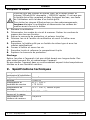
9. Technical Specifications
overvoltage/installation
category
CAT II 600V
pollution degree
class 2
altitude
< 6500 ft
operating temperature
and humidity
32 °F - 104 °F
< 75 % RH
storage temperature
14 °F - 140 °F, remove battery
max. voltage between
probe and ground
600 VDC or VAC
test leads specification
10A/600V
fuse protection
fuse 1: 200mA/600V
fuse 2: 10A/600V
mA terminal fuse: 200mA/600V (resettable)
10A terminal fuse: Ø 0.197" x 0.787"
(Ø 5 x 20 mm) 10A/600V (fast)
display
3½ digit LCD with automatic indication of functions
and symbols
maximum display
1999
LCD display size
1.8" x 0.7"
ranging mode
manual
over range indication
yes, “1”
low battery indication
yes,
polarity indication
“–” displayed automatically
data hold
yes
automatic power-off
no

DVM630
V. 01 – 22/04/2013 17 ©Velleman Inc.
power supply
2 x AAA 1.5 V R03P SUM4 battery (incl.)
dimensions
6.4" x 2.9" x 1.5"
weight
8.96 oz (including battery)
accessories
user manual, test leads, holster, batteries, adapter
for transistor measurements, cable test unit
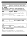
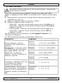
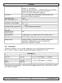
9.1 Accuracy
Accuracy is specified for a period of one year after calibration and at an
ambient temperature from 64 °F to 82 °F, with relative humidity < 75 %.
DC voltage
Range
Resolution
Accuracy
200 mV
100 µV
± (0.5 % of reading + 2 digits)
2 V
1 mV
± (0.8 % of reading + 2 digits)
20 V
10 mV
200 V
100 mV
600 V
1 V
± (1.0 % of reading + 2 digits)
Overload protection: 220 VAC for 200 mV range; 600 VDC or VAC for other
ranges.
AC voltage
Range
Resolution
Accuracy
200 V
100 mV
± (1.2 % of reading + 10 digits)
600 V
1 V
± (1.2 % of reading + 10 digits)
Overload protection: 600 VDC or VAC for all ranges.
Frequency response: 45 Hz – 450 Hz.
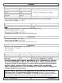
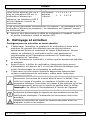
DC current
Range
Resolution
Accuracy
2 mA
1 µA
± (1.0 % of reading + 2 digits)
20 mA
10 µA
200 mA
100 µA
± (1.2 % of reading + 2 digits)
10 A
10 mA
± (2.0 % of reading + 2 digits)
Overload protection:
fuse 1: 200mA/600V (resettable)
fuse 2: 10A/600V (fast).
Measurement voltage drop: 200 mV.
When measuring currents up to 10 A, max. 10 seconds continuous
measurement followed by a 15 minutes break between 2 measurements.

DVM630
V. 01 – 22/04/2013 18 ©Velleman Inc.
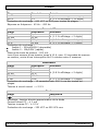
Resistance
Range
Resolution
Accuracy
200 Ω
100 mΩ
± (0.8 % of reading + 2 digits)
2 kΩ
1 Ω
20 kΩ
10 Ω
200 kΩ
100 Ω
2 MΩ
1 kΩ
± (1.0 % of reading + 2 digits)
Overload protection: 15 seconds maximum 220 V rms on all ranges.
Open circuit voltage: < 2.5 V
Diode
Range
Resolution
1 mV
Display: approximation of diode forward voltage drop
Forward DC current: ± 1 mA
Reversed DC voltage: ± 2.5 V
Overload protection: 250 VDC or 250 VAC rms
Continuity
Continuity beeper: ≤ 100 Ω
Open circuit voltage: ± 2.5 V
Overload protection: 250 VDC or 250 VAC rms
Transistor
Display: hFE approximation (0-1000)
Base current: ± 10 µA
Vce: ± 2.8 V
Over range indication
Range
Resolution
Accuracy
600 VDC
1 V
± (0.5 % of reading + 5 digits)
600 VAC
1 V
± (0.5 % of reading + 1 digits)
Use this device with original accessories only. Velleman Inc. cannot
be held responsible in the event of damage or injury resulting from
(incorrect) use of this device. For more info concerning this product
and the latest version of this manual, please visit our website
www.vellemanusa.com. The information in this manual is subject to
change without prior notice.
© COPYRIGHT NOTICE – The copyright to this manual is owned by
Velleman Inc. All worldwide rights reserved. No part of this manual
may be copied, reproduced, translated or reduced to any electronic medium
or otherwise without the prior written consent of the copyright holder.

DVM630
V. 01 – 22/04/2013 19 ©Velleman Inc.
MODE D'EMPLOI
1. Introduction
Des informations environnementales importantes concernant ce
produit Ce symbole sur l'appareil ou l'emballage indique que l‟élimination
d‟un appareil en fin de vie peut polluer l'environnement. Ne pas
jeter un appareil électrique ou électronique (et des piles
éventuelles) parmi les déchets municipaux non sujets au tri
sélectif ; une déchèterie traitera l‟appareil en question. Renvoyer
cet appareil à votre fournisseur ou à un service de recyclage local.
Il convient de respecter la réglementation locale relative à la protection de
l‟environnement.
En cas de questions, contacter les autorités locales pour élimination.
Nous vous remercions de votre achat ! Lire la présente notice attentivement
avant la mise en service de l‟appareil. Si l‟appareil a été endommagé
pendant le transport, ne pas l‟installer et consulter votre revendeur.
Se référer à la garantie de service et de qualité Velleman® en fin de
notice.
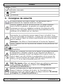
2. Symboles utilisés
Ce symbole indique : Lire les instructions.
Ne pas lire les instructions ou la notice peut causer des
endommagements ou blessures, ou entraîner la mort.
Ce symbole indique : Danger.
Une situation ou action dangereuse pouvant causer des blessures
ou entraîner la mort.
Ce symbole indique : Risque de danger/d’endommagement.
Risque d‟une situation dangereuse ou action pouvant causer des
endommagements ou blessures, ou entraîner la mort.
Ce symbole indique : Attention ; information importante.
La négligence de cette information peut engendrer une situation
dangereuse.
AC (« alternating current » ou courant alternatif)
DC (« direct current » ou courant continu)
CA et CC
Double isolation (classe de protection II)
Terre

DVM630
V. 01 – 22/04/2013 20 ©Velleman Inc.
Fusible
Fusible réarmable
Diode
Continuité
3. Consignes de sécurité
Lire attentivement ce mode d'emploi. Se familiariser avec le
fonctionnement de l‟appareil avant de l‟utiliser.
N‟utiliser l'appareil qu‟à sa fonction prévue. Un usage impropre
annule d'office la garantie. La garantie ne s‟applique pas aux
dommages survenus en négligeant certaines directives de cette
notice et votre revendeur déclinera toute responsabilité pour les
problèmes et les défauts qui en résultent.
AVERTISSEMENT : Pour éviter les chocs électriques, toujours
déconnecter les cordons de mesure avant d'ouvrir le boîtier. Pour
éviter des dommages ou blessures, n'utiliser que des piles et fusibles
du même type et ayant les mêmes spécifications que celles décrites
dans ce manuel.
Remarque : Se référer à l‟avertissement à l‟arrière de l‟appareil.
Garder l'appareil hors de la portée des enfants et des personnes non
autorisées.
Protéger l‟appareil des chocs. Traiter avec circonspection pendant
l‟opération.
Protéger de l'humidité, du froid, de la chaleur et des larges variations
de température. Attendre jusqu‟à ce que l‟appareil ait atteint la
température ambiante lorsqu‟il est déplacé d‟un endroit froid à un
endroit chaud, ceci afin d‟éviter la condensation et les erreurs de
mesure. L'environnement de travail idéal est une température de
73 °F ± 2 °F et un taux d'humidité entre 45-75 %.
Cet appareil correspond à la catégorie de surtension CAT II
600V. Ne jamais utiliser cet appareil dans une catégorie supérieure
à celle indiquée. Se référer au chapitre 4 « Catégories de
surtension/d’installation ».
Appareil correspondant au degré de pollution 2. Uniquement pour
usage à l‟intérieur. Protéger de la pluie, de l‟humidité et des
projections d‟eau. Ne convient pas à un usage industriel. Se référer
au chapitre 5 « Degré de pollution ».
La page est en cours de chargement...
La page est en cours de chargement...
La page est en cours de chargement...
La page est en cours de chargement...
La page est en cours de chargement...
La page est en cours de chargement...
La page est en cours de chargement...
La page est en cours de chargement...
La page est en cours de chargement...
La page est en cours de chargement...
La page est en cours de chargement...
La page est en cours de chargement...
La page est en cours de chargement...
La page est en cours de chargement...
La page est en cours de chargement...
La page est en cours de chargement...
La page est en cours de chargement...
La page est en cours de chargement...
La page est en cours de chargement...
La page est en cours de chargement...
La page est en cours de chargement...
La page est en cours de chargement...
La page est en cours de chargement...
La page est en cours de chargement...
La page est en cours de chargement...
La page est en cours de chargement...
La page est en cours de chargement...
La page est en cours de chargement...
La page est en cours de chargement...
La page est en cours de chargement...
La page est en cours de chargement...
La page est en cours de chargement...
La page est en cours de chargement...
La page est en cours de chargement...
La page est en cours de chargement...
La page est en cours de chargement...
-
 1
1
-
 2
2
-
 3
3
-
 4
4
-
 5
5
-
 6
6
-
 7
7
-
 8
8
-
 9
9
-
 10
10
-
 11
11
-
 12
12
-
 13
13
-
 14
14
-
 15
15
-
 16
16
-
 17
17
-
 18
18
-
 19
19
-
 20
20
-
 21
21
-
 22
22
-
 23
23
-
 24
24
-
 25
25
-
 26
26
-
 27
27
-
 28
28
-
 29
29
-
 30
30
-
 31
31
-
 32
32
-
 33
33
-
 34
34
-
 35
35
-
 36
36
-
 37
37
-
 38
38
-
 39
39
-
 40
40
-
 41
41
-
 42
42
-
 43
43
-
 44
44
-
 45
45
-
 46
46
-
 47
47
-
 48
48
-
 49
49
-
 50
50
-
 51
51
-
 52
52
-
 53
53
-
 54
54
-
 55
55
-
 56
56


Velleman DVM630 Manuel utilisateur
- Catégorie
- Multimètres
- Taper
- Manuel utilisateur
dans d''autres langues
- English: Velleman DVM630 User manual
- español: Velleman DVM630 Manual de usuario
Documents connexes
-
Velleman DVM 68 Manuel utilisateur
-
Velleman DVM4x00 Series Manuel utilisateur
-
-
-
Velleman DVM4200 Manuel utilisateur
-
-
Velleman DCM120 Manuel utilisateur
-
-
Velleman DVM93 spécification