Continental Fireplaces CDI3NE Le manuel du propriétaire
- Catégorie
- Cheminées
- Taper
- Le manuel du propriétaire

FRENCH
PG. 45
W415-2801 / 01.21.20
ADD MANUAL TITLE
Wolf Steel Ltd., 24 Napoleon Rd., Barrie, ON, L4M 0G8 Canada / 103 Miller Drive, Crittenden, Kentucky, USA, 41030
Phone 1 (866) 820-8686 • www.continentalfi replaces.com • hearth@continentalfi replaces.com
CERTIFIED TO THE CANADIAN AND AMERICAN NATIONAL STANDARDS:
CSA 2.22 AND ANSI Z21.50 FOR VENTED DECORATIVE GAS APPLIANCES
INSTALLER:
Leave this manual with the appliance
CONSUMER:
Retain this manual for future reference
ADD PRODUCT CODE HERE (TRADE GOTHIC LT STD FONT)
NATURAL GAS MODELS:
PROPANE GAS MODELS:
Product Name / Code
(MUST use title from Price Book)
ADD ____ ILLUSTRATED
ADD PRODUCT IMAGE
CSA /
INTERTEK
LOGO
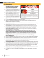
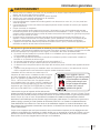
SAFETY INFORMATION
- Do not store or use gasoline or other
fl ammable vapors and liquids in the vicinity of
this or any other appliance.
- WHAT TO DO IF YOU SMELL GAS:
• Do not try to light any appliance.
• Do not touch any electrical switch; do not
use any phone in your building.
• Immediately call your gas supplier from a
neighbour’s phone. Follow the gas
supplier’s instructions.
• If you cannot reach your gas supplier, call
the fi re department.
- Installation and service must be performed
by a qualifi ed installer, service agency, or the
supplier.
This appliance may be installed in an aftermarket,
permanently located, manufactured home (USA
only) or mobile home, where not prohibited by
local codes.
This appliance is only for use with the type of gas
indicated on the rating plate. This appliance is
not convertible for use with other gases, unless
a certifi ed kit is used.
FIRE OR EXPLOSION HAZARD
Failure to follow safety warnings exactly
could result in serious injury, death, or
property damage.
WARNING
!
ENGLISH
$10.00
FOR INDOOR USE ONLY
IF INSTALLATION + OPERATION, ADD SERIAL
NUMBER LABEL HERE
IF SEPARATE MANUALS, ADD “PLACE
BARCODE LABEL ON THE OWNER’S MANUAL”
PLACE BARCODE LABEL ON THE
OWNER’S MANUAL
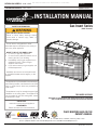
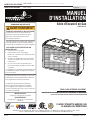
CDI3N / CDI3NE
CDI3P / CDI3PE
INSTALLATION MANUAL
Gas Insert Series
(CDI3E illustrated)
CERTIFIED TO THE CANADIAN AND AMERICAN NATIONAL STANDARDS:
CSA 2.33 AND ANSI Z21.88 FOR VENTED GAS FIREPLACE HEATERS
SAFETY BARRIER

W415-2801 / 01.21.20
EN
2
safety information
• This appliance is hot when operated and
can cause severe burns if contacted.
• Any changes or alterations to this
appliance or its controls can be
dangerous and is prohibited.
• Do not operate appliance before reading and
understanding operating instructions. Failure
to operate appliance according to operating
instructions could cause fi re or injury.
• Ensure the glass door is opened or removed
when lighting the pilot for the fi rst time and
when the gas supply has run out.
• Risk of fi re or asphyxiation, do not operate
appliance with fi xed glass removed and never
obstruct the front opening of the appliance.
• Do not connect 110 volts to the control valve,
with the exception of models; GSST8 and
GT8.
• Risk of burns. The appliance should be turned off and cooled before servicing.
• Do not install damaged, incomplete or substitute components.
• Risk of cuts and abrasions. Wear protective gloves, protective footwear, and safety glasses during
installation. Sheet metal edges may be sharp.
• Do not burn wood or other materials in this appliance.
• Provide adequate ventilation and combustion air. Provide adequate accessibility clearance for servicing
and operating the appliance.
• High pressure will damage valve. Disconnect gas supply piping before pressure testing gas line at
test pressures above 1/2 psig. Close the manual shut-off valve before pressure testing gas line at test
pressures equal to or less than 1/2 psig (35mb).
• The appliance must not be operated at temperatures below freezing (32°F / 0°C). Allow the appliance
to warm to above freezing prior to operation, with the exception of models; GSS36, GSS42; these
appliances are suitable for 0°F / -18°C.
• Children and adults should be alerted to hazards of high surface temperature and should stay
away to avoid burns or clothing ignition.
• Young children should be carefully supervised when they are in the same room as the
appliance. Toddlers, young children and others may be susceptible to accidental contact
burns. A physical barrier is recommended if there are at risk individuals in the house. To
restrict access to an appliance or stove, install an adjustable safety gate to keep toddlers,
young children and other at risk individuals out of the room and away from hot surfaces.
• Clothing or other fl ammable material should not be placed on or near the appliance.
• Due to high temperatures, the appliance should be located out of traffi c and away from
furniture and draperies.
• Furniture or other objects must be kept a minimum of 4 feet (1.22m) away from the front of the appliance.
• Ensure you have incorporated adequate safety measure to protect infants/toddlers from touching hot
surfaces.
• Even after the appliance is off, it will remain hot for an extended period of time.
• Check with your local hearth specialty dealer for safety screens and hearth guards to protect children
from hot surfaces. These screens and guards must be fastened to the fl oor.
• Any safety screen, guard or barrier removed for servicing the appliance, must be replaced prior
to operating the appliance.
• It is imperative that the control compartments, burners and circulating blower and its passageway in the
appliance and venting system are kept clean. The appliance and its venting system should be inspected
before use and at least annually by a qualifi ed service person. More frequent cleaning may be required
due to excessive lint from carpeting, bedding material, etc. The appliance area must be kept clear and
free from combustible materials, gasoline and other fl ammable vapors and liquids.
• If the appliance shuts off, do not re-light until you provide fresh air. If appliance keeps shutting off, have it
serviced. Keep burner and control compartment clean.
• Under no circumstances should this appliance be modifi ed.
• Do not allow wind or fans to blow directly into the appliance. Avoid any drafts that alter burner fl ame
patterns.
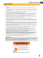
HOT GLASS WILL CAUSE
BURNS.
DO NOT TOUCH GLASS UNTIL
COOLED.
NEVER ALLOW CHILDREN TO
TOUCH GLASS.
!
DANGER
A barrier designed to reduce the risk of burns from the
hot viewing glass is provided with this appliance and
shall be installed for the protection of children and other
at-risk individuals.
!
WARNING

EN
W415-2801 / 01.21.20
3
safety information
!
WARNING
• Do not use a blower insert, heat exchanger insert or other accessory not approved for use with this
appliance.
• This appliance must not be connected to a chimney fl ue pipe serving a separate solid fuel burning
appliance.
• Do not use this appliance if any part has been under water. Immediately call a qualifi ed service technician
to inspect the appliance and to replace any part of the control system and any gas control which has
been under water.
• Do not operate the appliance with the glass door removed, cracked or broken. Replacement of the glass
should be done by a licensed or qualifi ed service person, if equipped.
• Do not strike or slam shut the appliance glass door, if equipped.
• Only doors / optional fronts certifi ed with the appliance are to be installed on the appliance.
• Keep the packaging material out of reach of children and dispose of the material in a safe manner. As
with all plastic bags, these are not toys and should be kept away from children and infants.
• Carbon or soot should not occur in a vent free appliance as it can distribute into the living area of your
home. If you notice any signs of carbon or soot, immediately turn off your appliance and arrange to have
it serviced by a qualifi ed technician before operating it again.
• If equipped, the screen must be in place (closed) when the appliance is in operation.
• When equipped with pressure relief doors, they must be kept closed while the appliance is operating
to prevent exhaust fumes containing carbon monoxide, from entering into the home. Temperatures of
the exhaust escaping through these openings can also cause the surrounding combustible materials to
overheat and catch fi re.
• Carbon monoxide poisoning may lead to death; early signs of carbon monoxide poisoning resemble the
fl u, with headache, dizziness and/or nausea. If you have these signs, the appliance may not be working
properly. Get fresh air at once! Have appliance serviced. Some people; pregnant women, persons with
heart or lung disease, anemia, those under the infl uence of alcohol, those at high altitudes are more
affected by carbon monoxide than others. Failure to keep the primary air opening(s) of the burner(s) clean
may result in sooting and property damage.
• As with any combustion appliance, we recommend having your appliance regularly inspected and
serviced as well as having a Carbon Monoxide Detector installed in the same area to defend you and
your family against Carbon Monoxide (not applicable for outdoor appliances).
• Ensure clearances to combustibles are maintained when building a mantel or shelves above the
appliance. Elevated temperatures on the wall or in the air above the appliance can cause melting,
discolouration or damage to decorations, a TV or other electronic components.
• For appliances equipped with a safety barrier; if the barrier becomes damaged, the barrier
shall be replaced with the manufacturer’s barrier for this appliance.
• Installation and repair should be done by a qualifi ed service person. It is imperative that control
compartments, burners and circulating air passageways of the appliance be kept clean.
• For outdoor products only: this appliance must not be installed indoors or within any structure that
prevents or inhibits the exhaust gases from dissipating in the outside atmosphere.
• If applicable, the millivolt version of this appliance uses and requires a fast acting thermocouple. Replace
only with a fast acting thermocouple supplied by Wolf Steel Ltd.
!
WARNING
!
Disconnect the appliance main gas valve/control
from the supply piping when pressure testing that
system at pressures in excess of 1/2 psi (3.5 kPa).
Isolate the appliance with it’s shut off valve during
any pressure testing of the supply piping at
pressures equal to or less than 1/2 psi (3.5 kPa).
FIRE RISK HAZARD / DELAYED IGNITION
High supply pressure will damage the valve / controls.
Add California Prop 65 warning
!
WARNING:
This product can expose you to chemicals including lead and lead compounds,
which are known to the State of California to cause cancer, and chemicals including carbon
monoxide, which are known to the State of California to cause birth defects or other reproduc-
tive harm. For more information, go to www.P65Warnings.ca.gov.

W415-2801 / 01.21.20
EN
4
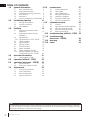
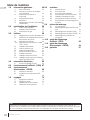
table of contents
The information throughout this manual is believed to be correct at the time of printing. Wolf Steel Ltd. reserves
the right to change or modify any information within this manual at any time without notice. Changes, other than
editorial are denoted by a vertical line in the margin.
note:
1.0 general information 5
1.1 rates and effi ciencies 5
1.2 rating plate information 7
1.3 operating and lighting instructions 8
1.4 shut-off valve 8
1.5 dimensions 9
1.6 minimum clearance to combustibles 9
2.0 installation planning 10
2.1 levelling the appliance 10
2.2 chimney connection 11
2.3 gas installation 12
3.0 finishing 13
3.1 minimum combustible mantel
clearances 13
3.2 safety barrier & door removal /
installation 14
3.3 log placement 15
3.3.1 log placement for CDI3 / CDI3E 15
3.4 media installation 18
3.5 logo placement 18
3.6 glowing embers 18
3.7 charcoal embers 19
3.8 battery installation 19
3.9 battery installation (CDI3E) 19
3.10 bracket installation for optional
F45/60 receiver (CDI3 / CDI3E) 20
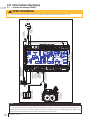
4.0 electrical information 21
4.1 wiring diagram (CDI3E) 21
5.0 operation (millivolt - CDI3) 22
6.0 operation (electronic - CDI3E) 23
6.1 pilot on demand 24
6.2 ACS switch location (CDI3E) 24
7.0 adjustments 25
7.1 pilot burner adjustment 25
7.2 venturi adjustment 25
7.3 fl ame characteristics 26
7.4 optional wall switch 26
8.0 maintenance 27
8.1 annual maintenance 28
8.2 care of glass 28
8.3 care of plated parts 29
8.4 door glass replacement 29
8.5 media tray installation 29
8.6 restricting vertical vents 30
8.7 valve train replacement 31
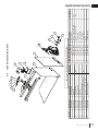
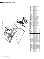
9.0 replacement parts 32
9.1 overview 33
9.2 right side access plate assembly 34
9.3 valve train assembly (CDI3) 35
9.4 valve train assembly (CDI3E) 36
9.5 fi rebox top assembly 37
10.0 troubleshooting (millivolt - CDI3) 38
11.0 troubleshooting
(electronic - CDI3E) 40
12.0 warranty 43
13.0 notes 44

EN
W415-2801 / 01.21.20
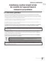
5
standard checklist
Installer: please fi ll out appliance checklist in the
owner’s manual.
When the appliance is installed at elevations above 4,500ft (1372m), and in the absence of specifi c recommendations
from the local authority having jurisdiction, the certifi ed high altitude input rating shall be reduced at the rate of 4% for each
additional 1,000ft (305m). Expansion / contraction noises during heating up and cooling down cycles are normal
and are to be expected.
This appliance is approved for bathroom, bedroom and bed-sitting room installations and is certifi ed for mobile
home installation.
This appliance is fi eld convertible between natural gas (NG) and propane (P). To convert from one to another,
consult your authorized dealer / distributor.
This appliance is only for use with the type of gas indicated on the rating plate. This appliance is not
convertible for use with other gases, unless a certifi ed kit is used.
The protective wrap on plated parts is best removed when the assembly is at room temperature but this can
be improved if the assembly is warmed, using a hair dryer or similar heat source. The protective wrap must be
removed before operating the appliance.
This appliance is a decorative product. It is not a source of heat and not intended to burn solid fuel.
note:
Batteries must be disposed of according to the local laws and regulations. Some batteries may be
recycled, and may be accepted for disposal at your local recycling center. Check with your
municipality for recycling instructions.
A barrier designed to reduce the risk of burns is provided with the appliance and must be installed. Never
operate the appliance without the barrier installed.
important:
Some components and/or media are packaged separately and must be installed in accordance with the
information in this manual.
1.0 general information
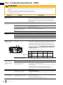
1.1 rates and effi ciencies
NG P
Altitude (FT) 0 - 4500
Max. Input (BTU/hr) 24,500
Max. Output (BTU/hr) 13,475
Min. Inlet Gas Supply Pressure 4.5" W.C. (11mb) 11" W.C. (27mb)
Max. Inlet Gas Supply Pressure 7" * W.C. (17mb) 13" W.C. (32mb)
Manifold Pressure (under Flow Conditions) 3.5 W.C. (9mb) 10" W.C. (25mb)
CDI3 / CDI3E
* Max. inlet pressure not to exceed 13".

W415-2801 / 01.21.20
EN
6
general information
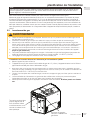
THIS GAS APPLIANCE MUST BE INSTALLED AND SERVICED BY A QUALIFIED INSTALLER to conform with local
codes. Installation practices vary from region to region and it is important to know the specifi cs that apply to your area, for
example in the state of Massachusetts:
• This product must be installed by a licensed plumber or gas fi tter when installed within the commonwealth of
Massachusetts.
• The appliance damper must be removed or welded in the open position prior to installation of an appliance insert or gas
log.
• The appliance off valve must be a “T” handle gas cock.
• The fl exible connector must not be longer than 36 inches (0.9m).
• A carbon monoxide detector is required in all rooms containing gas fi red appliances.
• The appliance is not approved for installation in a bedroom or bathroom unless the unit is a direct vent sealed
combustion product.
The installation must conform with local codes or, in absence of local
codes, the National Gas and Propane Installation Code CSA B149.1
in Canada, or the National Fuel Gas Code, ANSI Z223.1 / NFPA 54
in the United States. Suitable for mobile home installation if installed
in accordance with the current standard CAN/CSA Z240MH Series,
for gas equipped mobile homes, in Canada or ANSI Z223.1 and
NFPA 54 in the United States.
The appliance and its individual shutoff valve must be disconnected
from the gas supply piping system during any pressure testing
of that system at test pressures in excess of 1/2 psig (35 mb).
The appliance must be isolated from the gas supply piping system by closing its individual manual shutoff valve during any
pressure testing of the gas supply piping system at test pressures equal to or less than 1/2 psig (35 mb). When installed
with a blower or fan, the junction box must be electrically connected and grounded in accordance with local codes. In the
absence of local codes, use the current CSA C22.1 Canadian Electrical Code in Canada or the ANSI / NFPA 70 National
Electric Code in the United States. In the case where the blower is equipped with a power cord, it must be connected into a
properly grounded receptacle. The grounding prong must not be removed from the cord plug.
The following does not apply to inserts; as long as the required clearance to combustibles is maintained, the most desirable
and benefi cial location for an appliance is in the center of a building, thereby allowing the most effi cient use of the heat
created. The location of windows, doors and, the traffi c fl ow in the room where the appliance is to be located should be
considered. If possible, you should choose a location where the vent will pass through the house without cutting a fl oor or
roof joist. If the appliance is installed directly on carpeting, vinyl tile or other combustible material other than wood fl ooring, the
appliance shall be installed on a metal or wood panel extending the full width and depth, unless otherwise tested.
We suggest that our gas
hearth products be installed
and serviced by professionals
who are certied in the U.S.
by the National Fireplace
Institute
®
(NFI) as NFI Gas
Specialists
www.ncertied.org
!
WARNING
• Always light the pilot whether for the fi rst time or if the gas supply has run out, with the glass door opened or
removed.
• Provide adequate clearance for servicing and operating the appliance.
• Provide adequate ventilation.
• Never obstruct the front opening of the appliance.
• Objects placed in front of the appliance must be kept a minimum of 48” (121.9cm) from the front face of the
appliance.
• Surfaces around and especially above the appliance can become hot. Avoid contact when appliance is
operating.
• Fire risk. Explosion hazard.
• High pressure will damage valve. Disconnect gas supply piping before pressure testing gas line at test
pressures above 1/2 PSIG. Close the manual shut-off valve before pressure testing gas line at test pressures
equal to or less than 1/2 PSIG (35mb).
• Use only Wolf Steel approved optional accessories and replacement parts with this appliance using non-listed
accessories (blowers, doors, louvres, trims, gas components, venting components, etc.) could result in a
safety hazard and will void the warranty and certifi cation.
• The appliance must not be operated at temperatures below freezing (32ºF / 0ºC). Allow the appliance to warm,
to above freezing prior to operation.
• This appliance has been designed and certifi ed for indoor use only.

EN
W415-2801 / 01.21.20
7
general information
9700539 (WSL) 4001658 (NAC) 4001657 (NGZ) 4001659 (WUSA)
WOLF STEEL LTD. 24 Napoleon Road, Barrie, ON, L4M 0G8 Canada
MODEL / MODÈLE
Altitude
Input
Reduced Input
P4
Élévation
Alimentation
Alimentation Réduite
P4
WARNING: Do not add any material to the appliance which will come in contact with the
flames, other than that supplied by the manufacturer with the appliance.
AVERTISSEMENT: N’ajoutez pas à cet appareil aucun matériau devant entretien
contact avec les flammes autre que celui qui est fourni avec cet appareil par le fabricant.
The appliance must be vented using the appropriate Napoleon vent kits. See installation
manual for venting specifications. Proper reinstallation and resealing is necessary after servicing
the vent-air intake system.
L’appareil doit être ventilé à l’aide de l’ensemble d’évacuation propre à Napoleon. Référez au
manuel d’installation pour les spécifications d’évacuation. Il est nécessaire de bien réinstaller et
resceller l’évacuation après avoir executer l’entretien du système de prise d’air.
Serial Number / N° de Série:
W385-2310 / B
GDIG3 / CDIG3
Electrical rating: 115V, 60HZ. Less than 12 amperes.
Spécifications électriques: 115V, 60HZ. Moins de 12 ampère.
GDIG3N CDIG3N CDIG3P GDIG3P
0 - 4500ft (0 - 1370m)
24,000 BTU/h
17,000 BTU/h
61.7%
THIS VENTED GAS FIREPLACE HEATER IS NOT FOR
USE WITH AIR FILTERS. FOR USE WITH GLASS
DOORS CERTIFIED WITH THE APPLIANCE ONLY.
NOT FOR USE WITH SOLID FUEL.
REFERENCE# 161746
NE PAS UTILISER DE FILTRE À AIR AVEC CE FOYER
AU GAZ À ÉVACUATION. POUR UTILISATION
UNIQUEMENT AVEC LES PORTES EN VERRE CER-
TIFIÉES AVEC L’APPAREIL. NE PAS UTILISER AVEC
DU COMBUSTIBLE SOLIDE.
Manifold Pressure: 3.5” w.c. (NG)
Minimum Supply Pressure: 4.5” w.c. (NG)
Maximum Supply Pressure: 7” w.c. (NG)
Pression au Collecteur: 3,5” d’une colonne d’eau (GN)
Pression d’Alimentation Min.: 4,5” d’une colonne d’eau (GN)
Pression d’Alimentation Max.: 7” d’une colonne d’eau (GN)
Manifold Pressure: 10” w.c. (P)
Minimum Supply Pressure: 11” w.c. (P)
Maximum Supply Pressure: 13” w.c. (P)
Pression au Collecteur: 10” d’une colonne d’eau (P)
Pression d’Alimentation Min.: 11” d’une colonne d’eau (P)
Pression d’Alimentation Max.: 13” d’une colonne d’eau (P)
WARNING: For installation into a vented non-combustible
appliance only.
Minimum appliance size:
Height 20 15/16”
Depth 14 3/8”
Width 28 5/8”
Minimum inside flue size:
6”
Minimum distance from bottom of a combustible mantel
projecting a maximum of 3” from the wall to the top of the
appliance:
12”
See installation manual for greater extensions.
ATTENTION: Pour installation dans un appareil ventilé en
maçonnerie seulement.
Dimensions minimales de l’appareil:
Hauteur 20 15/16”
Profondeur 14 3/8”
Largeur 28 5/8”
Diamètre intérieur minimales de conduit d’évacuation:
6”
Distance minimale entre le dessous d’une tablette
décorative combustible, qui ressort un maximum de
3 po, et le dessus de l’appareil:
12”
Voir la manuel d’installation pour les extensions plus grandes.
20,000 BTU/h
Certified to Canadian and American National Standards: CSA 2.33-2016 / ANSI Z21.88-2016 for Vented Gas Fireplace Heaters
Certifié selon les normes Nationales Canadiennes et Américaines: CSA 2.33-2016 / ANSI Z21.88-2016 pour Foyer au gaz à évacuation
Direct vent, vented gas appliance. Approved for bedroom, bathroom and bed-sitting room installation. Suitable for mobile home installation, if installed in
accordance with the current standard CAN / CSA Z240MH Series gas equipped mobile homes in Canada, or, in the United States, the Manufactured Home
Construction and Safety Standard, Title 24 CFR, Part 3280. When this US Standard is not applicable, use the Standard for Fire Safety Criteria for Manufactured
Home Installations, Sites and Communities, ANSI / NFPA 501A. This appliance must be installed in accordance with local codes, if any; if none, follow the current
ANSI Z223.1 or CSA B149. For use with barrier W565-0318. Follow installation instructions.
Appareil à gaz ventilé. Homologué pour installation dans une chambre à coucher, une salle de bain et un studio. Approprié pour installation dans une maison mobile
si son installation conforme aux exigences de la norme CAN / CSA Z240MH Séries de maisons mobile équipées au gaz en vigueur au Canada, ou, aux États-Unis
selon la norme 24 CFR, Part 3280, Manufactured Home Construction and Safety Standard. Dans le cas ou cette norme d’États-Unis n’est pas pertinentes, utiliser
la norme NFPA 501A, Fire Safety Criteria for Manufactured Home Installations, Sites and Communities. Installer l’appareil selon les codes ou règlements locaux ou,
en l’absence de tels règlements, selon les codes d’installation ANSI Z223.1 ou CSA B149 en vigueur. Utiliser uniquement avec l’écran W565-0318. Suivre les
instructions d’installation.
CERTIFIED FOR
CERTIFIÉE POUR
CANADA
USA
CERTIFIED
CAUTION:
Hot while in operation. Do not touch. Severe
burns may result. Keep children, clothing,
furniture, gasoline and other liquids having
flammable vapors away.
ATTENTION:
L’appareil est chaud lorsqu’il fonctionne. Ne pas
toucher l’appareil. Risque de brûlures graves.
Surveiller les enfants. Garder les vêtements, les
meubles, l’essence ou autres liquides produisant
des vapeur inflammables loin de l’appareil.
S’assurer que le brûleur et
le compartiment des
commandes sont propres.
Voir les instructions
d’installation et
d’utilisation qui
accompagnent l’appareil.
Par mesure de sécurité,
cet appareil doit être
alimenté en air frais et
avec d’air
comburant et de
ventilation suffisant.
This appliance is only for use with the type of gas
indicated on the rating plate and may be installed
in an aftermarket, permanently located, manufac-
tured home (USA only) or mobile home where not
prohibited by local codes. See owner’s manual
for details. This appliance is not convertible for
use with other gases, unless a certified kit is
used.
Cet appareil doit être utilisé uniquement avec le
type de gaz indiqué sur la plaque signalétique.
Cet appareil peut être installé dans une maison
préfabriquée ou mobile (É.U. seulement) installée
à demeure si les règlements locaux le permettent.
Voir la notice de l’utilisateur pour plus de
renseignements. Cet appareil ne peut pas être
utilisé avec d’autres gaz sauf si une trousse de
conversion certifiée est fournie.
FOR YOUR SAFETY:
Do not store or use gasoline or
other flammable vapors and liquids
in the vicinity of this or any other
appliance.
CAUTION:
Do not operate the appliance with
the glass removed, cracked or
broken.
Replacement of the glass should
be done by a licensed or qualified
person.
POUR VOTRE
SÉCURITÉ:
Ne pas entreposer ni utiliser
d’essence ni d’autres vapeurs ou
liquides inflammables dans le
voisinage de cet appareil ou de
tout autre appareil.
ATTENTION:
N’utiliser pas l’appareil si le
panneau frontal en verre est
enlevé, craqué ou brisé.
Remplacement du panneau frontal
en verre doit être fait par un
technicien agréé.
WARNING:
Improper installation,
adjustment, alteration,
service or maintenance can
cause property damage,
personal injury or loss of life.
Refer to owner’s manual.
Installation and service must
be performed by a qualified
installer, service agency or
the gas supplier.
AVERTISSEMENT:
Un installation
ou une modification
inappropriée du réglage, du
service et de l’entretien
pourraient être la cause de
dommages à la propriété de
blessures corporelles ou
même la mort. Consulter le
manuel d’information,
l’installation et le service
doivent être exécutés par un
installateur qualifié pour le
gaz, un entreprise de
service ou le fournisseur de
gaz seulement.
Keep burner and control
compartment clean. See
installation and
operating instructions
accompanying
appliance. Appliance
needs fresh air for safe
operation and must be
installed with adequate
provisions for
combustion and
ventilation air.
1.2 rating plate information
This illustration is for reference only. Refer to the rating plate on the appliance for accurate information.
SAMPLE
MP
L4M 0G8 CanadaCanada
WARNIN
GWARNING
:
:
Do not add any material to the appliance wDo not add any material to the appliance
flames, other than that supplied by the manufacturer with tflames, other than that supplied by the manufacturer with
AVERTI
SS
EMEN
TAVERTISSEMENT
:
:
N’ajoutez pas à cet appN’ajoutez pas à cet ap
contact avec les flammes autre que celui qui est fountact avec les flammes autre que celui qui est fo
The appliance must be vented using the appropriappliance must be vented using the approp
manual for venting specifications. Proper reinstual for venting specifications. Proper rein
t
h
e vent-a
i
r
i
nta
k
e system
.vent-air inta
L’appareil doit être ventilé à l’aide de l’ensL’appareil doit être ventilé à l’aide de l’e
manuel d’installation pour les spécificamanuel d’ins
resceller l’évacuation après avoir exresceller l
Serial Number / NSerial N
°
Electrical rating: 115V, 60HZ. LesElectric
Spécifications électriques: 115Spéc
AS FIREPLACE HEATER IS NOS FIREPLACE HEATER
R FILTERS. FOR USE WITH GLASSTERS. FOR USE WITH GLASS
RTIFIED WITH THE APPLIANCE ONLY.WITH THE APPLIANCE ONLY.
R USE WITH SOLID FUEL.OLID FUEL.
6
AS UTILISER DE FILTRE À AIR AVEC CE FORE À AIR AVEC CE F
GAZ À ÉVACUATION. POUR UTILISATIONGAZ À ÉVACUATION. POUR UTILISATIO
UNIQUEMENT AVEC LES PORTES EN VERNIQUEMENT AVEC LES PORTES EN VE
TIFIÉES AVEC L’APPAREIL. NE PAS UTIIÉES AVEC L’APPAREIL. NE PAS UT
D
U
CO
MB
US
TIBLE
SO
LIDE
.OMBUSTIBLE SOLIDE.
P)
u (P)
ntilé enen
eulement.lement.
e l’appareil:l’appareil:
teur 20 15/16”eur 20 15/16”
rofondeur 14 3/8”fondeur 14 3/8
L
argeur 28 5
/
8
”Largeur 28
conduit d’évacuation:nduit d’évac
6”
le dessous d’une tablettedessous d’une ta
, qui ressort un maximum deort un maximum
3 po, et le dessus de l’appareil:po, et le dessus de l’appareil:
1
2
”12”
llation pour les extensions plus grandes.ation pour les extensions plus grandes.
ED FORD FOR
FIÉE POURIÉE POUR
CANADA
U
SA
E
E
E
E
CAUCAU
Hot while in Hot wh
burns mburns
furnitufurni
M
SA
SA
SA
S
’assurer que le brûleur et
S’assurer que le brûleur et
l
e compart
i
ment
d
es
le compartiment des
ommandes sont propres. mmandes sont propres.
Voir les instructionsnstructions
’installation et stallation et
ilisation qui ilisation qui
nent l’ap
de s
SAM
SAM
S
SA
SA
WARNIN
G:WARNING:
I
mproper
i
nsta
ll
at
i
on,
proper installation,
adjustment, alteration,
ment, alteration,
se
rv
ice
o
r m
ai
nt
e
n
a
n
ce
ca
n
aintenance
cause property dama
g
e,
ty damage,
p
ersonal injury or loss of life.
personal injury or loss of life.
R
e
f
er to owner
’
s manual.
Refer to owner’s manual.
Installation and service must nstallation and service must
be performed by a qualifiedbe performed by a qualifi
installer, service agencyinstaller, service agenc
the gas suppliethe gas supplie
AVERTISSAVE
Un inU
ou unou u
inapprapp
s
ons ons
ng g
ppliance nce
air for safe safe
n and must be be
ed with adequate te
provisions forprovisions
c
ombu
s
tion and
combustion
v
e
nt
il
at
io
n a
i
r.
ventilatio
The rating plate must remain with the appliance at all times. It must not be removed.
note:
Left side view of appliance
(CDI3E illustrated)

W415-2801 / 01.21.20
EN
8
general information
1.3 operating and lighting instructions
WARNING:
DO NOT TURN ON IF CHILDREN OR OTHER AT RISK
INDIVIDUALS ARE NEAR THE APPLIANCE. IF YOU DO NOT FOLLOW THESE
INSTRUCTIONS EXACTLY, A FIRE OR EXPLOSION MAY RESULT CAUSING
PROPERTY DAMAGE, PERSONAL INJURY OR LOSS OF LIFE.
INITIAL LIGHTING OF THE PILOT AND MAIN BURNERS MUST BE DONE
WITH THE GLASS DOOR OFF.
DO NOT CONNECT VALVE OR WALL SWITCH TO ELECTRICITY. SEE
INSTALLATION INSTRUCTIONS.
A. THIS APPLIANCE IS EQUIPPED WITH AN IGNITION DEVICE WHICH AUTOMATICALLY
LIGHTS THE PILOT. DO NOT TRY TO LIGHT BY HAND.
B. BEFORE OPERATING, SMELL ALL AROUND THE APPLIANCE AREA FOR GAS AND NEXT TO
THE FLOOR BECAUSE SOME GAS IS HEAVIER THAN AIR AND WILL SETTLE ON THE
FLOOR.
WHAT TO DO IF YOU SMELL GAS:
78512))$//*$6727+($33/,$1&(
23(1:,1'2:6
'212775<72/,*+7$1<$33/,$1&(
'2127728&+$1<(/(&75,&$/6:,7&+'212786($1<3+21(,1<285
BUILDING.
,00(',$7(/<&$//<285*$66833/,(5)520$1(,*+%285¶63+21()2//2:7+(
*$66833/,(5¶6,16758&7,216
,)<28&$11275($&+<285*$66833/,(5&$//7+(),5('(3$570(17
C. DO NOT TRY TO REPAIR ANY PART OF THIS ASSEMBLY. CALL A QUALIFIED SERVICE
TECHNICIAN. FORCE OR ATTEMPTED REPAIR MAY RESULT IN A FIRE OR EXPLOSION.
D. DO NOT USE THIS APPLIANCE IF ANY PART HAS BEEN UNDER WATER. IMMEDIATELY
CALL A QUALIFIED SERVICE TECHNICIAN TO INSPECT THE APPLIANCE AND REPLACE
ANY PART OF THE CONTROL SYSTEM AND ANY GAS CONTROL WHICH HAS BEEN UNDER
WATER.
ATTENTION:
1(3$6$//80(56,'(6(1)$17628'¶$875(6
INDIVIDUS À RISQUE SONT À PROXIMITÉ DU FOYER. QUICONQUE NE
RESPECTE PAS À LA LETTRE LES INSTRUCTIONS DANS LA PRÉSENTE
NOTICE, RISQUE DE DÉCLENCHER UN INCENDIE OU UN EXPLOSION
ENTRAÎNANT DES DOMMAGES, DES BLESSURES OU LA MORT.
/¶$//80$*(,1,7,$/'(/$9(,//(86((7'8%5Ó/(8535,1&,3$/
DOIT SE FAIRE AVEC LA PORTE VITRÉE ENLEVÉE.
1(5$&&25'(=3$6/$6283$3(28/¶,17(55837(85085$/¬
/¶e/(&75,&,7e&2168/7(=/(6,16758&7,216'¶,167$//$7,21
$ &(7$33$5(,/(67081,'¶81',6326,7,)'¶$//80$*(48,$//80(
$8720$7,48(0(17/$9(,//(86(1(7(17(=3$6'¶$//80(5/$9(,//(86(
MANUELLEMENT.
%$9$17'()$,5()21&7,211(55(1,)/(=7287$87285'(/¶$33$5(,/3285
DÉCELER UN ODEUR DE GAZ. RENIFLEZ PRÈS DU PLANCHER, CAR CERTAINS GAZ
62173/86/285'648(/¶$,5(73(89(176¶$&&808/(5$81,9($8'862/
QUE FAIRE SI VOUS DÉTECTEZ UNE ODEUR DE GAZ:
&283(=/¶$/,0(17$7,21'(*$=35,1&,3$/(
2895(=/(6)(1Ç75(6
1(3$67(17(5'¶$//80(5'¶$33$5(,/
1(728&+(=¬$8&81,17(55837(851(3$692866(59,5'(67e/e3+21(66(
TROUVANT DANS LE BÂTIMENT.
$33(/(=,00e',$7(0(179275()2851,66(85'(*$='(38,68192,6,1
SUIVEZ LES INSTRUCTIONS DU FOURNISSEUR.
6,92861(3289(=5(-2,1'5(/()2851,66(85$33(/(=/(6(59,&('(6
INCENDIES.
&1¶(66$<(=3$6'(5e3$5(5$8&81(3,Ê&('(&(7$66(0%/$*($33(/(=81
7(&+1,&,(148$/,),e)25&(5287(17(5'(5e3$5(5/¶$66(0%/$*(32855$,7
CAUSER UN FEU OU UNE EXPLOSION.
' 1¶87,/,6(=3$6&(7$33$5(,/6¶,/$e7e3/21*e'$16/¶($80Ç0(
3$57,(//(0(17)$,7(6,163(&7(5/¶$33$5(,/3$5817(&+1,&,(148$/,),e(7
REMPLACEZ TOUTE PARTIE DU SYSTÈME DE CONTRÔLE ET TOUTE COMMANDE QUI
217e7e3/21*e6'$16/¶($8
OPERATING INSTRUCTIONS / INSTRUCTIONS D’OPÉRATION
FOR YOUR SAFETY READ BEFORE OPERATING / POUR VOTRE SÉCURITÉ LIRE AVANT DE FAIRE FONCTIONNER
W385-0460 / E
W385-0460 / E
LIGHTING INSTRUCTIONS / INSTRUCTIONS D’ALLUMAGE
1. STOP! READ ALL INFORMATION OF OPERATING AND LIGHTING
INSTRUCTIONS BEFORE PROCEEDING.
2. TURN OFF ELECTRICAL POWER TO THE APPLIANCE.
3. THIS APPLIANCE IS EQUIPPED WITH AN IGNITION DEVICE WHICH
AUTOMATICALLY LIGHTS THE PILOT. DO NOT TRY TO LIGHT THE PILOT
BY HAND.
4. OPEN THE GLASS DOOR.
5. TURN MANUAL SHUTOFF VALVE CLOCKWISE TO OFF.
6. WAIT FIVE (5) MINUTES TO CLEAR OUT ANY GAS. IF YOU SMELL GAS,
INCLUDING NEAR THE FLOOR, STOP! FOLLOW “B” OF THE OPERATING
INSTRUCTIONS. IF YOU DON’T SMELL GAS, GO TO THE NEXT STEP.
7. TURN MANUAL SHUTOFF VALVE COUNTER-CLOCKWISE TO ON.
8. CLOSE THE GLASS DOOR.
9. TURN ON ALL ELECTRICAL POWER TO THE APPLIANCE.
10. TURN ON MAIN BURNER.
1. ARRÊTEZ! LISEZ TOUTES LES INSTRUCTIONS DE
FONCTIONNEMENT ET D’ALLUMAGE AVANT DE CONTINUER.
2. COUPEZ L’ALIMENTATION ÉLECTRIQUE À L’APPAREIL.
3. CET APPAREIL EST MUNI D’UN DISPOSITIF D’ALLUMAGE QUI
ALLUME LA VEILLEUSE AUTOMATIQUEMENT, N’ESSAYEZ PAS
D’ALLUMER LA VEILLEUSE MANUELLEMENT.
4. OUVREZ LA PORTE VITRÉE.
5. TOURNEZ LA SOUPAPE DE SECTIONNEMENT MANUELLE VERS LA
DROITE À « OFF ».
6. ATTENDEZ CINQ (5) MINUTES POUR QUE LE GAZ PUISSE
S’ÉCHAPPER. SI VOUS DÉTECTEZ UNE ODEUR DE GAZ, ARRÊTEZ!
SUIVEZ « B » DANS LES INSTRUCTIONS DE FONCTIONNEMENT.
S’IL N’Y A PAS D’ODEUR DE GAZ, PASSEZ À L’ÉTAPE SUIVANTE.
7. TOURNEZ LA SOUPAPE DE SECTIONNEMENT MANUELLE VERS LA
GAUCHE À « ON ».
8. FERMEZ LA PORTE VITRÉE.
9. RÉTABLISSEZ L’ALIMENTATION ÉLECTRIQUE AU FOYER.
10. ALLUMEZ LE BRÛLEUR PRINCIPAL.
1. TURN OFF ALL ELECTRICAL POWER TO THE APPLIANCE IF SERVICE IS
TO BE PERFORMED.
2. TURN MANUAL SHUTOFF VALVE CLOCKWISE TO OFF. DO NOT
FORCE.
1. COUPEZ L’ALIMENTATION ÉLECTRIQUE AU FOYER SI UN TRAVAIL
D’ENTRETIEN DOIT SE FAIRE.
2. TOURNEZ LA SOUPAPE D’ARRÉT MANUELLE VERS LA DROITE
À « OFF ». NE FORCEZ PAS.
TO TURN OFF GAS / INSTRUCTIONS POUR COUPER LE GAZ
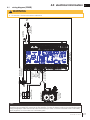
ELECTRODE
FLAME SENSOR
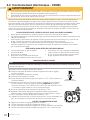
1.4 shut-off valve
CDI3E Illustrated
The shut-off valve is in the OFF position when the handle
is horizontal (see illustration).
The shut-off valve is in the ON position when the handle
is vertical.
A tool has been provided to shut off the gas.
note:

EN
W415-2801 / 01.21.20
9
general information
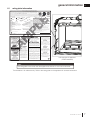
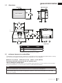
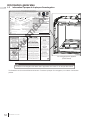
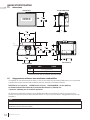
1.5 dimensions
This appliance must be recessed into a vented non-combustible wood-burning appliance (prefabricated or masonry)
only. The minimum appliance opening size in which the appliance is to be installed is:
HEIGHT 21 1/2" (54.6cm) WIDTH 29" (73.7cm) DEPTH * 14 3/8" (36.6cm)
The minimum allowable chimney fl ue size is 6" (152mm) round.
*Add 4" (102mm) for optional blower.
The minimum distance from the bottom of a combustible mantel projecting 3" (76mm) maximum from the wall to
the top of the appliance is 12" (30.4cm) (see "minimum mantel clearances" section).
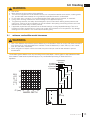
1.6 minimum clearance to combustibles
Ref. CDI3 CDI3E
A
13 7/16" [341mm]
B
7 1/2" [190mm]
* Dimension with optional blower kit installed.
A non-combustible hearth must protrude a minimum of 12" (30.5cm) from the appliance.
note:
A combustible hearth may be used if the appliance is raised 4" (102mm) above the hearth or if a Wolf Steel
raiser box is installed.
20
15
16
"
531mm
*
18
5
16
"
465mm
28
5
8
"
728mm
14
3
8
"
365mm
17
7
8
"
454mm
23
5
8
"
601mm
3"
2 PLS
A
B
15
3
16
"
386mm
4
3
16
"
106mm
SAFETY BARRIER
front view
right side view
top view
back view

W415-2801 / 01.21.20
EN
10
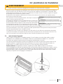
2.0 installation planning
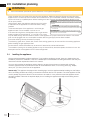
2.1 levelling the appliance
!
WARNING
• Risk of fi re! Maintain specifi ed air space clearances to vent pipe and appliance.
Clean out ashes from the inside of the wood-burning appliance. Make sure that the chimney and wood-burning
appliance are in a clean and sound condition and constructed of non-combustible materials. If necessary have any
repair work done by a qualifi ed person before installing the insert. Remove the existing appliance damper or lock
into an open position.
Using screws, attach the appliance warning tag to the inside
of the fi rebox of the appliance into which the insert is being
installed.
The sheet-metal parts of the appliance, in which the gas
appliance insert is to be installed, must not be cut.
If the wood-burning factory-built appliance has no gas access
hole(s) provided, an access hole of 1½ inch (38.1mm) or less
may be drilled through the lower sides or bottom of the appliance in a proper workman like manner. This access
hole must be plugged with non-combustible insulation after the gas supply line has been installed.
Ensure that existing chimney cleanouts fi t properly.
The refractory, glass doors, screen rails, screen mesh and log grates may be removed from the existing appliance
before installing the gas appliance insert.
Smoke shelves, shields and baffl es may be removed if attached by mechanical fasteners.
The ventilation openings in the existing appliance may be obstructed by the backer plates, aluminium trim etc. but
these parts are not to be applied so as to have an airtight seal.
W385-0199
Have an authorized dealer install the appliance. If you install the appliance yourself, have your dealer review your
installation plans and/or installation. Draw out a detailed plan of the installation including dimensions and verify the
dimensions with the requirements listed in this manual.
You may wish to adjust the appliance position slightly to ensure the vent does not intersect with a framing
member. Appliance must be positioned so that no combustibles are within, or can swing within (e.g. drapes,
doors), 48” (121.9cm) of the front of the appliance.
Inserts only: This appliance is equipped with 4 levelling legs. Level the appliance before installing into the fi nal po-
sition, as levelling will eliminate rocking or excessive noise when the fan is in operation. Once the appliance is level,
move it partially into place to allow for all connections to be made. It is not practical to level the appliance once it
has been installed. Determine the required depth prior to installing the appliance and adjust the levelling screws
accordingly.
W385-0199_B
WARNING: THIS FIREPLACE HAS BEEN CONVERTED FOR USE WITH A GAS FIREPLACE
INSERT ONLY AND CANNOT BE USED FOR BURNING WOOD OR SOLID FUELS UNLESS ALL ORIGINAL
PARTS HAVE BEEN REPLACED AND THE FIREPLACE IS RE-APPROVED BY THE AUTHORITY HAVING
JURISDICTION.
ATTENTION: CE FOYER A ETE CONVERTI AFIN D’ETRE UTILISE SEULEMENT
COMME FOYER ENCASTRE AU GAZ ET NE PEUT ETRE UTILSE POUR BRULER DU BOIS OU
TOUT AUTRE COMBUSTIBLE SOLIDE, SANS QUE TOUTES LES PIECES ORIGINALES AIENT
ETE REMPLACEES ET QUE LE FOYER SOIT APPROUVE DE NOUVEAU PAR LES AUTORITES
AYANT JURIDICTION.
ADVERTENCIA: ESTA CHIMENEA SE REMODELÓ PARA USARSE SOLO CON UNA
INSERCIÓN DE CHIMENEA A GAS Y NO PUEDE USARSE PARA QUEMAR MADERA NI COMBUSTIBLES
SÓLIDOS, A MENOS QUE SE HAYAN REEMPLAZADO TODAS LAS PIEZAS ORIGINALES, Y LA AUTORI-
DAD JURISDICCIONAL LA HAYA VUELTO A APROBAR.
CDI3E Illustrated

EN
W415-2801 / 01.21.20
11
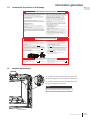
installation planning
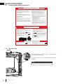
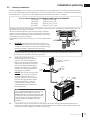
While the liners must be continuous from the appliance to the chimney cap, to achieve the needed length, they may
be coupled, using an approved coupler.
We recommend that exhaust vents that pass through unheated
spaces, such as tall exterior chimneys, be wrapped in a protective
sleeve to minimize condensation and reverse fl ow symptoms. See
"troubleshooting" section for details.
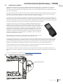
This appliance is approved for use with a 3" (76mm) exhaust and air
intake.
A. OUTSIDE: Slip the one end of a liner a minimum of 2"
(51mm) over the sleeve of the air terminal. Secure using
3 screws. Then seal the joint and screw heads with high
temperature sealant. Repeat with the other liner.
B. Gently stretch the liners to the
required lengths and insert into the
chimney. Trim and fi t the fl ashing
plate to suit the chimney termination.
Place the air terminal onto the top of
the chimney. Make weather tight by
sealing with caulking (not supplied).
Fasten to the chimney with screws
and plugs (not supplied).
C. INSIDE: Remove the securing screw
from the front of the vent mounting
assembly. Slide the vent mount
assembly from the track. Route the
fl ex liners through the slider. Attach
and secure the liners to the vent
mounting plate, ensuring that the
marked exhaust liner is attached to
the exhaust collar.
D. The appliance may now be pushed into the opening and the mounting plate assembly slid back into
the track, and the securing screw started. Once the appliance is in its fi nal position, tighten the securing
screw until the slider makes contact with the front stop.
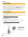
2.2 chimney connection
Chimney installation must conform to both national and local code requirements. The chimney must be lined with
one 3" (76mm) diameter liner for intake and one 3" (76mm) diameter liner for exhaust. The minimum and maximum
vent lengths are 10' (3m) and 45' (14m) respectively. Recommended kits come in 4 lengths:
2x 3" (51-76mm) DOUBLE PLY ALUMINUM LINER-INLET AND EXHAUST:
GDI-320KT VENT KIT 20FT (6M)
GDI-325KT VENT KIT 25 FT (7M)
GDI-335KT VENT KIT 35 FT (11M)
GDI-345KT VENT KIT 45 FT (14M)
MILL-PAC
2” (50.8MM)
OVERLAP
MOUNTING
PLATE
SLIDER
3” (76.2MM) LINERS
INTAKE
EXHAUST
VENT MOUNT
ASSEMBLY
SECURING
SCREW
SAFETY BARRIER
note:
We recommend that the other end of the exhaust liner be marked to eliminate the exhaust liner being
connected to the intake collar at the appliance.
CDI3E Illustrated
Flashing Plate
2” (51mm)
Overlap
Exhaust
Intake
note:
Prior to sliding the appliance into place, high
temperature-rated insulation should be
packed around the linear in the damper area
to prevent air fl ow from entering the chimney
from the home. Not doing so will have a
negative impact on the effi ciency of the
appliance.

W415-2801 / 01.21.20
EN
12
installation planning
2.3 gas installation
!
WARNING
• Risk of fi re, explosion, or asphyxiation. Ensure there are no ignition sources such as sparks or open fl ames.
• Support gas control when attaching gas supply pipe to prevent damaging gas line.
• Always light the pilot whether for the fi rst time or if the gas supply has run out with the glass door opened
or removed. Purging of the gas supply line should be performed by a qualifi ed service technician. Ensure
that a continuous gas fl ow is at the burner before closing the door. Ensure adequate ventilation. For gas and
electrical locations, see “dimensions” section.
• All gas connections must be contained within the appliance when complete (gas fi replaces only).
• High pressure will damage valve. Disconnect gas supply piping before testing gas line at test pressures above
1/2 PSIG.
• Valve settings have been factory set, do not change.
Installation and servicing to be done by a qualifi ed installer.
• Move the appliance into position and secure.
• If equipped with a fl ex connector, the appliance is designed to accept a 1/2” (13mm) gas supply. Without the
connector, it is designed to accept a 3/8” (9.5mm) gas supply. The appliance is equipped with a manual shut
off valve to turn off the gas supply to the appliance.
• Connect the gas supply in accordance to local codes. In the absence of local codes, install to the current
CAN/CSA-B149.1 Installation Code in Canada or to the current National Fuel Gas Code, ANSI Z223.1 / NFPA
54 in the United States.
• When fl exing any gas line, support the gas valve so that the lines are not bent or kinked.
• The gas line fl ex-connector should be installed to provide suffi cient movement for shifting the burner assembly
on its side to aid with servicing components.
• Check for gas leaks by brushing on a soap and water solution. Do not use open fl ame.
• This appliance is designed to accept a 1/2" (13mm) gas supply. The appliance is also equipped with a manual
shut-off valve to turn off the gas supply to the appliance.
Turn brass elbow until it
lines up with the hole in
the back. Use a backup
wrench on the ball valve
fi tting.
Alternate gas knockout for
rear gas installation.
We recommend the following method of sealing off the damper area around the liner:
Measure the throat of the appliance and mark this shape on a piece of 24 gauge sheet metal (fl ue cover). Cut a 6
3/4" (171mm) hole to lie directly below the appliance fl ue opening. Allow 2" of material for a fl ange on all sides and
cut to these measurements. Bend down the fl anges. If you have never done this before, it might be a good idea to
make a cardboard pattern and test it fi rst. Fasten this fl ue cover in position as high as possible with two masonry
screws per side through the fl anges into the appliance.

EN
W415-2801 / 01.21.20
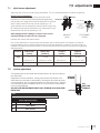
13
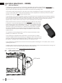
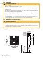
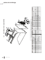
3.0 fi nishing
Combustible mantel clearance can vary according to the mantel depth. Use the graph to help evaluate the clear-
ance needed. These same requirements apply to any combustibles protruding on either side of the
appliance.
3”
12”
5”
4”
MANTEL DEPTH
0” (mm)
+
(
,
*
+
7
0
$
1
7
(
/
6”
15”
16”
17”
3.1 minimum combustible mantel clearances
12”
(30.5cm)
17”
(43.2cm)
16”
(40.6cm)
15”
(38.1cm)
6”(152.4mm)
MANTEL
5”(127mm)
3” (76.2mm)
4”(101.6mm)
20
15/16
”
(53.1cm)
6”(152mm)
!
WARNING
• Risk of fi re!
• Never obstruct the front opening of the appliance.
• The front of the appliance must be fi nished with any non-combustible materials such as brick, marble, granite,
etc., provided that these materials do not go below the specifi ed dimension, as illustrated.
• Do not strike, slam, or scratch. Do not operate appliance with glass removed, cracked, or scratched.
• Facing and/or fi nishing material must never overhang into the appliance opening.
• The glass door assembly is a safety device designed to pivot forward when relieving excess pressure that
might occur. Finishing or other materials must not be located in the opening surrounding the door as this will
interfere with the doors ability to relieve pressure.
• If applicable, drywall dust will penetrate into the blower bearings, causing irreparable damage. Care must
be taken to prevent drywall dust from coming into contact with the blower or its compartment. Any damage
resulting from this condition is not covered by the warranty policy.
!
WARNING
• Risk of fi re. Maintain all specifi ed air space clearances to combustibles. Failure to comply with these instructions
may cause a fi re or cause the appliance to overheat. Ensure all clearances (i.e. back, side, top, vent, mantel,
front, etc.) are clearly maintained.
• When using paint or lacquer to fi nish the mantel, the paint or lacquer must be heat resistant to prevent
discolouration.

W415-2801 / 01.21.20
EN
14
fi nishing
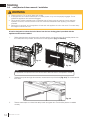
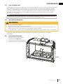
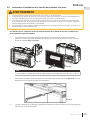
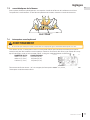
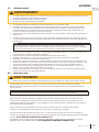
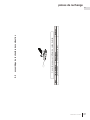
3.2 safety barrier & door removal / installation
A barrier designed to reduce the risk of burns from the hot viewing glass is provided with the
appliance and must be installed.
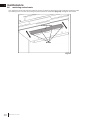
1. Before the glass door can be removed, the safety barrier must be removed. Lift the safety barrier from
the 4 tabs, tilt the top forward, and remove from the appliance (Fig. 3-1 and 3-2).
2. Release the top left and right door latches, located at the top of the door (Fig. 3-3). Tilt forward and lift
from slots.
3. Reverse these steps to re-install the safety barrier and glass door. Ensure safety barrier is installed
correctly.
!
WARNING
• Glass may be hot. Do not touch glass until cooled.
• If equipped with door latches that are part of a safety system, they must be properly engaged. Do not
operate the appliance with latches disengaged.
• Facing and/or fi nishing materials must not interfere with air fl ow through air openings, louvre openings,
operation of louvres, or doors/access for service. Observe all clearances when applying combustible
materials.
• Before door is removed, turn the appliance off and wait until appliance is cool to the touch. Doors are heavy
and fragile so handle with care.
Fig. 3-2
note:
If applicable, the optional front must be removed to allow the door to be opened or closed.
Fig. 3-3
CDI3E Illustrated
CDI3E Illustrated
SAFETY BARRIER
Fig. 3-1
SAFETY BARRIER

EN
W415-2801 / 01.21.20
15
fi nishing
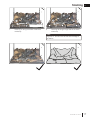
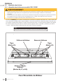
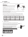
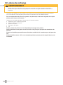
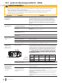
3.3 log placement
3.3.1 log placement for CDI3 / CDI3E
!
WARNING
• Failure to position the logs in accordance with these diagrams or failure to use only logs specifi cally approved
with this appliance may result in property damage or personal injury.
• Logs must be placed in their exact location in the appliance. Do not modify the proper log positions, since
appliance may not function properly and delayed ignition may occur.
• The logs are fragile and should be handled with care.
If applicable, insert the following statement:
“PHAZER™ logs [and glowing embers], exclusive to Napoleon/Continental, provide a unique and realistic
glowing effect that is different in every installation. Take the time to carefully position the glowing embers for a
maximum glowing effect. Log colours may vary. During the initial use of the appliance, the colours will become
more uniform as colour pigments burn in during the heat-activated curing process.”
note:
Log numbers are located on the bottom or back of the logs.
IF APPLICABLE, INSERT DRAWING OF BURNER/SUPPORT WITH APPROPRIATE LA-
BELS (I.E. STUDS, PILOT SHIELD, BURNER PORTS, ETC.).
IF NOT APPLICABLE, HIDE THIS SECTION AND USE BOXES BELOW.
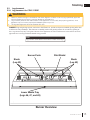
Burner Overview
Insert only if
applicable ---->
PHAZER™ log and glowing embers, exclusive to Wolf Steel Ltd., provide a unique and realistic glowing effect that
is different in every installation. Take the time to carefully position the glowing embers for a maximum glowing ef-
fect. Log colours may vary. During the initial use of the appliance, the colours will become more uniform as colour
pigments burn in during the heat-activated curing process.
Pilot ShieldBurner Ports
Studs
(Log #2)
Studs
(Log #3)
Lower Media Tray
(Logs #6, #7, and #8)
A1
A2 B2B1
note:
Log numbers are located on the bottom or back of the logs.

W415-2801 / 01.21.20
EN
16
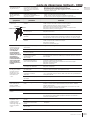
fi nishing
PLACE TEXT BOX HERE.
NOTE: ENSURE NOMENCLATURE IS
CONSISTENT THROUGHOUT.
PLACE TEXT BOX HERE.
NOTE: ENSURE NOMENCLATURE IS
CONSISTENT THROUGHOUT.
PLACE TEXT BOX HERE.
NOTE: ENSURE NOMENCLATURE IS
CONSISTENT THROUGHOUT.
PLACE TEXT BOX HERE.
NOTE: ENSURE NOMENCLATURE IS
CONSISTENT THROUGHOUT.
PLACE TEXT BOX HERE.
NOTE: ENSURE NOMENCLATURE IS
CONSISTENT THROUGHOUT.
PLACE TEXT BOX HERE.
NOTE: ENSURE NOMENCLATURE IS
CONSISTENT THROUGHOUT.
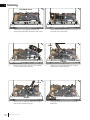
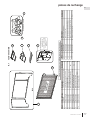
1
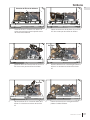
Pilot Shield Notch
1
A1
A2
3
1
B1
B2
2
3
1
3
2
Notches
4
Notch
1
2
1
4
Notches
5
Notch
1
2
4
5
6
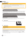
1. Place log #1 snug against the back wall,
ensuring the notch fi ts around the pilot shield.
2. Place the two holes in log #3 on A1 and A2. Do
not cover any burner ports.
3. Place the two holes in log #2 on B1 and B2.
Do not cover any burner ports.
4. Place log #4 on the left-side notch of log #1
and the two notches of log #3.
5. Place log #5 on the right-side notch of log #1
and the two notches of log #2.
6. Place log #6 along the left side of the lower
media tray.

EN
W415-2801 / 01.21.20
17
fi nishing
PLACE TEXT BOX HERE.
NOTE: ENSURE NOMENCLATURE IS
CONSISTENT THROUGHOUT.
PLACE TEXT BOX HERE.
NOTE: ENSURE NOMENCLATURE IS
CONSISTENT THROUGHOUT.
IF SPACE IS LEFT OVER, USE THIS BOX TO
SHOW CORRECT FINAL LOG
PLACEMENT WITH PHOTOS.
IF SPACE IS LEFT OVER, USE THIS BOX TO
SHOW CORRECT FINAL LOG PLACEMENT
WITH LINE DRAWINGS.
IF NOT, USE BOXES AS ABOVE.
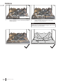
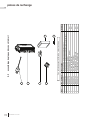
1
2
4
5
6
7
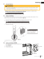
8. Place log #8 along the right side of the lower
media tray.
7. Place log #7 along the centre of the lower
media tray.
1
3
2
3
4
5
6
7
8
note:
Logs #6, #7, and #8 must be fl ush with the edge of
the fi rebox.

W415-2801 / 01.21.20
EN
18
fi nishing
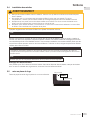
3.4 media installation
3.5 logo placement
!
WARNING
• Clean the glass media prior to installation. Before applying the cleaned glass, ensure that it is dry.
• Do not change or substitute the glass media material provided with this appliance. If replacing, use only the
replacement glass media available from your local authorized dealer / distributor.
• Glass media over the burner must not be more than one layer high. More than one layer over the burner will
cause fl ame lifting and sooting problems.
• Do not place any media (glass or vermiculite) in or around the pilot opening. This will interfere with the pilot
operation.
Remove the backing of the logo supplied and place, as illustrated.
1/2"(12.7mm)
LOGO
1/2"(12.7mm)
note:
There must only be a single layer of glass media over the burner tube.
Evenly spread the glass media onto the media tray, covering the burner tube and tray.
Ensure no glass media falls into the pilot opening. If this happens, insert a clean bag into your vacuum cleaner and
vacuum out the glass media. Replacement glass can be purchases from your local authorized dealer / distributor.
Glass media over the burner ports may cause a "puffi ng" sound. To eliminate this sound, simply push the media
away from the burner ports.
note:
The distribution of glass media over the burner ports will infl uence the fl ame height. When the fl ames impinge on
the glass, the glass may discolour slightly and the edges may soften.
note:
Do not use more media than what was supplied with the appliance.
Cleaning Glass Media
Glass media may have a fi ne oil residue that needs to be cleaned prior to installation. Clean the glass with mild
dish soap, drain, rinse thoroughly, and dry before placing over the burner.
3.6 glowing embers
T
ear the embers into pieces and loosely layer above the burner ports covering the burner area. Care should be
taken to shred the embers into thin, small irregular pieces as only the exposed edges of the fi bre hairs will glow.
The ember material will only glow when exposed to direct fl ame; however, care should be taken to not
b
lock off the burner ports.
Blocked burner ports can cause an incorrect fl ame pattern, carbon deposits and delayed ignition. PHAZER™
logs glow when exposed to direct fl ame. Use only certifi ed “glowing embers” and PHAZER™ logs available from
your local authorized dealer / distributor.
!
WARNING
• Completely blocking the burner ports can cause an incorrect fl ame pattern, carbon deposits and delayed
ignition.

EN
W415-2801 / 01.21.20
19
fi nishing
Randomly place the charcoal embers along the front and sides of the log support in a realistic manner.
Fine dust found in the bottom of the bag should not be used.
!
WARNING
• Do not block or close off the burner ports. Blocked ports can cause an incorrect fl ame pattern, carbon
deposits and delayed ignition.
• When supplied, charcoal embers, charcoal lumps and vermiculite are not to be placed on the burner.
note:
Charcoal embers are not to be placed on the burner.
3.7 charcoal embers
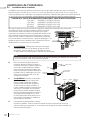
4 AA batteries must be installed into the receiver before the appliance can operate by battery backup. The re-
ceiver is located in the bottom right corner of the appliance (Fig. 3-4).
1. Remove the battery cover plate by pushing the two tabs that hold the cover in place.
2. Remove the 4 AA batteries in the battery holder and replace with new ones.
3. Reinstall the cover plate.
note:
Ensure the 3 position slider
switch is in the "REMOTE"
position (middle position).
Fig. 3-4
CDI3E Illustrated
3.8 battery installation
note:
Note the polarity of the batteries and insert as indicated on the cover (+/-).
3.9 battery installation (CDI3E)
1. Remove battery holder by sliding it forward from the
bracket (Fig. 3-5).
2. Install 4 batteries.
3. Reinstall battery holder.
Fig. 3-5
Battery Holder
Bracket
Fig
. 3-4
C

W415-2801 / 01.21.20
EN
20
fi nishing
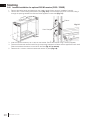
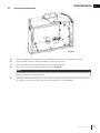
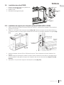
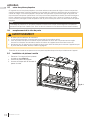
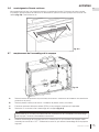
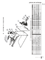
3.10 bracket installation for optional F45/60 receiver (CDI3 / CDI3E)
1. Remove the safety barrier and glass door (see "safety barrier & door removal / installation" section).
2. Remove the 1 screw holding the bracket in place (Fig. 3-6). Lift the bracket up and out of the slots, lifting it
through the opening between the fi rebox and the appliance's outer shell (Fig. 3-7).
3. Insert the optional receiver (F45 or F60) into the bracket. Secure the receiver using 2 screws (supplied).
4. Place the bracket and receiver back through the opening between the fi rebox and the appliance's outer shell.
Slide the bracket and receiver into and down the slots (Fig. 3-7 in reverse).
5. Resecure the 1 screw to hold the bracket and receiver in place (Fig. 3-6).
Fig. 3-6
Fig. 3-7
Firebox
Outer Shell
La page est en cours de chargement...
La page est en cours de chargement...
La page est en cours de chargement...
La page est en cours de chargement...
La page est en cours de chargement...
La page est en cours de chargement...
La page est en cours de chargement...
La page est en cours de chargement...
La page est en cours de chargement...
La page est en cours de chargement...
La page est en cours de chargement...
La page est en cours de chargement...
La page est en cours de chargement...
La page est en cours de chargement...
La page est en cours de chargement...
La page est en cours de chargement...
La page est en cours de chargement...
La page est en cours de chargement...
La page est en cours de chargement...
La page est en cours de chargement...
La page est en cours de chargement...
La page est en cours de chargement...
La page est en cours de chargement...
La page est en cours de chargement...
La page est en cours de chargement...
La page est en cours de chargement...
La page est en cours de chargement...
La page est en cours de chargement...
La page est en cours de chargement...
La page est en cours de chargement...
La page est en cours de chargement...
La page est en cours de chargement...
La page est en cours de chargement...
La page est en cours de chargement...
La page est en cours de chargement...
La page est en cours de chargement...
La page est en cours de chargement...
La page est en cours de chargement...
La page est en cours de chargement...
La page est en cours de chargement...
La page est en cours de chargement...
La page est en cours de chargement...
La page est en cours de chargement...
La page est en cours de chargement...
La page est en cours de chargement...
La page est en cours de chargement...
La page est en cours de chargement...
La page est en cours de chargement...
La page est en cours de chargement...
La page est en cours de chargement...
La page est en cours de chargement...
La page est en cours de chargement...
La page est en cours de chargement...
La page est en cours de chargement...
La page est en cours de chargement...
La page est en cours de chargement...
La page est en cours de chargement...
La page est en cours de chargement...
La page est en cours de chargement...
La page est en cours de chargement...
La page est en cours de chargement...
La page est en cours de chargement...
La page est en cours de chargement...
La page est en cours de chargement...
La page est en cours de chargement...
La page est en cours de chargement...
La page est en cours de chargement...
La page est en cours de chargement...
-
 1
1
-
 2
2
-
 3
3
-
 4
4
-
 5
5
-
 6
6
-
 7
7
-
 8
8
-
 9
9
-
 10
10
-
 11
11
-
 12
12
-
 13
13
-
 14
14
-
 15
15
-
 16
16
-
 17
17
-
 18
18
-
 19
19
-
 20
20
-
 21
21
-
 22
22
-
 23
23
-
 24
24
-
 25
25
-
 26
26
-
 27
27
-
 28
28
-
 29
29
-
 30
30
-
 31
31
-
 32
32
-
 33
33
-
 34
34
-
 35
35
-
 36
36
-
 37
37
-
 38
38
-
 39
39
-
 40
40
-
 41
41
-
 42
42
-
 43
43
-
 44
44
-
 45
45
-
 46
46
-
 47
47
-
 48
48
-
 49
49
-
 50
50
-
 51
51
-
 52
52
-
 53
53
-
 54
54
-
 55
55
-
 56
56
-
 57
57
-
 58
58
-
 59
59
-
 60
60
-
 61
61
-
 62
62
-
 63
63
-
 64
64
-
 65
65
-
 66
66
-
 67
67
-
 68
68
-
 69
69
-
 70
70
-
 71
71
-
 72
72
-
 73
73
-
 74
74
-
 75
75
-
 76
76
-
 77
77
-
 78
78
-
 79
79
-
 80
80
-
 81
81
-
 82
82
-
 83
83
-
 84
84
-
 85
85
-
 86
86
-
 87
87
-
 88
88


Continental Fireplaces CDI3NE Le manuel du propriétaire
- Catégorie
- Cheminées
- Taper
- Le manuel du propriétaire
dans d''autres langues
Documents connexes
Autres documents
-
NAPOLEON Bayfield GDS25N-1 Le manuel du propriétaire
-
NAPOLEON GDI-30NSB Manuel utilisateur
-
-
-
-
-
-
-
-