
AT-7000
Advanced Wire Tracers
AT-7020
AT-7030
User Manual
Manuel de l’utilisateur
Manual de usuario


AT-7000
Advanced Wire Tracer
AT-7020
AT-7030
User Manual
10/2017, 4394127 Rev B
©2017 Amprobe Test Tools.
All rights reserved.
English

Limited Warranty and Limitation of Liability
Your Amprobe product will be free from defects in material and workmanship for 1 year from
the date of purchase. This warranty does not cover fuses, disposable batteries or damage from
accident, neglect, misuse, alteration, contamination, or abnormal conditions of operation or
handling. Resellers are not authorized to extend any other warranty on Amprobe’s behalf.
To obtain service during the warranty period, return the product with proof of purchase to
an authorized Amprobe Test Tools Service Center or to an Amprobe dealer or distributor. See
Repair Section for details. THIS WARRANTY IS YOUR ONLY REMEDY. ALL OTHER WARRANTIES
- WHETHER EXPRESS, IMPLIED OR STAUTORY - INCLUDING IMPLIED WARRANTIES OF
FITNESS FOR A PARTICULAR PURPOSE OR MERCHANTABILITY, ARE HEREBY DISCLAIMED.
MANUFACTURER SHALL NOT BE LIABLE FOR ANY SPECIAL, INDIRECT, INCIDENTAL OR
CONSEQUENTIAL DAMAGES OR LOSSES, ARISING FROM ANY CAUSE OR THEORY. Since some
states or countries do not allow the exclusion or limitation of an implied warranty or of
incidental or consequential damages, this limitation of liability may not apply to you.
Repair
All Amprobe tools returned for warranty or non-warranty repair or for calibration should
be accompanied by the following: your name, company’s name, address, telephone number,
and proof of purchase. Additionally, please include a brief description of the problem or
the service requested and include the test leads with the meter. Non-warranty repair or
replacement charges should be remitted in the form of a check, a money order, credit card
with expiration date, or a purchase order made payable to Amprobe.
In-warranty Repairs and Replacement – All Countries
Please read the warranty statement and check your battery before requesting repair. During
the warranty period, any defective test tool can be returned to your Amprobe distributor for
an exchange for the same or like product. Please check the “Where to Buy” section on
www.Amprobe.com for a list of distributors near you. Additionally, in the United States and
Canada, in-warranty repair and replacement units can also be sent to an Amprobe Service
Center (see address below).
Non-warranty Repairs and Replacement – United States and Canada
Non-warranty repairs in the United States and Canada should be sent to an Amprobe Service
Center. Call Amprobe or inquire at your point of purchase for current repair and replacement
rates.
USA: Canada:
Amprobe Amprobe
Everett, WA 98203 Mississauga, ON L4Z 1X9
Tel: 888-993-5853 Tel: 905-890-7600
Fax: 425-446-6390 Fax: 905-890-6866
Non-warranty Repairs and Replacement – Europe
European non-warranty units can be replaced by your Amprobe distributor for a nominal
charge. Please check the “Where to Buy” section on www.Amprobe.eu for a list of
distributors near you.
Amprobe Europe*
Beha-Amprobe
In den Engematten 14
79286 Glottertal, Germany
Tel.: +49 (0) 7684 8009 - 0
www.Amprobe.eu
*(Correspondence only – no repair or replacement available from this address. European
customers please contact your distributor.)

1
AT-7000 Series
CONTENTS
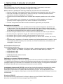
1. PRECAUTIONS AND SAFETY MEASURES ............................................................. 2
2. KIT COMPONENTS ................................................................................................. 5
2.1 AT-7000-R Receiver ........................................................................................................6
2.2 AT-7000-T Transmitter ...................................................................................................8
2.3 TL-7000 Test Lead & Accessory Kit ................................................................................9
2.4 SC-7000 Signal Clamp (AT-7030 Kit) ............................................................................10
3. MAIN APPLICATIONS ............................................................................................ 11
3.1 Tracing Energized Wires
• SMART SENSOR .......................................................................................................... 12
• TIP SENSOR Energized ................................................................................................ 14
3.2 Tracing De-Energized Wires
• TIP SENSOR De-Energized ..........................................................................................16
3.3 Identifying Breakers and Fuses
• BREAKER Energized (Energized Circuits) ..................................................................18
• BREAKER De-Energized (De-Energized Circuits) ......................................................20
3.4 Non-Contact Voltage Mode (NCV) ...............................................................................21
4. SPECIAL APPLICATIONS ........................................................................................ 22
4.1 GFCI-Protected Circuit Wire Tracing .............................................................................22
4.2 Finding Breaks/Opens ................................................................................................... 22
4.3 Finding Shorts ...............................................................................................................23
4.4 Tracing Wires in Metal Conduit ...................................................................................24
4.5 Tracing Non-Metallic Pipes and Conduits ....................................................................24
4.6 Tracing Shielded Wires ..................................................................................................24
4.7 Tracing Underground Wires ..........................................................................................25
4.8 Tracing Low Voltage Wires and Data Cables ...............................................................25
4.9 Sorting Bundled Wires ..................................................................................................25
4.10 No Access to Bare Conductors (Signal Clamp) ...........................................................26
4.11 Locating Loads (Signal Clamp) .................................................................................... 27
5. MAINTENANCE - BATTERY AND FUSE REPLACEMENT ........................................ 28
6. SPECIFICATIONS ..................................................................................................... 31

2
1. PRECAUTIONS AND SAFETY MEASURES
General
For your own safety and to avoid damage to the instrument we suggest you to follow the
procedures listed below:
NOTE: Before and during measurements be diligent to follow the instructions.
• Make sure that the electrical instrument is operating properly before use.
• Before attaching any of the conductors, make sure that the voltage present in the
conductor is in the range of the instrument.
• Keep the instruments in their carrying case when not in use.
• If the transmitter or receiver will not be used for a long time, remove the batteries to
prevent leakage in the instruments.
• Use Amprobe approved cables and accessories only.
Safety precautions
• In many instances, you will be working with dangerous level of voltage and/or current,
therefore, it is important that you avoid direct contact with any uninsulated, current
carrying surfaces. Wear appropriate insulated gloves and protective clothing in
hazardous voltage areas
• Do not measure voltage or current in wet or damp or dusty places
• Do not measure in presence of gas, explosive materials or combustibles
• Do not touch the circuit under test if no measurement is being taken
• Do not touch exposed metal parts, unused terminals, circuits and so on
• Do not use the instrument if it seems to be malfunctioning (i.e. if you notice
deformations, breaks, leakage of substances, and absence of messages on the display
and so on.)
Safety information
The product complies with:
• UL/IEC/EN 61010-1, CAN/CSA C22.2 No. 61010-1, Pollution Degree 2, Measurement
category IV 600 V (AT-7000-R); Category IV 300V MAX (AT-7000-T)
• IEC/EN 61010-2-033
• IEC/EN 61010-2-032
• IEC/EN 61010-031 (test leads)
• EMC IEC/EN 61326-1
Conforms to relevant South Korean EMC standards.
Korea (KCC): Class A Equipment (Industrial Broadcasting & Communication Equipment)
[1]
[1]
This product meets requirements for industrial (Class A) electromagnetic wave equipment
and the seller or user should take notice of it. This equipment is intended for use in business
environments and is not to be used in homes.
Measurement Category III (CAT III) is applicable to test and measuring circuits connected
to the distribution part of the building’s low-voltage MAINS installation. This part of the
installation is expected to have a minimum of two levels of over-current protective devices
between the transformer and possible connecting points
Measurement Category IV (CAT IV) is for circuits that are directly connected to the primary
utility power source for a given building or between the building power supply and the
main distribution board. Such equipment may include electricity tariff meters and primary
over current protection devices.
CENELEC Directives
The instruments conform to CENELEC Low-voltage directive 2014/35/EU and Electromagnetic
compatibility directive 2014/35/EU.

3
�Warnings: Read Before Using
To avoid possible electric shock or personal injury:
• Use the Meter only as specified in this manual or the protection provided by the
instrument might be impaired.
• Avoid working alone so assistance can be rendered.
• Never measure ac current while the test leads are inserted into the input jacks.
• Do not use the Meter in wet or damp environments.
• Do not use the Meter if it appears damaged. Inspect the Meter before use. Look
for cracks or missing plastic. Pay particular attention to the insulation around the
connectors.
• Inspect the test leads before use. Do not use them if insulation is damaged or metal is
exposed.
• Check the test leads for continuity. Replace damaged test leads before using the Meter.
• Have the Meter serviced only by qualified service personnel.
• Use extreme caution when working around bare conductors or bus bars. Contact with
the conductor could result in electric shock.
• Do not hold the Meter anywhere beyond the tactile barrier.
• Do not apply more than the rated voltage, as marked on the Meter, between the
terminals or between any terminal and earth ground.
• Remove test leads from the Meter before opening the Meter case or battery cover.
• Never operate the Meter with the battery cover removed or the case open.
• Never remove the battery cover or open the case of the Meter without first removing
the test leads from a live conductor.
• Use caution when working with voltages above 30 V ac rms, 42 V ac peak, or 60 V dc.
These voltages pose a shock hazard.
• Do not attempt to measure any voltage that might exceed the maximum range of the
Meter.
• Use the proper terminals, function, and range for your measurements.
• Do not operate the Meter around explosive gas, vapor, or dust.
• When using probes, keep fingers behind the finger guards.
• When making electrical connections, connect the common test lead before
connecting the live test lead; when disconnecting, disconnect the live test lead before
disconnecting the common test lead.
• To avoid false readings that can lead to electrical shock and injury, replace the battery
as soon as the low battery indicator appears. Check Meter operation on a known
source before and after use.
• When servicing, use only specified user serviceable replacement parts.
• Adhere to local and national safety codes. Individual protective equipment must
be used to prevent shock and arc blast injury where hazardous live conductors are
exposed.
• Only use the test lead provided with the Meter or UL Listed Probe Assembly rated CAT
IV 600V or better.
• Do not use HOT STICK to operate the AT-7000-R Receiver around voltage more than 600V
1. PRECAUTIONS AND SAFETY MEASURES

4
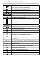
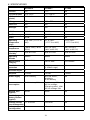
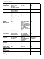
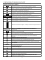
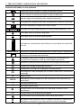
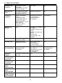
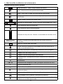
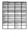
Symbols used in this product
Battery status – Displays the remaining battery charge
Home – Return to home screen when selected
Help – Enters to the help mode when selected
Settings – Enters to the settings menu when selected
Volume– Displays the volume in four levels
Sensitivity indicator – Displays the sensitivity level from 1 to 10.
Icon indicating energized system
Icon indicating de-energized system
99
SIGNAL
Signal strength indicator – Shows the strength of the signal
from 0 to 99
MAN/AUTO
Shows whether the sensitivity adjustment is in Manual or
Automatic mode
Indicates the volume is muted.
Lock indicates if the Auto sensitivity lock is active
(Only in Auto sensitivity mode)
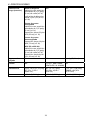
Application and removal from hazardous live conductors permitted
Caution! Risk of electric shock.
�
Caution! Refer to the explanation in this Manual.
T
The equipment is protected by double insulation or
reinforced insulation.
J
Earth (Ground).
CAT IV
Overvoltage up to Category IV 300V (transient protection up to 6kV)
B
Alternating Current (AC).
F
Direct Current (DC).
)
Conforms to relevant North American Safety Standards.
P
Complies with European Directives.
Conforms to relevant Australian standards.
Conforms to relevant South Korean EMC standards.
=
Do not dispose of this product as unsorted municipal waste. Contact
a qualified recycler.
1. PRECAUTIONS AND SAFETY MEASURES

5
This manual contains information and warnings that must be followed for operating the
tester safely and maintaining the tester in a safe operating condition. If the tester is used in
a manner not specified by the manufacturer, the protection provided by the tester may be
impaired. This tester meets water and dust protection IP40 per IEC60529 Ed 2.1 (2001). Do
not use in rainfall! The tester is double insulated for protection per EN61010-1:2010 3rd Ed
to CAT IV 600V. (AT-7000-R) and CAT IV 300V MAX (AT-7000-T)
CAUTION: Do not connect the Transmitter to a separate ground in Electrically Susceptible
Patient areas of a health care facility. Make the ground connection first and disconnect it
last.
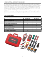
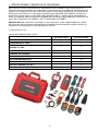
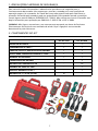
2. KIT COMPONENTS
Your shipping box should include:
AT-7020 KIT AT-7030 KIT
AT-7000-R RECEIVER 1 1
AT-7000-T TRANSMITTER 1 1
TL-7000 TEST LEAD AND ACCESSORY KIT 1 1
CC-7000 HARD CARRYING CASE 1 1
USER MANUAL 1 1
BATTERY CHARGERS - 3
RECHARGEABLE BATTERIES - 10
SC-7000 SIGNAL CLAMP - 1
HS-1 MAGNETIC HANGER - 1
1.5 V AA (IEC R6) BATTERIES 10 -
1. PRECAUTIONS AND SAFETY MEASURES

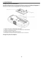
6
2. KIT COMPONENTS
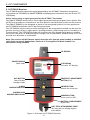
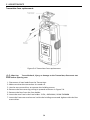
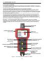
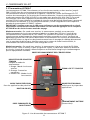
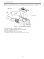
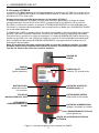
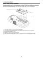
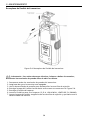
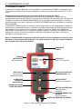
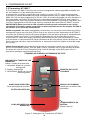
2.1 AT-7000-R Receiver
The AT-7000-R Receiver detects the signal generated by the AT-7000-T transmitter along wires
using either the TIP SENSOR or SMART SENSOR and displays this information on the full color TFT
LCD display.
Active tracing using a signal generated by the AT-7000-T Transmitter
The SMART SENSOR works with a 6 kHz signal generated along energized wires (above 30V
AC/DC) and provides an indication of the wire position and direction relative to the receiver.
The SMART SENSOR is not designed to work on de-energized systems; for that application
the TIP SENSOR should be used in de-energized mode.
The TIP SENSOR may be used on either energized or de-energized wires and can be used for
general tracing, tracing in tight spaces, locating breakers, pinpointing wires in bundles or in
junction boxes. The TIP SENSOR mode will pinpoint the wire location with both an audible
and visual indication of detected signal strength, but unlike SMART SENSOR mode it will not
provide wire direction or orientation.
Note: The receiver will NOT detect signals from the wire through metal conduit or shielded
cable. Refer to Special Applications, section 4.4 “Tracing Wires In Metal Conduit” for
alternative tracing methods.
TIP SENSOR
LCD DISPLAY
Full color TFT display
SENSITIVITY ADJUSTMENT
BUTTON (-/+)
SMART SENSOR
(Back side)
NCV BUTTON
Non-Contact
Voltage mode
4-WAY
NAVIGATION KEYS
RUBBER OVER
MOLDED ENCLOSURE
ENTER BUTTON
Selects the functions
POWER BUTTON
Turns unit On / Off
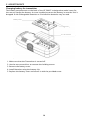
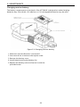
BATTERY COMPARTMENT
(Back side)
HOT STICK ATTACHMENT POINT
(Do not use for voltage higher
than 600V)
Figure 1: Overview of AT-7000-R Receiver

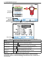
7
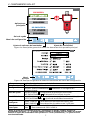
ENERGIZED:
DE-ENERGIZED:
--
Main applications
Setting menu
Help guide
Buzzer volume adjustment
Sensitivity adjustment
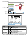
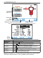
Figure 1a: Overview of all elements on home screen
Home menu
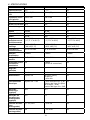
Figure 1b: Overview of all elements on the setting menu
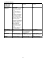
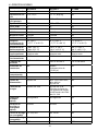
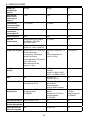
Language English, French, German, Spanish, Italian
Backlight 25%, 50%, 75%, 100%
Setting
DEFAULT
: Restore default settings
Help Guidance
ON
: Device will guide you through each mode
OFF : Device will start without guidance
Sensitivity*
MAN
: Manual sensitivity adjustment (+) and (-) keys
AUTO : Auto sensitivity adjustment
Smart Sensor Range
SHORT
: For wire detection up to 3 feet
LONG : For wire detection between 3 and 20 feet
Breaker Voltage
110V
: For 110V to 120V systems
220V
: For 220V to 240V systems
*Note: The Auto and Manual sensitivity mode can be easily changed by pressing the + and
– key at the same time when the receiver is in a tracing mode. When sensitivity mode is set
to “Auto” manual adjustment is disabled.
2. KIT COMPONENTS

8
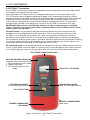
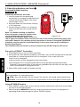
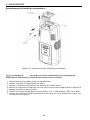
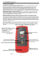
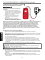
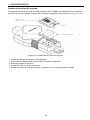
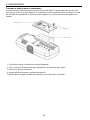
2.2 AT-7000-T Transmitter
The AT-7000-T Transmitter works on energized and de-energized circuits up to 300V AC/DC
in Category I-IV electrical environments.
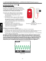
The transmitter will measure the line voltage and display it on the transmitter’s color
TFT LCD display screen. Based on detected voltage it will automatically switch to either
energized mode (30 to 300V AC/DC) or de-energized mode (0 to 30V AC/DC). The energized
mode uses a lower transmission frequency (6kHz) than de-energized mode (33 kHz) to
reduce signal coupling with nearby metallic objects and improve results. If the circuit is
energized the red LED in the upper left corner of the AT-7000-T transmitter will light.
IMPORTANT! Note that the red LED light will turn on when connected to an energized
circuit. Select the correct energized or de-energized mode on the AT-7000-R receiver when
choosing your tracing mode.
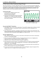
Energized mode: In energized mode the transmitter draws very low current from the
energized circuit and generates a 6.25 kHz signal. This is very important feature of the
AT-7000-T, since drawing current does not inject any signal that would harm sensitive
equipment connected to the circuit. The signal is also generated in a direct path between
the transmitter and the power source, thus NOT placing a signal onto any branches enabling
wiring tracing directly back to the breaker panel. Please note that due to this feature, the
transmitter has to be connected on the load side of the circuit.
De-energized mode: In de-energized mode the transmitter injects a 32.8 kHz signal onto the
circuit. In this mode, since the signal is injected, it will travel through all the circuit branches.
It is a high frequency, very low energy signal that will not harm any sensitive equipment
RED LED VOLTAGE INDICATOR
Indicates the transmitter mode
1. Red: Energized circuit mode
2. Amber: Overload
3. OFF: De-energized circuit
mode
LOW/PRECISION MODE
For precision applications
ON / OFF BUTTON
COLOR TFT LCD DISPLAY
TEST LEADS CONNECTION JACKS
HIGH/NORMAL MODE
Used for most applications
BATTERY COMPARTMENT
(Back side)
RUBBER OVERMOLDED
ENCLOSURE
Figure 2: Overview of AT-7000-T Transmitter
2. KIT COMPONENTS

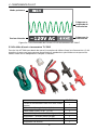
9
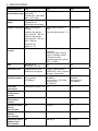
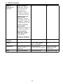
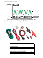
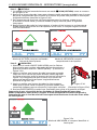
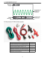
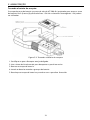
Power Mode
Detected Voltage
Transmission
Frequency &
Amplitude
Transmission
Frequency
Figure 2a: Overview of AT-7000-T Transmitter LCD Screen
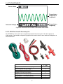
2.3 TL-7000 Test Lead & Accessory Kit
All AT-7000 kits come with our complete test leads & accessory kit. The kit supports a
wide range of standard and specialty applications and contains test leads and adaptors as
outlined below:
TL-7000
US power cord with banana plugs 1
Test lead (red). 6.4 ft. (1.9m) 1
Test lead (green), 25 ft. (7.7 m) 1
Alligator clip set (red, black) 1
Plug adaptor – flat pin (red) 1
Plug adaptor – round pin (black) 1
Light socket adaptor 1
2. KIT COMPONENTS

10
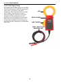
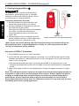
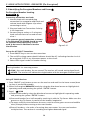
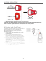
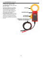
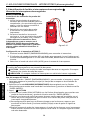
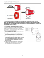
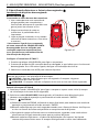
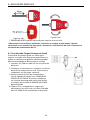
2.4 SC-7000 Signal Clamp
(included with AT-7030, option for AT-7020)
The clamp accessory is used for applications
when there is no access to the bare
conductors. The clamp attachment enables
the AT-7000-T Transmitter to induce a
signal through the insulation into either
energized or de-energized wires. The
signal will travel through the wire in both
directions and into all the branches. This
transmission method will not damage any
sensitive electronic equipment connected to
the circuit.
JAW
HAND GUARD
JAW TRIGGER
INPUT LEADS WITH
BANANA PLUG
2. KIT COMPONENTS

11
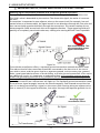
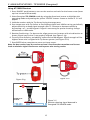
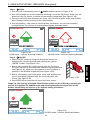
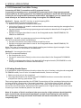
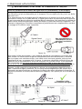
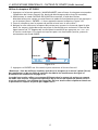
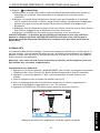
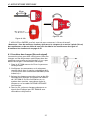
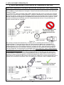
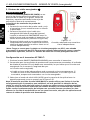
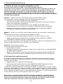
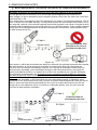
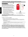
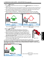
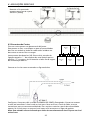
• �IMPORTANT NOTICE, PLEASE READ BEFORE YOU START TRACING
Avoiding signal cancellation problems with a separate ground connection
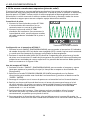
The signal generated by the transmitter creates an electromagnetic field around the wire.
This field is what is detectable by the receiver. The clearer this signal, the easier it is to trace
the wire.
If transmitter is connected to two adjacent wires on the same circuit (for example, hot and
neutral wires on a Romax cable), the signal travels in one directions through the first wire and
then returns (with opposite direction) through the second one. This causes creation of two
electromagnetic fields around each wire with opposite direction. These opposing fields will
partially or completely cancel each other out, making wire tracing difficult if not impossible.
Not recommended. This
wire connection causes
signal cancellation
AT-7000-R
AT-7000-TFigure 3a
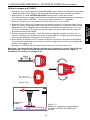
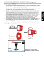
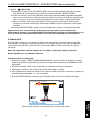
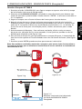
To avoid the cancellation effect, a separate ground connection method should be used.
The red test lead of the transmitter should be connected to the hot wire of the circuit
you wish to trace, and the green lead to a separate ground, such as water pipe, ground
stake, metal grounded structure of the building, or outlet ground connection of an outlet
on a different circuit. It is important to understand that an acceptable separate ground
is NOT the grounding terminal of any receptacle on the same circuit as the wire you wish
to trace. If hot wire is energized and the transmitter is properly connected to a separate
ground, the red LED on a transmitter will light up. The separate ground connection create
the maximum signal strength, because the electromagnetic field created around the hot
wire is not being cancelled by a signal on the return path flowing along an adjacent wire
(hot or neutral) in the opposite direction, but rather through the separate ground circuit.
Avoiding signal
cancellation effect
AT-7000-R
AT-7000-T
Figure 3b
To Transformer
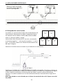
3. MAIN APPLICATIONS

12
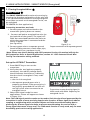
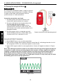
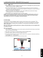
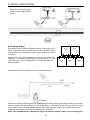
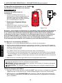
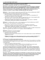
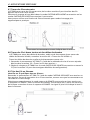
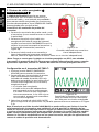
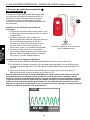
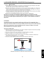
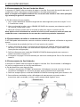
3.1 Tracing Energized Wires
SMART SENSOR
The SMART SENSOR enables easier wire tracing by
showing the direction and position of the wire and
is the recommended method for tracing energized
wires (does not work on de-energized circuits, use
de-energized
TIP SENSOR for that application).
Connecting transmitter test leads
1. Connect green and red test leads to the
transmitter (polarity does not matter)
2. . Connect red lead to energized hot wire (on
the load side of the system). The signal will
ONLY be transmitted between the outlet to
which the transmitter is connected and the
source of power
(see Figure 3a).
3. Connect green wire to a separate ground
(metal building structure, metal water pipe,
or ground wire on a separate circuit).
*Note: Please note that if working with GFCI protected circuits, this method will trip the
GFCI protection. Refer to Special Applications, section 4.1 “GFCI-Protected Circuit Wire
Tracing” for alternative tracing methods.
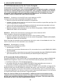
Set up the AT-7000-T Transmitter:
1. Press ON/OFF key to turn on the
transmitter.
2. Verify that the test leads are properly
connected - the red LED voltage status
should indicator should be on, indicating
that the circuit is energized. If not, make
sure that
• the circuit is energized
• the separate ground green wire is
properly grounded. If the ground wire is
not properly grounded the red LED will
not light, even when connected to an
energized circuit.
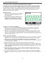
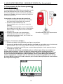
3. Select HIGH signal mode for most
applications. Screen will appear as shown
in Figure 3.1b.
Note: The LOW signal precision mode can be used to limit the signal level generated by the
transmitter in order to more precisely pinpoint wire location. A lower signal level reduces
coupling to neighboring wires and metal objects and helps to avoid misreading due to
ghost signals. A lower signal also helps to prevent oversaturating the receiver with a
strong signal that covers a large area. The LOW mode function is rarely used, only for most
demanding precise wire tracing applications.
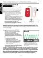
3. MAIN APPLICATIONS - SMART SENSOR (Energized)
Figure 3.1b
Transmitter screen showing signal in
HIGH mode with 6kHz frequency for
energized circuit
SMART SENSOR
Figure 3.1a
Proper connection with separate ground

13
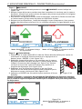
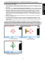
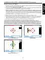
Using AT-7000-R Receiver
1. Press ‘ON/OFF’ push button to turn on the receiver and wait for the home screen (boot
up time is around 30 seconds).
2. Select SMART SENSOR mode by using the directional arrows to highlight this operating
mode and pressing the yellow ENTER button.
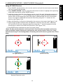
3. Hold the receiver with the Smart Sensor on the rear of the unit facing the target area.
If the screen flashes a “?” in a red target then no signal is detected. Move the Smart
Sensor closer to the target area until the signal is detected and you see a directional
arrow. If no signal is detected increase the sensitivity using the “+” button on the
receiver. (see Figure 3.1c)*
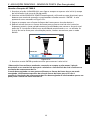
4. Move the Receiver in direction indicated by the arrow on the screen (see Figure 3.1d)
5. Green target symbol indicates that the Receiver is directly over the wire. If Receiver
will not lock on the wire, decrease sensitivity using the “-“ on the keypad or set the
transmitter to transmit at LOW level (Precision). (see Figure 3.1e)
6. Press ENTER when complete to return to Home screen.
*Note: For best results, keep the receiver at least 3 feet from the transmitter and its test
leads to minimize signal interference and improve wire tracing results. Select the “Long”
Smart Sensor Range in the Settings Menu if working with wires that are greater than 3 feet
deep.
Figure 3.1c
No signal detected
Figure 3.1d
Wire on the left
Figure 3.1e
Receiver locked on wire
3. MAIN APPLICATIONS - SMART SENSOR (Energized)
SMART SENSOR

14
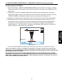
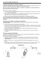
3.1 Tracing Energized Wires
TIP SENSOR
TIP SENSOR mode is used for the following
applications: pinpointing a wire in a bundle,
tracing in corners and confined spaces such as
junction boxes or inside enclosures.
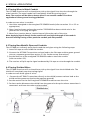
Connecting transmitter test leads
1. Connect green and red test leads to the
transmitter (polarity does not matter)
2. Connect red lead to energized hot wire (on
the load side of the system).
The signal will ONLY be transmitted between
the outlet to which the transmitter is
connected and the source of power (see
Figure 3b).
3. Connect green wire to a separate ground
(metal building structure, metal water pipe,
or ground wire on a separate circuit).
*Note: Please note that if working with GFCI protected circuits, this method will trip the
GFCI protection. Refer to Special Applications, section 4.1 “GFCI-Protected Circuit Wire
Tracing” for alternative tracing methods.
Set up the AT-7000-T Transmitter:
1. Press ON/OFF key to turn on the transmitter.
2. Verify that the test leads are properly connected - the red LED voltage status should
indicator should be on, indicating that the circuit is energized. If not, make sure that
• the circuit is energized
• the separate ground green wire is properly grounded. If the ground wire is not
properly grounded the red LED will not light, even when connected to an energized
circuit.
3. Select HIGH signal mode for most applications. Screen will appear as shown in Figure
3.1b.
Note: The LOW signal precision mode can be used to limit the signal level generated by the
transmitter in order to more precisely pinpoint wire location. A lower signal level reduces
coupling to neighboring wires and metal objects and helps to avoid misreading due to
ghost signals. A lower signal also helps to prevent oversaturating the receiver with a
strong signal that covers a large area. The LOW mode function is rarely used, only for most
demanding precise wire tracing applications.
3. MAIN APPLICATIONS - TIP SENSOR (Energized)
TIP SENSOR
Figure 3.1f
Proper connection with separate ground

15
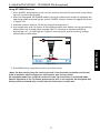
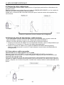
Using AT-7000-R Receiver
1. Press ‘ON/OFF’ push button to turn on the receiver and wait for the home screen (boot
up time is around 30 seconds).
2. Select Energized TIP SENSOR mode by using the directional arrows to highlight this
operating mode and pressing the yellow “ENTER” button. Screen as shown in 3.1i will
appear.
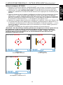
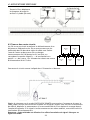
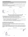
3. Hold the receiver with the Tip Sensor facing the target area.
4. Scan target area with Tip Sensor to find highest signal level. While tracing, periodically
adjust sensitivity to keep signal strength near 75. Increase or decrease sensitivity
by pressing + or – on the keypad. If signal is too strong for precise locating, change
transmitter to LOW mode.
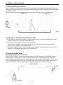
5. Receiver Positioning: For best results, align groove on tip sensor with wire direction as
shown. Signal may be lost if not properly aligned. (see Figure 3.1g)
6. To verify wire direction, periodically rotate receiver 90 degrees. Signal strength will be
highest when wire is aligned with Tip Sensor groove. (see Figure 3.1h)
7. Press ENTER when complete to return to Home screen.
Note: For best results, keep the receiver at least 3 feet from the transmitter and its test
leads to minimize signal interference and improve wire tracing results.
Figure 3.1g
Figure 3.1h
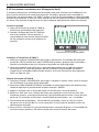
Figure 3.1i
Receiver showing signal detected in
Energized TIP SENSOR mode
30-600V AC/DC
40-400 HZ
TIP SENSOR ENERGIZED
-
-
75
SIGNAL
3. MAIN APPLICATIONS - TIP SENSOR (Energized)
TIP SENSOR

16
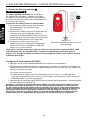
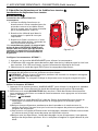
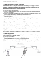
3.2 Tracing De-energized Wires
TIP SENSOR
De-energized TIP SENSOR mode is used for general
wire tracing, pinpointing wires in bundles, tracing
in tight corners and confined spaces such as
junction boxes or inside enclosures.
Connecting transmitter test leads
1. Connect green and red test leads to the
transmitter (polarity does not matter)
2. Connect red lead to de-energized hot wire
(on the load side of the system).
In de-energized mode the signal will be
injected to ALL branches of the circuit, not
just between the outlet and the breaker as in
energized modes.
3. Connect green wire to a separate ground
(metal building structure, metal water pipe,
or ground wire on a separate circuit).
Set up the AT-7000-T Transmitter:
1. Press ON/OFF key to turn on the transmitter.
2. The red LED voltage status should indicator should be off, indicating that the circuit is
de-energized. If LED is on, disconnect power to the circuit.
3. Select HIGH signal mode for most applications. Screen will appear as shown in Figure
3.2b
Note: The LOW signal precision mode can be used to limit the signal level generated by the
transmitter in order to more precisely pinpoint wire location. A lower signal level reduces
coupling to neighboring wires and metal objects and helps to avoid misreading due to
ghost signals. A lower signal also helps to prevent oversaturating the receiver with a
strong signal that covers a large area. The LOW mode function is rarely used, only for most
demanding precise wire tracing applications.
HIGH
0V DC
33 KHZ
Figure 3.2b
3. MAIN APPLICATIONS - TIP SENSOR (De-Energized)
TIP SENSOR
Figure 3.2a
Proper connection with separate ground
La page est en cours de chargement...
La page est en cours de chargement...
La page est en cours de chargement...
La page est en cours de chargement...
La page est en cours de chargement...
La page est en cours de chargement...
La page est en cours de chargement...
La page est en cours de chargement...
La page est en cours de chargement...
La page est en cours de chargement...
La page est en cours de chargement...
La page est en cours de chargement...
La page est en cours de chargement...
La page est en cours de chargement...
La page est en cours de chargement...
La page est en cours de chargement...
La page est en cours de chargement...
La page est en cours de chargement...
La page est en cours de chargement...
La page est en cours de chargement...
La page est en cours de chargement...
La page est en cours de chargement...
La page est en cours de chargement...
La page est en cours de chargement...
La page est en cours de chargement...
La page est en cours de chargement...
La page est en cours de chargement...
La page est en cours de chargement...
La page est en cours de chargement...
La page est en cours de chargement...
La page est en cours de chargement...
La page est en cours de chargement...
La page est en cours de chargement...
La page est en cours de chargement...
La page est en cours de chargement...
La page est en cours de chargement...
La page est en cours de chargement...
La page est en cours de chargement...
La page est en cours de chargement...
La page est en cours de chargement...
La page est en cours de chargement...
La page est en cours de chargement...
La page est en cours de chargement...
La page est en cours de chargement...
La page est en cours de chargement...
La page est en cours de chargement...
La page est en cours de chargement...
La page est en cours de chargement...
La page est en cours de chargement...
La page est en cours de chargement...
La page est en cours de chargement...
La page est en cours de chargement...
La page est en cours de chargement...
La page est en cours de chargement...
La page est en cours de chargement...
La page est en cours de chargement...
La page est en cours de chargement...
La page est en cours de chargement...
La page est en cours de chargement...
La page est en cours de chargement...
La page est en cours de chargement...
La page est en cours de chargement...
La page est en cours de chargement...
La page est en cours de chargement...
La page est en cours de chargement...
La page est en cours de chargement...
La page est en cours de chargement...
La page est en cours de chargement...
La page est en cours de chargement...
La page est en cours de chargement...
La page est en cours de chargement...
La page est en cours de chargement...
La page est en cours de chargement...
La page est en cours de chargement...
La page est en cours de chargement...
La page est en cours de chargement...
La page est en cours de chargement...
La page est en cours de chargement...
La page est en cours de chargement...
La page est en cours de chargement...
La page est en cours de chargement...
La page est en cours de chargement...
La page est en cours de chargement...
La page est en cours de chargement...
La page est en cours de chargement...
La page est en cours de chargement...
La page est en cours de chargement...
La page est en cours de chargement...
La page est en cours de chargement...
La page est en cours de chargement...
La page est en cours de chargement...
La page est en cours de chargement...
La page est en cours de chargement...
La page est en cours de chargement...
La page est en cours de chargement...
La page est en cours de chargement...
La page est en cours de chargement...
La page est en cours de chargement...
La page est en cours de chargement...
La page est en cours de chargement...
La page est en cours de chargement...
La page est en cours de chargement...
La page est en cours de chargement...
La page est en cours de chargement...
La page est en cours de chargement...
La page est en cours de chargement...
La page est en cours de chargement...
La page est en cours de chargement...
La page est en cours de chargement...
La page est en cours de chargement...
La page est en cours de chargement...
La page est en cours de chargement...
La page est en cours de chargement...
La page est en cours de chargement...
La page est en cours de chargement...
La page est en cours de chargement...
La page est en cours de chargement...
La page est en cours de chargement...
La page est en cours de chargement...
La page est en cours de chargement...
La page est en cours de chargement...
La page est en cours de chargement...
La page est en cours de chargement...
La page est en cours de chargement...
La page est en cours de chargement...
La page est en cours de chargement...
-
 1
1
-
 2
2
-
 3
3
-
 4
4
-
 5
5
-
 6
6
-
 7
7
-
 8
8
-
 9
9
-
 10
10
-
 11
11
-
 12
12
-
 13
13
-
 14
14
-
 15
15
-
 16
16
-
 17
17
-
 18
18
-
 19
19
-
 20
20
-
 21
21
-
 22
22
-
 23
23
-
 24
24
-
 25
25
-
 26
26
-
 27
27
-
 28
28
-
 29
29
-
 30
30
-
 31
31
-
 32
32
-
 33
33
-
 34
34
-
 35
35
-
 36
36
-
 37
37
-
 38
38
-
 39
39
-
 40
40
-
 41
41
-
 42
42
-
 43
43
-
 44
44
-
 45
45
-
 46
46
-
 47
47
-
 48
48
-
 49
49
-
 50
50
-
 51
51
-
 52
52
-
 53
53
-
 54
54
-
 55
55
-
 56
56
-
 57
57
-
 58
58
-
 59
59
-
 60
60
-
 61
61
-
 62
62
-
 63
63
-
 64
64
-
 65
65
-
 66
66
-
 67
67
-
 68
68
-
 69
69
-
 70
70
-
 71
71
-
 72
72
-
 73
73
-
 74
74
-
 75
75
-
 76
76
-
 77
77
-
 78
78
-
 79
79
-
 80
80
-
 81
81
-
 82
82
-
 83
83
-
 84
84
-
 85
85
-
 86
86
-
 87
87
-
 88
88
-
 89
89
-
 90
90
-
 91
91
-
 92
92
-
 93
93
-
 94
94
-
 95
95
-
 96
96
-
 97
97
-
 98
98
-
 99
99
-
 100
100
-
 101
101
-
 102
102
-
 103
103
-
 104
104
-
 105
105
-
 106
106
-
 107
107
-
 108
108
-
 109
109
-
 110
110
-
 111
111
-
 112
112
-
 113
113
-
 114
114
-
 115
115
-
 116
116
-
 117
117
-
 118
118
-
 119
119
-
 120
120
-
 121
121
-
 122
122
-
 123
123
-
 124
124
-
 125
125
-
 126
126
-
 127
127
-
 128
128
-
 129
129
-
 130
130
-
 131
131
-
 132
132
-
 133
133
-
 134
134
-
 135
135
-
 136
136
-
 137
137
-
 138
138
-
 139
139
-
 140
140
-
 141
141
-
 142
142
-
 143
143
-
 144
144
-
 145
145
-
 146
146


Amprobe AT-7020 & AT-7030 Manuel utilisateur
- Taper
- Manuel utilisateur
dans d''autres langues
Documents connexes
-
Ampro AT-6010-R Manuel utilisateur
-
Amprobe AT-6000 Manuel utilisateur
-
Amprobe Kit localizador de cables avanzado AT-8030 de Amprobe Manuel utilisateur
-
Amprobe Models: Amprobe AT-8020 Advanced Wire Tracer Kit Mode d'emploi
-
Amprobe UAT-610 & UAT-620 Manuel utilisateur
-
-
-
-
-
Autres documents
-
 Beha-Amprobe AT-7000-EUR Manuel utilisateur
-
Ideal 61-957 Manuel utilisateur
-
 Sperry instruments ET65220 Le manuel du propriétaire
-
Klein Tools M2O41518KIT Manuel utilisateur
-
IDEAL INDUSTRIES 61-534 Guide d'installation
-
Ideal 61-534 Mode d'emploi
-
Ryobi ESV1000 Le manuel du propriétaire
-
koban KCL-01 Manuel utilisateur
-
Sperry PD6902-C Manuel utilisateur
-

