Amprobe AF-600 A-Frame Manuel utilisateur
- Taper
- Manuel utilisateur

User Manual
ENG FRE
SPA
AF-600
A-Frame cable ground fault finder


AF-600
A-Frame cable ground fault finder
User Manual
11/2018, 6011224 B
©2018 Amprobe
All rights reserved. Printed in China
English

Limited Warranty and Limitation of Liability
Your Amprobe product will be free from defects in material and workmanship for one year from the date
of purchase unless local laws require otherwise. This warranty does not cover fuses, disposable batteries or
damage from accident, neglect, misuse, alteration, contamination, or abnormal conditions of operation or
handling. Resellers are not authorized to extend any other warranty on the behalf of Amprobe. To obtain
service during the warranty period, return the product with proof of purchase to an authorized Amprobe
Service Center or to an Amprobe dealer or distributor. See Repair Section for details. THIS WARRANTY IS YOUR
ONLY REMEDY. ALL OTHER WARRANTIES - WHETHER EXPRESS, IMPLIED OR STATUTORY - INCLUDING IMPLIED
WARRANTIES OF FITNESS FOR A PARTICULAR PURPOSE OR MERCHANTABILITY, ARE HEREBY DISCLAIMED.
MANUFACTURER SHALL NOT BE LIABLE FOR ANY SPECIAL, INDIRECT, INCIDENTAL OR CONSEQUENTIAL
DAMAGES OR LOSSES, ARISING FROM ANY CAUSE OR THEORY. Since some states or countries do not allow
the exclusion or limitation of an implied warranty or of incidental or consequential damages, this limitation of
liability may not apply to you.
Repair
All Amprobe returned for warranty or non-warranty repair or for calibration should be accompanied by the
following: your name, company’s name, address, telephone number, and proof of purchase. Additionally,
please include a brief description of the problem or the service requested and include the test leads with the
meter. Non-warranty repair or replacement charges should be remitted in the form of a check, a money order,
credit card with expiration date, or a purchase order made payable to Amprobe.
In-warranty Repairs and Replacement – All Countries
Please read the warranty statement and check your battery before requesting repair. During the warranty
period, any defective test tool can be returned to your Amprobe distributor for an exchange for the same
or like product. Please check the “Where to Buy” section on amprobe.com for a list of distributors near you.
Additionally, in the United States and Canada, in-warranty repair and replacement units can also be sent to an
Amprobe Service Center (see address below).
Non-warranty Repairs and Replacement – United States and Canada
Non-warranty repairs in the United States and Canada should be sent to an Amprobe Service Center. Call
Amprobe or inquire at your point of purchase for current repair and replacement rates.
USA: Canada:
Amprobe Amprobe
Everett, WA 98203 Mississauga, ON L4Z 1X9
Tel: 877-AMPROBE (267-7623) Tel: 905-890-7600
Non-warranty Repairs and Replacement – Europe
European non-warranty units can be replaced by your Beha-Amprobe distributor for a nominal charge. Please
check the “Where to Buy” section on beha-amprobe.com for a list of distributors near you.
Beha-Amprobe
Division and reg. trademark of Fluke Corp. (USA)
Germany* United Kingdom The Netherlands - Headquarters**
In den Engematten 14 52 Hurricane Way Science Park Eindhoven 5110
79286 Glottertal Norwich, Norfolk 5692 EC Son
Germany NR6 6JB United Kingdom The Netherlands
Phone: +49 (0) 7684 8009 - 0 Phone: +44 (0) 1603 25 6662 Phone: +31 (0) 40 267 51 00
beha-amprobe.de beha-amprobe.com beha-amprobe.com
*(Correspondence only – no repair or replacement available from this address. European customers please
contact your distributor.)
**single contact address in EEA Fluke Europe BV

1
AF-600 A-Frame cable ground fault finder
CONTENTS
1. PRECAUTIONS AND SAFETY MEASURES ...................................................................2
2. INTRODUCTION ...........................................................................................................3
3. OPERATION ................................................................................................................. 3
4. FAULT LOCATE SCREEN ..............................................................................................
4
5. UAT-600-T TRANSMITTER ............................................................................................ 4
5.1 Transmitter Display ............................................................................................................... 4
5.2 Transmitter Controls and Connections ................................................................................ 4
6. USING THE A-FRAME TO PINPOINT A FAULT .............................................................5
6.1 Preparing a Cable ................................................................................................................. 5
6.2 Connecting the UAT-600-T Transmitter ............................................................................... 6
6.3 Pinpointing the Fault with the A-Frame ............................................................................. 7
7. BATTERY REPLACEMENT ............................................................................................. 9
8. SPECIFICATIONS ...........................................................................................................10

2
1. PRECAUTIONS AND SAFETY MEASURES
SYMBOLS
Caution! Refer to the explanation in this manual.
WARNING HAZARDOUS VOLTAGE. Risk of electric shock.
Consult user documentation.
The equipment is protected by double insulation or reinforced insulation.
Battery.
®
Certified by CSA Group to North American safety standards.
Complies with European Directives.
Conforms to relevant South Korean EMC Standards.
Conforms to relevant Australian standards.
This product complies with the WEEE Directive marking requirements. The affixed label indicates
that you must not discard this electrical/electronic product in domestic household waste. Product
Category: With reference to the equipment types in the WEEE Directive Annex I, this product is
classed as category 9 “Monitoring and Control Instrumentation” product. Do not dispose of this
product as unsorted municipal waste.
SAFETY INFORMATION
The product complies with:
• UL/IEC 61010-1, CAN/CSA C22.2 No. 61010-1, Pollution Degree 2
• EMC IEC 61326-1
CENELEC Directives
The instrument conforms to CENELEC Low-voltage directive 2014/35/EU and Electromagnetic compatibility
directive 2014/30/EU.
Warnings: Read Before Using
To avoid the possibility of electric shock or personal injury:
• Use the Product only as specified in this manual or the protection provided by the instrument may be
compromised.
• Avoid working alone so assistance can be rendered.
• Test on a known signal source within the rated voltage range of the Product both before and after use to
ensure the Product is in good working conditions.
• Do not use the Product around explosive gas, vapor, or in damp or wet environments that exceed IP54
rating. This Product meets water and dust protection IP 54 per IEC 60529.
• Inspect the Product before use and do not use if it appears damaged. Check for cracks or missing plastic.
Pay particular attention to the insulation around the connectors.
• Inspect the earth spike and product body insulation (fiber glass and plastics) before use. Do not use if
insulation is damaged.
• A-Frame is to be used with UAT-600-T Transmitter. Check all safety information in UAT-600 User Manual before use.
• Do not use the Product if it operates incorrectly. Protection may be impaired. When in doubt, have the
Product serviced.
• Have the Product serviced only by qualified service personnel.
• Use extreme caution when working around bare conductors or bus bars. Contact with the conductor could
result in electric shock.
• Do not hold the Product beyond the tactile barrier.

3
• Remove the Product from measuring position before opening the Product case or battery cover.
• Never operate the Product with the battery cover removed or the case open.
• Use caution when working with voltages above 30 V AC RMS, 42 V AC peak, or 60 V DC. These voltages
pose a shock hazard.
• Do not attempt to connect to any circuit carrying voltage.
• To avoid false readings that can lead to electrical shock and/or injury, replace the batteries as soon as the
low battery indicator appears. Check Product operation on a known source before and after use.
• Use only 6 x AA batteries properly installed in the battery compartment, to power the Product
(see Section 7: BATTERY REPLACEMENT).
• When servicing, use only specified user serviceable replacement parts.
• Adhere to local and national safety codes. Individual protective equipment must be used to prevent shock
and arc blast injury where hazardous live conductors are exposed.
• For use by competent persons only.
• Remove the batteries if the Product is not used for an extended period of time, or if stored in temperatures
above 140 °F (60 °C). If the batteries are not removed, battery leakage can damage the Product.
• Follow all battery care from the battery manufacturer.
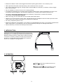
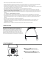
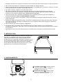
2. INTRODUCTION
The AF-600 A-Frame cable ground fault finder is an
optional accessory specifically designed for the Amprobe
UAT-600 series. In combination with the Transmitter, it will
pinpoint the place where a cable metal conductor (either
a sheath or a metallic conductor of the wire) touches the
ground. It can also detect other conductors to ground
faults such as pipeline coating defects.
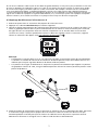
3. OPERATION
1
On/off
: Press for 2 seconds to turn on or
turn off the A-Frame.
2
Speaker Volume :
Press repeatedly to loop
between mute and three levels of volume.
29
L H
1
2

4
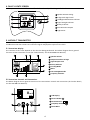
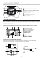
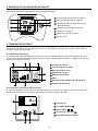
4. FAULT LOCATE SCREEN
A short press on the On/Off button will switch on the unit, defaulting to the Fault Locate screen.
1
Speaker Volume Setting
2
2-digit Fault Signal Level
3
Left/Right Cable Position Indicator
4
Signal Strength Indicator
5
Battery Indicator
6
Fault Direction Compass
7
Light Sensor
29
L H
1
2
3
4
5
6
7
5. UAT-600-T TRANSMITTER
The UAT-600-T Transmitter is used to apply a fault find signal to the utility under test. Use the Transmitter in
combination with the A-Frame to receive the signal and pinpoint a place of the fault.
5.1 Transmitter Display
The contents of the screen depend on the function being performed. The below diagram shows general
functions of the Transmitter screen (for further details, see the UAT-600 User Manual).
1 Speaker Volume
Output Hazardous Voltage
Signal Output Level
Battery Indicator
Locating Mode
Menu
Gain Setting Reminder
Frequency Selection
5
4
3
2
6
7
5
78
Tx
4
31
6
2
8
5.2 Transmitter Controls and Connections
The below diagram shows general functions of the Transmitter controls and connections (for further details,
see the UAT-600 User Manual).
1
LCD Display
2
Power ON/OFF
3
Down/Decrease
/
4
Frequency Selection
5
Enter/Menu
ENTER
0 m A
mA
2
5
43
1

5
Use caution when above voltage indication warnings are ON.
6 Terminals for direct connection and signal clamp
Tx
Hazardous output voltage indicator.
The icon on the screen indicates the transmitter is
outputting voltages ≥30 V.
Protection fuse
Hazardous voltage indicator (over 30 V)
The red solid light indicates the presence of AC voltage ≥30 V
on the circuit under direct connection mode.
The red blinking light indicates the presence of voltages
above 30 V on the Transmitter terminals under A-Lo and A-Hi
mode (generated and/or measured). In case of the presence
of line voltage >50 V (typical) during the operation of A-Lo or
A-Hi mode, the transmitter automatically disables A-Lo and
A-Hi modes, the red solid light indicator appears.
Always check the presence of voltage on the circuit by
additional voltage tester.
7
8
9
9
6
87
Tx
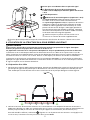
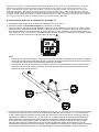
6. USING THE A-FRAME TO PINPOINT A FAULT
WARNING
Always be aware of the location of buried utilities (especially buried power lines) when pushing the spikes of
the A-Frame into the soil.
The spikes of the A-Frame are sharp. Always handle carefully to avoid injury.
The A-Frame is used to detect ground faults on cables and pipes. In the case of cables, faults are usually
caused by insulation damage allowing the metallic sheath or internal conductor to become in contact with the
ground. In the case of pipes, the faults consist of coating defects.
The A-Frame works in conjunction with the UAT-600-T Transmitter. The Transmitter is used to apply a fault find
signal to the utility under test, and the A-Frame is used to receive the signal and pinpoint a place of the fault.
6.1 Preparing a Cable
1. Disconnect and isolate the cable on both ends. Make sure to disconnect all ground bonding. This will ensure
that the test signal traveling through the ground fault is not masked or doesn’t interfere with the one
conducted by grounding bonding to the ground. The A-Frame cannot distinguish between these two signals.
2. Use the resistance measuring function on the Transmitter, or a dedicated resistance measuring device, to
identify a cable with a fault to ground. The A-Frame will typically detect faults up to 2 MΩ (depending on
the distance from the Transmitter, soil conditions, etc.).
When at A-Lo / A-Hi mode, the
indicator will blink. In case of a voltage presence ≥10 V (typical) on the
circuit under test, the Ω measurement will be opt out under MENU screen.

6
3. Optionally, you can precisely detect and mark cable locations using the UAT-600-R receiver. Refer to the
UAT-600 User Manual for detailed instructions how to locate underground utilities.
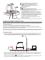
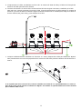
6.2 Connecting the UAT-600-T Transmitter
Warnings: Read Before Using
• Use the UAT-600-T Transmitter only as specified in UAT-600 User Manual or the protection provided by the
instrument may be compromised.
• Check and read all safety information in UAT-600 User Manual before use.
• Inspect the test leads before use. Do not use if insulation is damaged or metal is exposed.
• Check the test leads for continuity. Replace damaged test leads before using the Product.
• Never operate the Product with the battery cover removed or the case open.
• Use extreme caution when working around bare conductors or bus bars. Contact with the conductor could
result in electric shock.
• Disconnect and isolate the cable on both ends before connecting the UAT-600-T to the cable.
Setting up the Transmitter
1. Turn the Transmitter on by pressing power button for 2 seconds.
2. Connect the black and red test leads to the Transmitter inputs. The Transmitter will switch automatically to
Direct Connection Mode and the display will show the direct connection icon
.
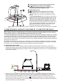
3. Insert the ground stake into the ground a few yards away, perpendicular to the line. Connect the black lead
to the ground stake with an alligator clip.
4. Connect a red test lead to the target line.
5. Pres Hz button repeatedly to select “A-LO” (A-Frame low signal) or “A-Hi” (A-Frame high signal). Use “A-
LO” for higher accuracy pinpointing. Use the “A-Hi” setting if the line to be surveyed is long or the fault
resistance is high.
6. Press the “+/-” buttons to set the output to level one. Increase the level if the resulting signal strength is
poor. Increasing the signal unnecessarily may result in the signal “bleeding off” onto other services and
creating misleading “ghost” signals. It will also drain more power from the battery.
Note: When connected, the Transmitter will emit a beep tone. The better the connection to the line and
ground, the faster the beep tone will be. Check for a good connection by disconnecting and then reconnecting
the red lead. It is also possible to check the signal current being supplied by the Transmitter by entering the
user menu and selecting the mA option.
Things that can affect the quality of connection are a rusty pipe connection point (clean the connection area
with a wire brush) or poor grounding. To improve the connection quality due to poor grounding, try inserting
the stake into damp ground. If necessary, dampen the surrounding ground with water. If grounding is still an
issue, try connecting test lead to a manhole cover surround. Avoid connecting to fence railings as these may
create return signal currents along the fencing that will interfere with the locating signal.
Note: If the signal level bars do not fill, this indicates that the impedance of the line is limiting the current
output. Increasing the output beyond this point will not increase the signal. If more signal is required, check
the quality of the connection to the line and ground.
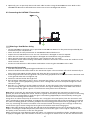
When connecting to large diameter pipes and cables, it is sometimes not possible to find a suitable projection
to apply the alligator clip. If the material is ferrous, use a magnet to make contact to the line and then attach

7
the alligator clip to a magnet. For example: making a connection to a street lighting circuit. Usually it is
practice to connect the sheath of a lighting cable to the metallic inspection cover of a street lamp. Making a
connection to the inspection plate will induce a signal to the cable via the plate and sheath. Usually, there is
no projection on the plate on which to clip so using a magnet on the plate provides a suitable clipping point.
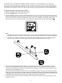
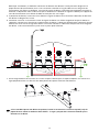
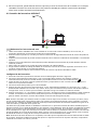
6.3 Pinpointing the Fault with the A-Frame
1. Remove the rubber spike covers from the A-Frame.
2. Press the On/Off button to turn the unit on.
3. Use the Left/Right indicator arrows to position A-Frame over the cable. At that point, the bar graph at the
bottom of the display will show maximum value for the test signal strength. The speaker will emit a pulsed
tone on one side of the cable and a solid tone on the other, so it is possible to locate the cable without
looking at the screen. If necessary, adjust the volume by using short presses on the speaker button
.
29
L H
Note:
• If the spikes are not in the ground or there is only a very low signal, the 2-digit Fault Signal Level reading and
Fault Direction Compass arrow may not be visible. These are only shown when there is a valid fault find signal.
• If the position of the line is different when comparing the Left/Right position to the peak bar graph
position, there could be a distorted signal that may affect readings. Proceed with caution.
29
L H
29
L H
29
L H
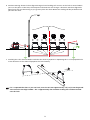
4. Start near the Transmitter. Hold the A-Frame in line with the route of the cable. Walk along the route
of the line placing the spikes of the A-Frame in the ground every two or three paces. Allow a couple of
seconds for the readings to settle before moving to the next position. Keep the A-Frame aligned with the
cable by using the Left/Right arrows.
Note: Initially, the Fault Direction Compass arrow on the display may point towards the Transmitter grounding
stake, but as you continue walking along the cable away from the Transmitter it will fluctuate or disappear. The
2-digit Fault Signal Level may also continue decreasing or disappear. This is because the A-Frame detects signals
conducted by the Transmitter ground stake and a cable fault is further along the line.
5. In proximity of the fault, the A-Frame will detect the fault signal and the Fault Direction Compass arrow
will point forward.

8
6. Continue moving forward. The 2-digit Fault Signal Level reading will increase as the fault is neared. When
you cross the place of the fault, the Compass Fault Detection will change a direction and the 2-digit Fault
Signal level will start decreasing as you go away from the fault. Maximum reading will be just before and
just after the fault.
29
L H
78
L H
78
L H
29
L H
7. Carefully place the A-Frame before and after the fault to pinpoint it. Repeating this in a line perpendicular
to the direction of the cable will pinpoint the fault laterally.
If it is suspected that there is just one fault, insert the A-frame approximately 3 ft (1 m) from the ground
stake. Note the two digit number - this is approximately the maximum reading that will be measured
over the fault.

9
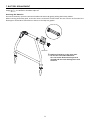
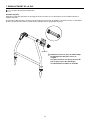
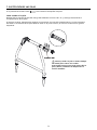
7. BATTERY REPLACEMENT
The unit is powered by six AA alkaline batteries (included). When the battery indicator on the screen indicates
empty , the batteries should be replaced.
Accessing the Batteries
Unscrew the battery cap on the A-Frame handle and remove by gently pulling the battery holder.
When inserting the battery pack, ensure the correct orientation of the holder. The two contacts at the end of the
battery pack should be at the bottom as shown in the adjacent graphic.
AA Batteries
Replace all batteries at the same time.
Do not mix new and old batteries.
This can lead to batteries being reverse
charged and can cause damage, heat and
even fire.

10
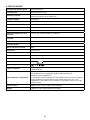
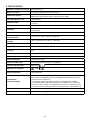
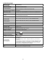
8. SPECIFICATIONS
Tracing mode (de-energized) 8 kHz (8,192 Hz)
Locating mode Ground fault locating
Sensitivity (typical)
Cable locate mode at 1 meter depth: 10 uA
Fault locate mode: up to 2 MΩ fault
Display backlight Automatic
Audio indication Speaker indicates left/right by pulsed/continuous tone
Compatible transmitter UAT-600-T Transmitter
Display 1.28 in (33 mm) 128 x 128 BW outdoor LCD display with auto backlight
Update rate Instantaneous
Operating temperature and
humidity
-4 °F to 122 °F (-20 °C to 50 °C), ≤90% RH
Storage temperature and
humidity
-40 °F to 140 °F (-40 °C to 60 °C), ≤90% RH
Operating altitude < 6561 ft (< 2000 m)
Pollution degree 2
Water and dust resistance IP54
Drop proof 3.28 ft (1 m)
Power supply Six (6) 1.5 V AA alkaline batteries
Auto power off 15 minutes idle
Battery life Approx. 60 hours at 70 °F (21 °C) (Typical)
Low battery indication
Blinking
Agency approval
®
Safety compliance
IEC 61010-1
CSA/UL 61010-1
Electromagnetic Compatibility
IEC 61326-1
Korea (KCC): Class A Equipment (Industrial Broadcasting &
Communication Equipment)
[1]
[1]
This product meets requirements for industrial (Class A) electromagnetic
wave equipment and the seller or user should take notice of it. This
equipment is intended for use in business environments and is not to be
used in homes.
Size (H x W x L) Approx. 14 x 9 x 4.7 in (355 x 230 x 120 mm)
Weight Approx. 4.2 lb (1.9 kg) (batteries installed)

AF-600
Détecteur de défauts de mise à la
terre de câbles Structure en A
Manuel de l’utilisateur
11/2018, 6011224 B
©2018 Amprobe
Tous droits réservés. Imprimé en Chine
Français

Garantie limitée et limitation de responsabilité
Votre produit Amprobe sera exempt de défauts de matériaux et de fabrication pendant un (1) an à compter
de la date d'achat, sauf exigence contraire en vertu de la juridiction locale. Cette garantie ne s'applique pas
aux fusibles, aux piles jetables ou endommagées par accident, à la négligence, à la mauvaise utilisation, à
l'altération, à la contamination ou aux conditions anormales d'utilisation ou de manipulation. Les revendeurs
ne sont pas autorisés à prolonger toute autre garantie au nom de Amprobe. Pour une réparation au cours
de la période de garantie, retournez le produit avec la preuve d'achat à un centre de service autorisé par
Amprobe ou à un revendeur ou un distributeur Amprobe. Voir la section Réparation pour plus de détails.
CETTE GARANTIE EST VOTRE SEUL RECOURS. TOUTES LES AUTRES GARANTIES – QU'ELLES SOIENT EXPLICITES,
IMPLICITES OU JURIDIQUES – Y COMPRIS LES GARANTIES IMPLICITES D'ADAPTATION À UN USAGE PARTICULIER
OU MARCHAND, SONT EXCLUES. LE FABRICANT NE SERA PAS RESPONSABLE DES DOMMAGES SPECIAUX,
INDIRECTS, ACCESSOIRES OU CONSECUTIFS PROVENANT DE TOUTE CAUSE OU THEORIE. Etant donné que
certains pays ou états n'autorisent pas l'exclusion ou la limitation des garanties implicites ou des dommages
directs ou indirects, cette limitation de responsabilité peut ne pas s'appliquer à vous.
Réparation
Tous les produits Amprobe retournés pour réparation sous garantie ou hors garantie ou pour étalonnage
doivent être accompagnés de ce qui suit: votre nom, le nom de votre société, votre adresse, votre numéro
de téléphone et la preuve d'achat. De plus, veuillez inclure une brève description du problème ou du service
demandé et incluez les cordons de mesure avec le compteur. Les frais de réparation ou de remplacement non
garantis doivent être réglés sous forme de chèque, mandat, carte de crédit avec date d'expiration ou bon de
commande payable à Amprobe.
Réparations et remplacement couverts par la garantie – Tous les pays
Veuillez lire la déclaration de garantie et vérifier la pile avant de demander une réparation. Pendant la
période de garantie, tout outil de vérification défectueux peut être retourné à votre distributeur Amprobe
pour un échange de produit identique ou similaire. Veuillez consulter la section «Où acheter» sur le site
amprobe.com pour obtenir une liste des distributeurs près de chez vous. En outre, aux États-Unis et au Canada,
les réparations sous garantie et les unités de remplacement peuvent également être envoyés à un centre de
service Amprobe (voir adresse ci-dessous).
Réparation et remplacement non couverts par la garantie – États-Unis et Canada
Pour les réparations non couvertes par la garantie aux États-Unis et au Canada, l'appareil doit être envoyé à
un centre de service Amprobe. Appelez Amprobe ou renseignez-vous auprès de votre point de vente pour les
tarifs de réparation et de remplacement actuels.
États-Unis: Canada:
Amprobe Amprobe
Everett, WA 98203 Mississauga, ON L4Z 1X9
Tél: 877-AMPROBE (267-7623) Tél.: 905-890-7600
Réparation et remplacement non couverts par la garantie – Europe
Les unités hors garantie européenne peuvent être remplacées par votre distributeur Amprobe/Beha-Amprobe
pour une somme modique. Veuillez consulter la section «Où acheter» sur le site beha-amprobe.com pour
obtenir une liste des distributeurs près de chez vous.
Beha-Amprobe
Division et marque déposée de Fluke Corp. (USA)
Allemagne* Royaume-Uni Pays-Bas - Siège social**
In den Engematten 14 52 Hurricane Way Science Park Eindhoven 5110
79286 Glottertal Norwich, Norfolk 5692 EC Son
Allemagne NR6 6JB Royaume-Uni Pays-Bas
Téléphone : +49 (0) 7684 8009 - 0 Téléphone: +44 (0) 1603 25 6662 Téléphone: +31 (0) 40 267 51 00
beha-amprobe.de beha-amprobe.com beha-amprobe.com
*(Correspondance uniquement: aucune réparation ou remplacement à cette adresse. Clients européens, veuil-
lez contacter votre distributeur.)
**adresse de contact unique dans l'EEE Fluke Europe BV

1
Détecteur de défauts de mise à la terre de câbles
Structure en A AF-600
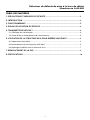
TABLE DES MATIÈRES
1. PRÉCAUTIONS ET MESURES DE SÉCURITÉ ................................................................. 2
2. INTRODUCTION ...........................................................................................................3
3. FONCTIONNEMENT ....................................................................................................3
4. ÉCRAN LOCALISATION DE DÉFAUTS .........................................................................
4
5. TRANSMETTEUR UAT-600-T ........................................................................................4
5.1 Affichage du transmetteur ..................................................................................................4
5.2 Commandes et raccordements du transmetteur ................................................................ 4
6. UTILISATION DE LA STRUCTURE EN A POUR REPÉRER UN DÉFAUT .........................5
6.1 Préparation d'un câble .........................................................................................................5
6.2 Raccordement du transmetteur UAT-600-T......................................................................... 6
6.3 Repérage du défaut avec la Structure en A ........................................................................7
7. REMPLACEMENT DE LA PILE .......................................................................................9
8. SPÉCIFICATIONS ...........................................................................................................10

2
1. PRÉCAUTIONS ET MESURES DE SÉCURITÉ
SYMBOLES
Attention! Reportez-vous aux explications de ce guide.
AVERTISSEMENT TENSION DANGEREUSE. Risque de choc électrique.
Consultez la documentation de l'utilisateur.
Cet équipement est protégé par une isolation double ou renforcée.
Pile.
®
Certifié par le Groupe CSA selon les normes de sécurité d'Amérique du Nord.
Conforme aux directives européennes.
Conforme aux normes relatives aux CEM applicables en Corée du Sud.
Conforme aux normes australiennes.
Ce produit est conforme aux exigences de marquage de la directive DEEE. L'étiquette apposée
indique que vous ne devez pas jeter ce produit électrique/électronique avec les déchets ménagers.
Catégorie du produit: Concernant les types d'équipements de l'Annexe I de la Directive DEEE, ce
produit est classifié en tant que produit de catégorie 9 «Instrumentation de surveillance et de
contrôle». Ne jetez pas ce produit avec les déchets municipaux non triés.
CONSIGNES DE SÉCURITÉ
Ce produit est conforme à:
• UL/IEC 61010-1, CAN/CSA C22.2 No. 61010-1, degré de pollution 2
• EMC IEC 61326-1
Directives CENELEC
L'instrument est conforme à la directive basse tension CENELEC 2014/35/UE et à la directive de compatibilité
électromagnétique 2014/30/UE.
Avertissements: Lire avant utilisation
Pour éviter la possibilité d'une électrocution ou d'une blessure:
• Utilisez le produit comme indiqué dans ce manuel, dans le cas contraire la protection fournie par
l'instrument peut être compromise.
• Évitez de travailler seul pour pouvoir bénéficier d'une assistance.
• Faites un essai sur une source de signal connue dans la plage nominale de tension du produit avant et après
utilisation pour vous assurer que le produit est en bon état de fonctionnement.
• N'utilisez pas la produit près d'environnements avec des vapeur, des gaz explosifs ou de l'humidité
dépassant l'indice IP54. Ce produit est conforme à l'indice de protection IP 54 contre l'eau et la poussière
conformément à IEC 60529.
• Inspectez le produit avant utilisation et ne l'utilisez pas s'il semble endommagé. Contrôlez la présence de
fissures ou le plastique manquant. Faites particulièrement attention à l'isolation autour des connecteurs.
• Inspectez le piquet de terre et l'isolation du corps du produit (plastique et verre plus fibre) avant utilisation.
Ne l'utilisez pas si l'isolation est endommagée.
• La Structure en A doit être utilisée avec le transmetteur UAT-600-T. Consultez toutes les informations de
sécurité dans le manuel d'utilisation UAT-600 avant utilisation.
• N'utilisez pas le produit s'il ne fonctionne pas correctement. La protection peut être altérée. En cas de
doute, faites réparer le produit.
• Seul du personnel qualifié peut se charger de l'entretien du produit.
• Utilisez avec une grande prudence lorsque vous travaillez avec des conducteurs ou barres omnibus exposés.
Le contact avec le conducteur pourrait causer une électrocution.

3
• Ne tenez pas le produit au-delà de la barrière tactile.
• Retirez le produit de la position de mesure avant d'ouvrir le boîtier ou le couvercle des piles du produit.
• N'utilisez jamais le produit lorsque le couvercle des piles est retiré ou le boîtier est ouvert.
• Faites preuve de prudence en travaillant sur des tensions supérieures à 30 V CA RMS, 42 V CA crête ou 60 V
CC. Ces tensions posent des risques d'électrocution.
• N'essayez pas d'effectuer un raccordement à un circuit conduisant une tension.
• Pour éviter les mauvaises lectures pouvant entraîner une électrocution et/ou une blessure corporelle,
remplacez les piles dès que le voyant de piles faibles s'affiche. Vérifiez le fonctionnement du produit sur
une source connue avant et après utilisation.
• Utilisez uniquement 6piles AA correctement installées dans le compartiment des piles pour alimenter le
produit
(voir Section 7: REMPLACEMENT DE LA PILE).
• Lors des réparations, n'utilisez que les pièces de rechange préconisées réparables par les utilisateurs.
• Conformez-vous aux normes locales et nationales de sécurité. De l'équipement de protection individuelle
doit être utilisé pour éviter les chocs et les blessures lorsque des conducteurs en fonctionnement sont
exposés.
• Utilisation par des personnes compétentes uniquement.
• Retirez les piles si le produit n'est pas utilisé pendant une durée prolongée ou s'il est stocké à une
température supérieure à 140 °F (60 °C). Si les piles ne sont pas retirées, une fuite des piles peut
endommager le produit.
• Respectez tous les consignes d'entretien des piles émises par le fabricant des piles.
2. INTRODUCTION
Le détecteur de défauts de mise à la terre de câbles
Structure en A AF-600 est un accessoire optionnel
spécialement conçu pour l'Amprobe série UAT-600. En
combinaison avec le transmetteur, il repère l'endroit
où un conducteur métallique de câble (une gaine ou
un conducteur métallique du fil) touche le sol. Il peut
également détecter d'autres défauts de conducteurs à la
terre, tels que des défauts de revêtement de canalisations.
3. FONCTIONNEMENT
1
Marche/arrêt
: Appuyez pendant
2secondes pour allumer ou éteindre la
Structure en A.
2
Volume du haut-parleur :
Appuyez de
manière répétée pour faire défiler le mode
muet et les trois niveaux de volume.
29
L H
1
2

4
4. ÉCRAN LOCALISATION DE DÉFAUTS
Un appui court sur le bouton Marche/Arrêt permet d'allumer l'appareil, qui accède par défaut à l'écran
Localisation de défauts.
1
Réglage du volume du haut-parleur
2
Niveau du signal du défaut à 2chiffres
3
Indicateur de position du câble Gauche/Droite
4
Indicateur d'intensité du signal
5
Indicateur des piles
6
Boussole de direction du défaut
7
Capteur de lumière
29
L H
1
2
3
4
5
6
7
5. TRANSMETTEUR UAT-600-T
Le transmetteur UAT-600-T est utilisé pour appliquer un signal de détection de défaut à l'installation testée.
Utilisez le transmetteur en association avec la Structure en A pour recevoir le signal et repérer une localisation
du défaut.
5.1 Affichage du transmetteur
Le contenu de l'écran dépend de la fonction exécutée. Le diagramme ci-dessous présente les fonctions
générales de l'écran du transmetteur (pour plus de détails, consultez le manuel d'utilisation UAT-600).
1 Volume du haut-parleur
Tension de sortie dangereuse
Niveau de sortie du signal
Indicateur des piles
Mode localisation
Menu
Rappel du réglage du gain
Sélection de fréquence
5
4
3
2
6
7
5
78
Tx
4
31
6
2
8
5.2 Commandes et raccordements du transmetteur
Le diagramme ci-dessous présente les fonctions générales des commandes et des raccordements du
transmetteur (pour plus de détails, consultez le manuel d'utilisation UAT-600).
1
Écran LCD
2
Mise sous tension/hors tension
3
Bas/Diminuer
/
4
Sélection de fréquence
5
Entrée/Menu
ENTER
0 m A
mA
2
5
43
1
La page est en cours de chargement...
La page est en cours de chargement...
La page est en cours de chargement...
La page est en cours de chargement...
La page est en cours de chargement...
La page est en cours de chargement...
La page est en cours de chargement...
La page est en cours de chargement...
La page est en cours de chargement...
La page est en cours de chargement...
La page est en cours de chargement...
La page est en cours de chargement...
La page est en cours de chargement...
La page est en cours de chargement...
La page est en cours de chargement...
La page est en cours de chargement...
La page est en cours de chargement...
La page est en cours de chargement...
La page est en cours de chargement...
La page est en cours de chargement...
-
 1
1
-
 2
2
-
 3
3
-
 4
4
-
 5
5
-
 6
6
-
 7
7
-
 8
8
-
 9
9
-
 10
10
-
 11
11
-
 12
12
-
 13
13
-
 14
14
-
 15
15
-
 16
16
-
 17
17
-
 18
18
-
 19
19
-
 20
20
-
 21
21
-
 22
22
-
 23
23
-
 24
24
-
 25
25
-
 26
26
-
 27
27
-
 28
28
-
 29
29
-
 30
30
-
 31
31
-
 32
32
-
 33
33
-
 34
34
-
 35
35
-
 36
36
-
 37
37
-
 38
38
-
 39
39
-
 40
40


Amprobe AF-600 A-Frame Manuel utilisateur
- Taper
- Manuel utilisateur
dans d''autres langues
- English: Amprobe AF-600 A-Frame User manual
- español: Amprobe AF-600 A-Frame Manual de usuario
Documents connexes
-
Amprobe BT-Series Manuel utilisateur
-
Amprobe UAT-610 & UAT-620 Manuel utilisateur
-
-
Amprobe Kit localizador de cables avanzado AT-8030 de Amprobe Manuel utilisateur
-
Ampro AT-6010-R Manuel utilisateur
-
Amprobe AT-6000 Manuel utilisateur
-
-
Amprobe ALC-110 Leakage Clamp Manuel utilisateur
-
-