Amprobe A-5000 Sheath Fault Locator Manuel utilisateur
- Taper
- Manuel utilisateur

A-5000
Sheath Fault Locator
Users Manual
Mode d’emploi•
Bedienungshandbuch•
Manuale d’Uso•
Manual de uso•
Användarhandbok•


1
English
A-5000
Sheath Fault Locator
Users Manual
A5000_Rev002
© 2009 Amprobe Test Tools.
All rights reserved.

2
Limited Warranty and Limitation of Liability
Your Amprobe product will be free from defects in material and workmanship for 1 year from the date of purchase. This
warranty does not cover fuses, disposable batteries or damage from accident, neglect, misuse, alteration, contamination, or
abnormal conditions of operation or handling. Amprobe’s warranty obligation is limited, at Amprobe’s option, to refund of
the purchase price, free of charge repair, or replacement of a defective product . Resellers are not authorized to extend any
other warranty on Amprobe’s behalf. To obtain service during the warranty period, return the product with proof of purchase
to an authorized Amprobe Test Tools Service Center or to an Amprobe dealer or distributor. See Repair Section for details. This
warranty is your only remedy . All other warranties - whether express, implied or statutory - including implied warranties of
fitness for a particular purpose or merchantability, are hereby excluded. Neither Amprobe nor its parent company or affiliates
shall be liable for any special, indirect, incidental or consequential damages or losses, arising from any cause or theory. Since
some states or countries do not allow the exclusion or limitation of an implied warranty or of incidental or consequential
damages, this limitation of liability may not apply to you.
Repair
All test tools returned for warranty or non-warranty repair or for calibration should be accompanied by the following: your
name, company’s name, address, telephone number, and proof of purchase. Additionally, please include a brief description of
the problem or the service requested and include the test leads with the meter. Non-warranty repair or replacement charges
should be remitted in the form of a check, a money order, credit card with expiration date, or a purchase order made payable to
Amprobe® Test Tools.
In-Warranty Repairs and Replacement – All Countries
Please read the warranty statement and check your battery before requesting repair. During the warranty period any defective
test tool can be returned to your Amprobe® Test Tools distributor for an exchange for the same or like product. Please check the
“Where to Buy” section on www.amprobe.com for a list of distributors near you. Additionally, in the United States and Canada
In-Warranty repair and replacement units can also be sent to a Amprobe® Test Tools Service Center (see below for address).
Non-Warranty Repairs and Replacement – US and Canada
Non-warranty repairs in the United States and Canada should be sent to a Amprobe® Test Tools Service Center. Call Amprobe®
Test Tools or inquire at your point of purchase for current repair and replacement rates.
In USA In Canada
Amprobe Test Tools Amprobe Test Tools
Everett, WA 98203 Mississauga, ON L4Z 1X9
Tel: 888-993-5853 Tel: 905-890-7600
Fax: 425-446-6390 Fax: 905-890-6866
Non-Warranty Repairs and Replacement – Europe
European non-warranty units can be replaced by your Amprobe® Test Tools distributor for a nominal charge. Please check the
“Where to Buy” section on www.amprobe.com for a list of distributors near you.
European Correspondence Address*
Amprobe® Test Tools Europe
Beha-Amprobe GmbH
In den Engematten 14
79286 Glottertal, Germany
Tel.: +49 (0) 7684 8009 – 0
*(Correspondence only – no repair or replacement available from this address. European customers please contact your
distributor.)

3
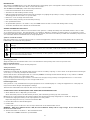
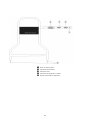
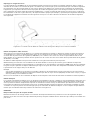
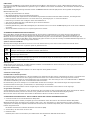
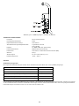
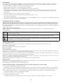
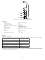
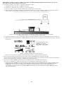
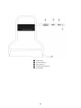
➊
On/Off Button
➋
Reference indicator
➌
Active indicator
➍
Bargraph indicator
➎
A-Frame spikes

4
A-5000
Sheath Fault Locator
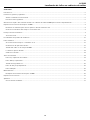
CONTENTS
Introduction ................................................................................................................................................................................................ 5
General Information and Safety .............................................................................................................................................................. 5
Symbols used in this manual ................................................................................................................................................................ 5
Safety Precautions ................................................................................................................................................................................ 5
A-5000 Sheath Fault Locator Quick Start Guide For The Experienced User ........................................................................................... 5
A-5000 Receiver Technical Specifications .................................................................................................................................................. 8
Linear A-Frames For Telecom Utilities: ................................................................................................................................................ 8
A-Frame Receiver Controls And Indicators .......................................................................................................................................... 8
Principles Of Operation ............................................................................................................................................................................. 9
Functional Theory ................................................................................................................................................................................. 9
Calibration Test Procedure ...................................................................................................................................................................... 12
Operation ................................................................................................................................................................................................. 13
Synchronize The A-Frame Receiver .................................................................................................................................................... 13
Confirm That A Fault Exists ................................................................................................................................................................ 13
Trace The Cable With The R-5000 Receiver ....................................................................................................................................... 13
Pinpoint The Fault .............................................................................................................................................................................. 13
Verify The Fault ................................................................................................................................................................................... 14
Advanced Techniques .............................................................................................................................................................................. 14
Faults Under Inaccessible Surfaces ..................................................................................................................................................... 14
Faults Under Pavement ...................................................................................................................................................................... 15
Long Distance Tracing ........................................................................................................................................................................ 15
High And Low Impedance Faults ....................................................................................................................................................... 16
Multiple Faults .................................................................................................................................................................................... 16
Maintenance ............................................................................................................................................................................................. 16
A-5000 Receiver Battery Replacement. ............................................................................................................................................. 16
Technical Specifications ........................................................................................................................................................................... 17
Appendix .................................................................................................................................................................................................. 17
APWA Marking Colors ........................................................................................................................................................................ 17

5
INTRODUCTION
The Amprobe AT-5000 Utility Locator with Sheath Fault Locating (SFL) option is designed to detect and pinpoint sheath and
other conductor faults that are in direct contact with the earth.
The AT-5000 with A-5000 (SFL) offers these unique features:
Fault level measurement at the transmitter•
Simultaneous fault finding and line tracing•
LCD bar graph representing the A-Frame signal strength for judging the proximity to faults, comparing multiple faults, and •
detecting pinholes and “trees” in a power cable
Detection of low and high resistance faults•
Automatic battery checking and low battery warning•
Non-polarized A-Frame•
Single-handed operation. No need to carry an R-5000 receiver as well as an A-frame during fault locating•
Active SFL ohmmeter and voltmeter in the Transmitter•
GENERAL INFORMATION AND SAFETY
This manual contains basic advice for the installation and operation of Amprobe Utility Line and Sheath Fault Locators as well
as accompanying accessories. The manufacturer is not liable for damage to material or humans due to non-observance of the
instructions and safety advice provided in this manual. Therefore, this manual should be provided and reviewed by all personnel
associated with the line and sheath fault locating equipment.
Symbols used in this manual
Important instructions concerning the protection of staff and equipment as well as technical safety within this document are
labeled with one of the following symbols:
Indicates a potentially hazardous situation, which, if not avoided, may result in minor or moderate injury or material
damage.
Indicates a potentially hazardous situation, which, if not avoided, could result in death or serious injury.
Notes have important information and useful tips on the operation of your equipment. Non-observance may result
in incorrect measurement results.
Operating personnel
Amprobe utility line and sheath fault locators are intended for use by utility and contractor professionals.
Repair and maintenance
Repairs and service must only be done by Amprobe.
Safety Precautions
Observed safety practices
Familiarize yourself with all required safety practices of the local utility company, or other owner of the plant before entering an
access area, or connecting an Amprobe transmitter.
Ensure that the line is de-energized and out of service, BEFORE connecting the transmitter directly to any conductor. NEVER
make a direct connection to a live power cable.
Follow the appropriate safety procedures to avoid the risk of injury if using a clamp on energized electrical or control lines.
Pay special attention when using a locator in high traffic areas.
Intended application
Safe operation is only realized when using the equipment for its intended purpose. Using the equipment for other purposes
may lead to human danger and equipment damage.
The limits described under the technical data section may not be exceeded.
A-5000 SHEATH FAULT LOCATOR QUICK START GUIDE FOR THE EXPERIENCED USER
Check Batteries Prior to Departing for the Field 1.
Check the battery level in the Transmitter, Receiver, and A-Frame by powering up each instrument.
Maximum use of the Transmitter’s SFL feature requires that the battery be fully-charged prior to field use. Amprobe
recommends charging the battery to full capacity before locating faults.
Replace/recharge if necessary. Turn the instruments OFF.
Ensure All Conductors Are De-Energized2.
Lift Grounds3.
Lift Grounds (of all conductors in the circuit) at both ends of the faulted cable section.
WARNING When the T-5000 transmitter is ON, the external OUTPUT JACK produces a high voltage. Do not touch the jack!
Electrical shock will result!
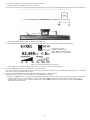
Attach Transmitter to Conductor – Check Fault Resistance4.
Make sure T-5000 transmitter is powered OFF.1.

6
Plug Black and Red conductive leads into the transmitter.2.
Stretch the Black-lead 180° away from conductor.3.
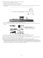
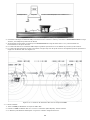
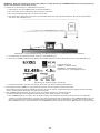
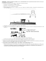
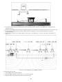
Push the ground rod into earth and clamp the Black lead to ground rod. Establish the best ground possible. See Figure 3-14.
Figure 3-1: Clamping Black Lead to Ground Rod; Clamping Red Lead to Conductor
Clamp Red lead to target conductor sheath. See Figure 3-15.
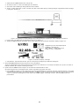
Push T-5000 transmitter SFL key. Check measured fault resistance on transmitter display. See Figure 3-2 6.
Fault Severity Guide:
0-100 KΩ – Severe Fault
100 – 500 KΩ – Medium Fault
1 MΩ and above – Light Faults
Figure 3-2: Transmitter display in SFL mode
Select frequency - 9.8 KHz or 82 KHz, pressing the f button on the Transmitter keypad.7.
Use the R-5000 Utility Line Locator Receiver to Trace the Cable5.
Press the frequency softkey (Freq) on the receiver until the frequency selected on the transmitter is displayed. Trace and mark
the cable as you proceed towards the fault.
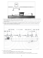
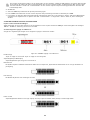
Synchronize the A-5000 A-Frame Receiver and Establish Reference Value of Fault 6.
(A-Frame receiver has a one-color band above each spike (Black or White)
Hold the A-5000 Receiver so the spike with the Black band is about two (2) steps away from the ground rod and the spike 1.
with the white band is in-line with the targeted cable. The A-5000 receiver must be placed as shown in Figure 3-3 for
synchronization and for unit to operate correctly. Push the A-5000 spikes firmly into the ground. Turn the A-5000 ON.
Wait until the arrow flashes.

7
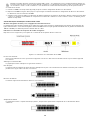
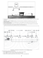
Figure 3-3: Positioning of A-5000 Receiver for Synchronization
Monitor bar-graph LCD display for arrow direction. If the arrow points AWAY from the ground rod, there is a fault.2.
If the arrow points TOWARDS the ground rod, there is no fault, and grounds and connections need to be rechecked.3.
The number of bars on the LCD indicates the potential gradient associated with the fault at the synchronization location.4.
The number of bars will decrease when you move away from the synchronization location and will increase when you get 5.
closer to the targeted fault. See Figure 3-4
Figure 3-4 : Locating the Cable Fault with A-5000 Receiver
Pinpoint the Fault7.
Keep the A-5000 parallel to the target cable.1.
Insert the A-5000 firmly in the ground every 10’ – 20’ (3 -6 m). Follow the arrow.2.
When the arrow changes direction, the fault may have been reached or passed.3.
Look at the number of bars activated as well as the “Actual” LCD reading and compare them to number of bars you
read at synchronization point as well as the “Reference” LCD reading. If the number of bars or the “Actual” and
“Reference” readings are similar to the number of bars at synchronization point, you have located the main fault.

8
Backtrack. 4.
Insert the A-5000 every 2’ (.5 m) until the arrow changes direction again. 5.
Move the A-5000 across the cable until a slight movement causes the arrow to change direction. The fault is located at the 6.
center of the A-5000.
Check entire cable for multiple faults. If more faults are present, check the “Active” LCD number at each fault site and 7.
compare it to the “Reference” number. The higher the “Active” number the larger the fault.
A-5000 RECEIVER TECHNICAL SPECIFICATIONS
Linear A-Frames For Telecom Utilities:
Telecom faults, however, are typically higher resistance faults than power. The Linear A-frame A-5000 provides greater sensitivity
in the fault range of 100 KΩ – 10 MΩ to detect multiple faults in a cable.
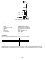
A-Frame Receiver Controls And Indicators
See Figure 4-1 for the location of the Receiver controls described below:
Figure 4-1: A-5000 Controls and Indicators
On/Off Button:
Push and release to turn ON. Push and release to turn OFF.
LCD Bar Graph Display:
The bar graph indicates three types of information:
Battery Status:
The solid bars indicate the battery level. If only one bar appears, replace the battery. The battery status is displayed for three
(3) seconds at Power ON.
Direction of Fault:
The flashing arrows will display the direction to the fault
Magnitude of Fault
The bar graph consists of twelve (12) bars with each bar representing the magnitude of the fault(s) as described below.

9
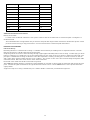
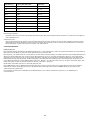
Impedance (Ω) Linear Active/Reference Bars
450 828 12
1K 694 11-12
5K 413 11
10K 302 10-11
20K 222 10
30K 182 10
50K 139 9-10
100K 90 8-9
327K 45 7-8
1M 21 6-7
Additional A-Frame Receiver Features
Battery Access Plate
Located on the underside of Receiver control panel. Remove the two thumbscrews to release the plate. See Figure 9-1.
Conductive Pads
The A-Frame Receiver is shipped with two protective foam pads with large washers attached to the Receiver probes. These
pads are used for tracing on dry, hard surfaces. Protect and save these conductive pads and washers.
PRINCIPLES OF OPERATION
Functional Theory
Reviewing the basics of sheath fault locating is a valuable exercise before proceeding even for experienced users. This will
improve the chances of finding the fault and saving time.
Comparing electrical current to water flowing through a pipe applies extremely well to fault locating. Just like trying to find a
leak in a water pipe, you might seal off one end, pump water into the other, and look for water to appear near the leak. The
principles of sheath fault locating are identical. The cable equivalent of sealing off the pipe is to lift all connections at both
ends of the cable, creating a high resistance open condition. The “water” in this case is the current flowing through the cable
towards the fault. We look for the current “leak” with an A-Frame.
Both ends of the cable must be disconnected from ground.
The T-5000 transmitter applies a low frequency signal between an isolated conductor with an earth fault and another ground
point. This 4.8 Hz signal is induced into the ground from the fault location. The A-5000 Receiver contact probes detect this
signal pattern.
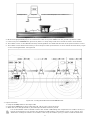
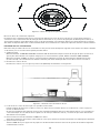
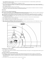
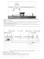
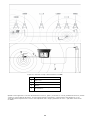
A typical hookup for locating a sheath fault, also called a shield-to-earth fault, is illustrated in Figure 5-1.

10
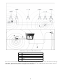
Figure 5-1: Typical T-5000 Transmitter Connection
1 Black Lead
2 Red Lead
3 Ground Rod
4 Fault
5 Faulty conductor open on both ends
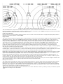
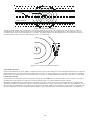
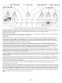
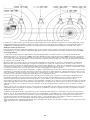
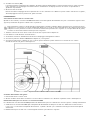
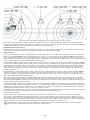
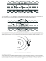
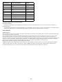
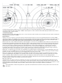
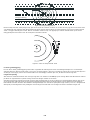
As current flows from the transmitter and through the fault, an earth voltage gradient field is created. Its center is at the
fault. This gradient field has a pattern as depicted in Figure 5-2, like pond water ripples when you throw a rock in it or
the rings of a tree stump.)

11
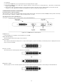
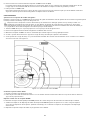
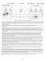
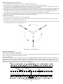
Figure 5-2: Signal Pattern Around Fault and Ground Point
The A-Frame Receiver compares the readings taken by the two probes and determines the direction and size of the fault.
Directional blinking arrows guide the operator to the exact source of the fault. The A-5000 bar graph and numerical active LCD
display indicates the relative distance to the fault and it is size.
Earth Voltage Gradient
Note in Figure 5-2 that the gradient pattern appears to be concentric circles near the fault. Properly interpreting this pattern is
the key to successful operation of the A-5000.
Equipotentials
The circles shown in Figure 5-2 represent lines of equal voltage. The boxes show what the bar graph will display with the A-5000
in different positions. Thus, if the A-5000 A-Frame were inserted so that both of the ground spikes were on the same circle,
there would be no difference in voltage between them. The bar graph will show zero, the arrows will become erratic and the
numerical active display will show a zero. One of these positions occurs when the fault is directly between the spikes.
This result can also occur midway between the ground spike and a fault and when the A-5000 is exactly perpendicular to the
fault. There is a return field around the transmitter ground spike. As you move toward the fault, the bars and the active
numerical number will decrease until you reach the midpoint between the fault and ground spikes. At the half waypoint
between the fault and ground spike, the signal strength is at it is absolute lowest. At this point the bar graph and active display
will show zero and the arrows become erratic.
To determine if you are midway between faults or directly over a fault, move the A-5000 further from the transmitter and
measure again. If the arrows tell you to continue in this direction, the zero point was a midpoint. If the arrows tell you to return
toward the transmitter, the zero point was a fault. As you continue, they will increase until you reach the fault.
Nearly 70% of the signal exists within the last 1/3 of the distance between the ground spike and the fault. The amount of signal
measured and displayed by the A-5000 is proportional to the number of field lines in Figure 5-2 between the A-5000 A-Frame
spikes. Thus, the maximum signal point occurs when one A-Frame spike is directly above the fault.
By probing around the ground point, a user can learn what to expect at the fault from the A-Frame bar graph response. As
shown in Figure 5-2, the signal pattern around the fault and ground point is identical (if there are no nearby conductors). This
means that the A-Frame will react the same way around the fault as at the ground point.
As you move toward the fault, the bars and the active numerical display will decrease until you reach the midpoint between the
fault and ground spike. As you continue, they will increase until you reach the fault.
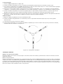
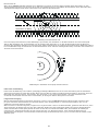
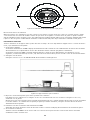
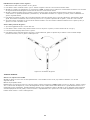
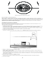
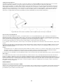
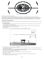
Multiple Fault Patterns
The signal pattern created by two faults in a line is depicted in Figure 5-3. The two faults are shown without the ground point.
Notice that from a distance the two faults will have the appearance of a single fault due to the equipotential circle around
them both. As you get closer, the individual faults become apparent. There is an area between two faults where the A-Frame
may give a false indication of another fault. This is caused by the two faults canceling each other. Errors can be avoided in this
situation by following the procedure described in Section 7.7.
We recommend that multiple faults be attacked one at a time. Whenever a fault is positively located, it should be repaired
before looking for the other faults.

12
F1
F2
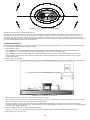
Figure 5-3: Multiple Fault Signal Patterns
Distortion Due to Adjacent Conductors
Whenever a non-insulated adjacent conductor lies between a fault and the ground return point, the return current tends to
concentrate on the conductor instead of flowing through the earth. This situation can shrink the signal pattern near the fault,
which would tend to reduce the detectable signal away from the fault. Possible distortion problems such as the described
situation can be avoided by first tracing the faulty conductor and looking for adjacent conductors prior to fault locating.
CALIBRATION TEST PROCEDURE
Perform this instrument test procedure on a lawn prior to field site use. If grass or dirt is not available, indoor carpeting may be
used.
Check the Batteries1.
Turn the T-5000 transmitter ON. The transmitter LCD will display the battery capacity level. Ensure the transmitter battery is
fully charged for optimal operation. Turn the transmitter OFF.
Turn the A-5000 Receiver ON. The solid bars indicate the battery level. If only one bar appears, replace the battery (1 each,
9V). The battery status is ON for 3 seconds at turn on.
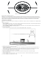
Connect the Test Cables2.
Connect the Black and red connection leads to the transmitter OUTPUT JACK. See Figure 6-1.
Figure 6-1: Checkout Test Set-Up
Spread the Test Leads as Far Apart as Possible3.
Insert the ground spike and attach the Black cable. Insert a screwdriver into the ground and connect the Red cable to it,
creating a simulated fault.
This test can also be done by pushing the metal end of the clamps directly into the ground so that they make electrical
contact. When using a carpet in this checkout procedure connect test cable clamps directly to the carpet.
Push the SFL T-5000 transmitter button on the keypad4.
Wait for the SFL high-voltage output to be generated and observe the fault resistance transmitter display.
Synchronize the Receiver5.
Hold the A-5000 so that the black spike is closer to the ground connection. Push the A-Frame firmly into the ground.
Push the A-5000 Receiver On/Off Switch to ON6.

13
The A-Frame Receiver will repeat its battery test. After the battery test, the arrow facing the simulated fault (Red test clamp)
flashes and a potential gradient number is shown on the Active and Reference LCD display.
Rotate the A-5000 180°7.
Note that the arrow now facing the red test clamp flashes. As the A-Frame is moved around the fault the arrow closest to the
simulated fault should flash.
OPERATION
Synchronize The A-Frame Receiver
By synchronizing, the A-5000 memorizes the phase of the transmitter signal. This allows it to recognize the reverse phase signal
coming from the fault and direct you to it.
Resynchronize the Receiver every 45 minutes to maintain optimum calibration. You may do this near the ground rod or
near a fault. At the ground rod, the black A-Frame spike must be nearer to the ground rod with the white spike facing
toward the fault. At a fault, the white A-Frame spike must be nearer to the fault.
Hold the A-5000 so that the black spike is closest to the ground rod.1.
Push the A-Frame spikes into the ground.2.
Switch the A-5000 Receiver ON. Wait until the arrow flashes on the bar graph.3.
If the arrow points away from the ground spike, there is a fault.4.
If the arrow points towards the ground spike, there is no fault. Recheck the grounds and connections if a fault is wrongly 5.
given. See Figure 7-1.
Figure 7-1: Synchronizing the A-5000
Confirm That A Fault Exists
Remove the A-Frame from the ground.1.
Rotate it 180° and re-insert it into the ground. The arrows should reverse directions and point away from the ground spike.2.
Trace The Cable With The R-5000 Receiver
The AT-5000 Utility Line Locator allows you to trace the line and search for the fault at the same time.
Check the R-5000 Receiver for cable tracing frequency. Aim the Receiver at the Red lead and cycle through the Receiver 1.
frequencies – 9.8 KHz or 82 KHz, to confirm that the selected tracing frequency is being received.
Trace and mark the cable as you proceed towards the fault.2.
Pinpoint The Fault
Keep the A-5000 parallel to the target cable1.
Insert the A-Frame every 10’ – 20’ (3 - 6 m). Follow the arrow and monitor the active number.2.
When locating with the A-5000, make sure that the probes are inserted well into the ground. A good physical ground 3.
connection is needed to receive strong signal.

14
When the arrow changes direction, back track. Check the “Active” LCD number and compare it to the “Reference” LCD 4.
number. If both active and reference numbers have the same or similar value, you have found the major fault.
Insert the A-Frame every 2’ (50 cm) until the arrow changes direction again, then turn it 90 degrees. Check for obvious causes 5.
where a fault is suspected, such as recent excavation.
Continue to move the A-Frame across the cable until a slight movement causes the arrow to change directions. When this 6.
happens, the fault is located at the center of the A-Frame.
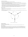
Verify The Fault
Move slightly off to one side of the cable.1.
Insert the A-Frame into the ground at various positions around the suspected fault site (like the hands of a clock).2.
The arrow should always point toward the fault.3.
Place the other spike in the ground at the fault site and repeat the process. The arrow should always point inward, toward 4.
the fault. See Figure 7-2.
Figure 7-2: Fault Confirmation
ADVANCED TECHNIQUES
Faults Under Inaccessible Surfaces
When the faults exist beneath a paved or other inaccessible area, the fault may be located using one of the following methods.
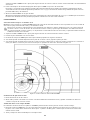
Perpendicular Method
Carefully trace the location of the faulty conductor. Hold the A-5000 parallel to the cable path. As you move away from the
ground rod the bar graph and the active number will gradually decrease until reaching the midpoint. It will then increase until
reaching the fault. When the A-Frame center passes a line perpendicular to the Sheath fault, the directional arrow indicators
will rapidly change positions and the bar graph and active number will drop to zero. See Figure 8-1.
Paved Surface
Ca ble Fault
Figure 8-1: Perpendicular Method
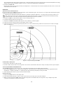
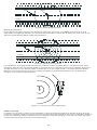
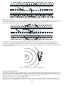
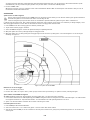
Triangulation Method
As shown in Figure 8-2, (the point where the signal strength is a minimum) if the A-5000 is positioned exactly on an
equipotential circle, a perpendicular line from the center of the A-Frame will pass through the fault. The intersection of any two
such perpendicular lines defines the fault location.

15
Paved Surface
Ca ble Fault
Figure 8-2: Triangulation Method
To find an equipotential circle (see Figure 8-3) insert the A-Frame into the ground and pivot around one spike. Rotate the
A-Frame back and forth until the exact point is found where the flashing arrows change direction. The A-Frame is now on
an equipotential circle and is perpendicular to the fault. By marking this line and repeating the process with the A-Frame at
another nearby location, the two lines will intersect or cross at the fault.
Figure 8-3: Locating an Equipotential Circle
Faults Under Pavement
Faults under pavement or other slightly conductive surfaces can be found using the foam pads supplied with the unit. Saturate
the pads with water and insert the A-Frame spikes into the pads. Locate the fault as you normally would. Be sure to keep the
pads as moist as possible, but do not let the water form a continuous puddle between the pads as this will short out the signal.
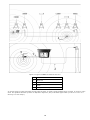
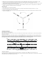
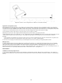
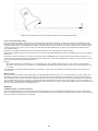
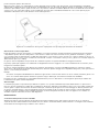
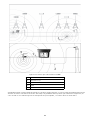
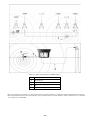
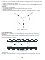
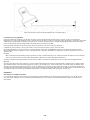
Long Distance Tracing
As the distance to the fault increases, the signal picked up by the A-5000 is proportionally reduced. This condition can lead to
problems if the signal levels are reduced to the point that they can no longer be detected by the A-Frame.
Whenever working with weak signals due to long distance faults (or other reasons), increased sensitivity can be obtained by
extending the distance between the A-Frame spikes using the extension cable. This extension method can be applied to any of
the previously discussed methods including the conductive foam pads. When working with very long distances, as in fiber optic
runs, the sensitivity can be increased even further using a longer insulated wire to extend the A-Frame span. See Figure 8-4.

16
Figure 8-4: Fault Location Using Extension Cable for Increased Sensitivity
High And Low Impedance Faults
Before beginning a fault search it is a good idea to know the severity of the fault. This is measured in terms of its resistance
or impedance to ground. Faults where the ground is wet and/or a very large piece of the insulation is missing are found at the
low end of the range (<500 Ohms). Conditions where the ground is very dry and/or the actual fault is a small pinhole where the
conductor has a very small ground contact area are found at the high end of the fault range (>1-3 MΩ).
A low impedance fault is the easiest to find since there is more signal to detect.
Generally, the more bars and a higher number displayed at synchronization, the larger the fault.
A high impedance fault is more difficult to locate. Characteristically, the A-5000 Receiver may not detect the signal after moving
a short distance away from the ground point. The higher the impedance of the fault, the closer you must be to detect it.
Example
If the A-Frame only reliably points away from the ground connection within 20’ (3 m), then the A-frame will only detect the
fault within about 20’ (3 m). Outside this distance the signal is too weak to reliably detect.
For this reason we highly recommend tracing and marking the line before searching out high impedance faults.
Multiple Faults
Locating multiple faults is the most difficult and confusing fault situation. It is especially important in this case to accurately
trace the faulty conductor before beginning the fault search. Stay exactly above the line if possible and verify each suspected
fault by monitoring the active number to see which fault has the higher number. Remember that a very strong or low
impedance fault will mask the detection of a weak or high impedance fault. The safest and best way to find multiple faults is to
repair each fault as it is positively identified and then continue the search. See Figure 5-3.
MAINTENANCE
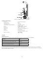
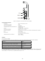
A-5000 Receiver Battery Replacement.
Loosen the two thumbscrews located on the underside of the Receiver housing. Gently pull out battery door. Be careful not
to pull on the battery wires. Remove battery from battery holder and disconnect battery. Reverse procedure for installing new
battery.

17
C onne c tor
Figure 9-1: A-5000 Receiver Battery Replacement
TECHNICAL SPECIFICATIONS
Frequency: 4.8 Hz Crystal Controlled
Input Sensitivity: 5 MV
Sensitivity Control: Automatic
Active/Reference Signal Sensitivity Logarithmic: 0 − 120
Linear: 0 − 999
Battery: 9 V NEDA 1604 or equivalent
Battery Life: 100 hr. continuous use
Battery Test: Automatic at power ON for 3 sec.
Weight: 4.4 lb (2.0 kg)
Dimensions: 32” H x 22” W x 1” D
(81 cm H x 56 cm W x 2.5 cm D)
Operational Temp: -4°F − +120°F
(-20°C − +50°C)
APPENDIX
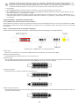
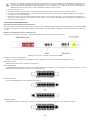
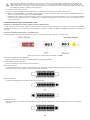
APWA Marking Colors
The following color markings have been established by the American Public Works Association (APWA):
Conductor Color
Electric power lines, cables, or conduits Red
Communication lines, cables, Conduits, CATV Orange
Gas, oil, petroleum, or other gaseous materials Yellow
Sewers, storm and sanitary, drain lines Green
Water, irrigation, or slurry lines Blue
If you have any questions regarding marking requirements or procedures in the United States, please call your local One Call
Center. International customers: please check with your local regulatory authorities or utility companies required color markings
may vary between different countries.

18
La page est en cours de chargement...
La page est en cours de chargement...
La page est en cours de chargement...
La page est en cours de chargement...
La page est en cours de chargement...
La page est en cours de chargement...
La page est en cours de chargement...
La page est en cours de chargement...
La page est en cours de chargement...
La page est en cours de chargement...
La page est en cours de chargement...
La page est en cours de chargement...
La page est en cours de chargement...
La page est en cours de chargement...
La page est en cours de chargement...
La page est en cours de chargement...
La page est en cours de chargement...
La page est en cours de chargement...
La page est en cours de chargement...
La page est en cours de chargement...
La page est en cours de chargement...
La page est en cours de chargement...
La page est en cours de chargement...
La page est en cours de chargement...
La page est en cours de chargement...
La page est en cours de chargement...
La page est en cours de chargement...
La page est en cours de chargement...
La page est en cours de chargement...
La page est en cours de chargement...
La page est en cours de chargement...
La page est en cours de chargement...
La page est en cours de chargement...
La page est en cours de chargement...
La page est en cours de chargement...
La page est en cours de chargement...
La page est en cours de chargement...
La page est en cours de chargement...
La page est en cours de chargement...
La page est en cours de chargement...
La page est en cours de chargement...
La page est en cours de chargement...
La page est en cours de chargement...
La page est en cours de chargement...
La page est en cours de chargement...
La page est en cours de chargement...
La page est en cours de chargement...
La page est en cours de chargement...
La page est en cours de chargement...
La page est en cours de chargement...
La page est en cours de chargement...
La page est en cours de chargement...
La page est en cours de chargement...
La page est en cours de chargement...
La page est en cours de chargement...
La page est en cours de chargement...
La page est en cours de chargement...
La page est en cours de chargement...
La page est en cours de chargement...
La page est en cours de chargement...
La page est en cours de chargement...
La page est en cours de chargement...
La page est en cours de chargement...
La page est en cours de chargement...
La page est en cours de chargement...
La page est en cours de chargement...
La page est en cours de chargement...
La page est en cours de chargement...
La page est en cours de chargement...
La page est en cours de chargement...
La page est en cours de chargement...
La page est en cours de chargement...
La page est en cours de chargement...
La page est en cours de chargement...
La page est en cours de chargement...
La page est en cours de chargement...
La page est en cours de chargement...
La page est en cours de chargement...
La page est en cours de chargement...
La page est en cours de chargement...
La page est en cours de chargement...
La page est en cours de chargement...
La page est en cours de chargement...
La page est en cours de chargement...
La page est en cours de chargement...
La page est en cours de chargement...
La page est en cours de chargement...
La page est en cours de chargement...
La page est en cours de chargement...
La page est en cours de chargement...
-
 1
1
-
 2
2
-
 3
3
-
 4
4
-
 5
5
-
 6
6
-
 7
7
-
 8
8
-
 9
9
-
 10
10
-
 11
11
-
 12
12
-
 13
13
-
 14
14
-
 15
15
-
 16
16
-
 17
17
-
 18
18
-
 19
19
-
 20
20
-
 21
21
-
 22
22
-
 23
23
-
 24
24
-
 25
25
-
 26
26
-
 27
27
-
 28
28
-
 29
29
-
 30
30
-
 31
31
-
 32
32
-
 33
33
-
 34
34
-
 35
35
-
 36
36
-
 37
37
-
 38
38
-
 39
39
-
 40
40
-
 41
41
-
 42
42
-
 43
43
-
 44
44
-
 45
45
-
 46
46
-
 47
47
-
 48
48
-
 49
49
-
 50
50
-
 51
51
-
 52
52
-
 53
53
-
 54
54
-
 55
55
-
 56
56
-
 57
57
-
 58
58
-
 59
59
-
 60
60
-
 61
61
-
 62
62
-
 63
63
-
 64
64
-
 65
65
-
 66
66
-
 67
67
-
 68
68
-
 69
69
-
 70
70
-
 71
71
-
 72
72
-
 73
73
-
 74
74
-
 75
75
-
 76
76
-
 77
77
-
 78
78
-
 79
79
-
 80
80
-
 81
81
-
 82
82
-
 83
83
-
 84
84
-
 85
85
-
 86
86
-
 87
87
-
 88
88
-
 89
89
-
 90
90
-
 91
91
-
 92
92
-
 93
93
-
 94
94
-
 95
95
-
 96
96
-
 97
97
-
 98
98
-
 99
99
-
 100
100
-
 101
101
-
 102
102
-
 103
103
-
 104
104
-
 105
105
-
 106
106
-
 107
107
-
 108
108
-
 109
109
-
 110
110


Amprobe A-5000 Sheath Fault Locator Manuel utilisateur
- Taper
- Manuel utilisateur
dans d''autres langues
Documents connexes
-
Amprobe ECB50A, ECB50A-E & ECB50A-FGIS Circuit Breaker Finder Cable Tracers Manuel utilisateur
-
-
-
Amprobe UAT-610 & UAT-620 Manuel utilisateur
-
Amprobe Kit localizador de cables avanzado AT-8030 de Amprobe Manuel utilisateur
-
Amprobe AT-6000 Manuel utilisateur
-
Ampro AT-6010-R Manuel utilisateur
-
-
-
Autres documents
-
Megger DET2/2 Manuel utilisateur
-
SEFRAM MW9520 Manuel utilisateur
-
VOLTCRAFT LSG-10 SE Cable Detector Manuel utilisateur
-
Greenlee PE2003 Ground Fault Locator Manuel utilisateur
-
SPX SuperCAT 4S Manuel utilisateur
-
VOLTCRAFT LSG-10 Operating Instructions Manual
-
COLLINGWOOD SL240 Manuel utilisateur
-
Wohler L 200 Mode d'emploi