Harman Stove Company Advance Installation & Operating Manual
- Catégorie
- Poêles
- Taper
- Installation & Operating Manual

SAFETY NOTICE
PLEASE READ THIS ENTIRE MANUAL BEFORE YOU INSTALL AND USE YOUR NEW ROOM HEATER. FAILURE
TO FOLLOW INSTRUCTIONS MAY RESULT IN PROPERTY DAMAGE, BODILY INJURY, OR EVEN DEATH.
FOR USE IN THE U.S. AND CANADA. SUITABLE FOR INSTALLATION IN MOBILE HOMES
IF THIS HARMAN STOVE IS NOT PROPERLY
INSTALLED, A HOUSE FIRE MAY RESULT. FOR YOUR SAFETY, FOL-
LOW INSTALLATION DIRECTIONS.
CONTACT LOCAL BUILDING OR FIRE OFFICIALS ABOUT RESTRICTIONS AND INSTALLATION INSPECTION
REQUIREMENTS IN YOUR AREA.
CONTACT YOUR LOCAL AUTHORITY (SUCH AS MUNICIPAL BUILDING DEPARTMENT, FIRE DEPARTMENT, FIRE
PREVENTION BUREAU, ETC.) TO DETERMINE THE NEED FOR A PERMIT.
CETTE GUIDE D'UTILISATION EST DISPONIBLE EN FRANCAIS. CHEZ VOTRE CONCESSIONNAIRE DE HARMAN
STOVE COMPANY.
SAVE THESE INSTRUCTIONS.
The Harman Advance Pellet Stove
Installation & Operating Manual
R12
“Ce manuel est disponible en Français sur demande”

2
Automatic Operation 3
Manual Operation 5
ESP Control 7
Assembly & Installation 8
Venting 12
Maintenance 19
Trouble-Shooting 26
Specications 27
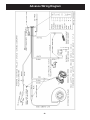
Wiring Diagram 28
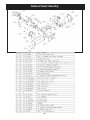
Feeder Parts 29
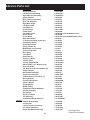
Parts List 30
Warranty 31
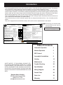
Introduction
Harman Home Heating
352 Mountain House Road
Halifax, PA 17032
Table of Contents
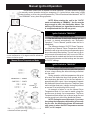
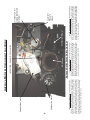
The Advance Pellet Heater
This heating appliance does not just have automatic ignition, it has total automatic temperature control. The Advance
uses a small room sensor rather than a wall thermostat for a more accurate temperature control.
The Advance's control panel is designed for easy and efcient operation. It has 2 automatic modes of operation and 2
manual modes of operation. The Advance's specially designed burn pot and the "Advance Igniter" Automatic Ignition
System, allow the unit to burn a large variety of biomass fuels with varying ash content. The Advance feed system
has a maximum feed rate of 6 lbs. per hour and a minumum (maintenance) feed rate of 1.0 lbs. per hour.
This 0 to 48,000 BTU pellet stove has an accordian style heat exchanger system that allows maximum surface area
for the most efcient heat transfer in a smaller rebox.
The unit has an easy to clean combustion system with an ash pan that holds ash from 1 ton of burned premium
pellets.
This unit is equipped with several different safety devices which will be explained later in this manual.
SAFETY NOTICE: IF THIS HARMAN ADVANCE PEL-
LET STOVE IS NOT PROPERLY INSTALLED. A HOUSE
FIRE MAY RESULT. FOR YOUR SAFETY, FOLLOW THE
INSTALLATION DIRECTIONS. CONTACT LOCAL BUILD-
ING OR FIRE OFFICIALS ABOUT RESTRICTIONS AND
INSTALLATION INSPECTION REQUIREMENTS IN YOUR
AREA.
Please copy
your serial
number
from the label on your stove to
the box below.
SERIAL NUMBER
Model: ADVANCE
Room Heater Pellet Fuel Burning
Also for use in Mobile Homes.
This pellet burning applicance has been tested and listed for use in Manufactured Homes in
accordance with OAR 814-23-900 through 814-23-909
Serial No./N
o
de série
Modèle : ADVANCE
Appareil de chauffage à granulés de bois
Manufactured by/Fabriqué par :Harman Stove Company
352 Mountain House Road, Halifax, PA 17032 (É.-U.)
2007
2008 2009
APR
MARFEB
MAY
JAN
JUN JUL
AUG
SEPT
OCT
NOV
DEC
Date of Manufacture/Date de fabrication :
OMNI-Test Laboratories, Inc.
Report #/Rapport #135-S-10-2
Test to/Testé à ASTM E 1509-04, and ULC-C1482-M91
Tested by Emitech, Apave & BFP Electronique
EN60335-1, EN55014-1, EN 61000-3-2, EN 14785:2005
Test date: February 2004
Room Heater Pellet Fuel Burning type (UM) 84-HUD
Do not remove this label/Ne pas enlever cette étiquette.Made in USA/Fabriqué aux É.-U.
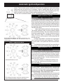
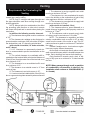
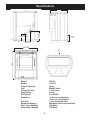
MINIMUM CLEARANCES TO
COMBUSTIBLES
Back Wall to Appliance 1”
Side Wall to Appliance 10”
Ceiling to Appliance 24"
Corner Installation
Walls to Appliance 7”
Use a non-combustible floor protec-
tor extending under unit and to the
sides, front and b
ack of unit as shown
in Floor Protec
tion Diagram. Measure
front distance from the surface of the
glass door.
Recommended: Non-combustiblle
floor protection extending beneath
the fluepipe when installed with hori-
zontal venting or under the top vent
adapter with vertical installation.
FLOOR PROTECTION
Sides 2”/5 cm
Back 0”/0 cm
Front 6”/15 cm
Tests réalisés par OMNI TEST LABORATORIES, Inc.
Rapport N
o
135-S-10-2
Essais selon les normes 1509-04 de l’ASTM et C 1482-M91ULC
Appareil de chauffage à granulés (UM) 84-HUD
NORMES EUROPEENNES:
NF EN 14785 CETIAT – Déc. 2006
AEMC MESURES EN50366 - Déc. 2006
EMITECH, APAVE & BFP Electronique - Fév. 2004
EN55014-1, EN 55014-2, EN 61000-3-2, EN 61000-3-3
PREVENTION DES INCENDIES
Respecter scrupuleusement les instructions du constructeur pour l’installation
et les consignes de fonctionnement. Respecter les règles de sécurité en
vigueur dans votre région.
AVERTISSEMENT POUR MOBILE HOMES : Ne pas installer dans une chambre.
Il est impératif de prévoir une prise d’air extérieur. L’intégrité structurale du
plancher, du plafond et des murs doit être strictement préservée.
Se reporter aux instructions du fabricant et aux réglementations spécifiques
locales concernant les précautions requises lors de la traversée d’un mur ou
d’un plafond. Contrôler et nettoyer fréquemment tout le système d’évacuation
des fumées conformément aux recommandations du constructeur.
Utiliser des conduits « Spécial granulés » de diamètre 80 mm ou 100 mm.
Ne pas raccorder ce poêle à un conduit de cheminée déjà utilisé pour un
autre appareil de chauffage.
FONCTIONNE EXCLUSIVEMENT AVEC DES GRANULES DE BOIS.
SE CONFORMER AUX INSTRUCTIONS D’UTILISATION
Consommation maximale: 2,16 kg/h
Caractéristiques électriques: 230/250 VC, 50 Hz, Intensité au démarrage 3
A, Intensité fonctionnement normal 1,1 A
Tenir le cordon d’alimentation à l’écart du poêle.
DANGER : Risque d’électrocution. Débrancher l’appareil avant toute
intervention.
Ne remplacer la vitre qu’avec une vitre céramique de 5 mm de même qualité
disponible auprès de votre revendeur.
Pour une information plus complète, se reporter à la notice d’utilisation.
Tenir la porte frontale et le couvercle de trémie hermétiquement clos durant le
fonctionnement de l’appareil.
Puissance calorifique émise: Nominale: 10,5 Kw Réduite: 1,8 Kw
Concentration CO (à 13 % O2)
à puissance nominale : <0,02 % à puissance réduite : <0,04 %
Rendement: à puissance nominale : 84% à puissance réduite : 73 %
DISTANCES DE SECURITE PAR RAPPORT AUX MATERIAUX COMBUSTIBLES
Entre mur arrière et appareil 2.5 cm
Entre paroi latérale et appareil 25.5 cm
Plafond - Dessus poele 61 cm
Installation en angle
Entre murs et appareil 18 cm
Utiliser une protection de sol non combustible sous l’appareil qui s’étend sur
les côtés, l’avant et l’arrière du poêle (voir schéma). Pour la distance à l’avant,
mesurer à partir de la surface de la porte en verre.
Il est recommandé que la protection s’étende jusque sous le conduit en cas
d’installation d’un conduit horizontal ou sous le té en cas de conduit vertical.
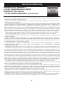
AGENCE AMÉRICAINE POUR LA PROTECTION DE L’ENVIRONNEMENT
Ce modéle est dispensé par EPA certification d’après 40 CFR 60.531 par dèfinition [Appareil à bois(A) Ratio air/combusiton]
U.S. ENVIRONMENTAL PROTECTION AGENCY
This model is exempt from EPA certification under 40 CFR
60.531 by definition [Wood Heater (A) “Air-to-Fuel Ratio”].
PROTECTION DU PLANCHER
Côtés 5 cm
Arrière 0 cm
Avant 15 cm
“PREVENT HOUSE FIRES” Install and use only in accordance with
manufacturer’s installation and operation instructions. Contact local build-
ing or fire officials about restrictions and inspection in your area.
WARNING: FOR MANUFACTURED HOMES: Do not install appliance
in a sleeping room. An outside combustion air inlet must be provided.
The structural integrity of the manufactured home floor, ceiling and walls
must be maintained.
Refer to manufacturer’s instructions and local codes for precautions
required for passing chimney through a combustible wall or ceiling.
Inspect and clean exhaust venting system frequently in accordance with
manufacturer’s instructions.
Use a 3” or 4” diameter type “L” or “PL” venting system.
Do not connect this unit to a chimney flue servicing another appliance.
FOR USE WITH PELLETIZED WOOD FUEL ONLY.
Input Rating Max: 5.7 lb. fuel/hr.
Electrical Rating: 240 VAC, 50 Hz, Start 2.0 AMPS, Run 1.1 AMPS
U.S. Electrical Rating: 115 VAC, 60 Hz, Start 4.1 AMPS, Run 2.2 AMPS
Emission of CO in Combustion:
Nominal Heat Output: <.02%, Reduced Heat Output: <.04%
Flue Gas Temperature: 224 C
Thermal Output: 10.5kW
Energy Efficiency: Nominal: 84%, Reduced: 73%
Fuel Type: Wood Pellets, 5mm diameter, 20mm long
Route power cord away from unit.
DANGER: Rish of electrical shock. Disconnect power supply before servicing.
Replace glass only with 5mm ceramic available from your dealer.
For further instruction refer to owner’s manual.
Keep viewing and ash removal doors tightly closed during operation.
INSTALL WITH MINIMUM
CLEARANCES TO WALLS AS SHOWN
TAILLE MINIMALE
DE LA PROTECTION DE SOL.
FLOOR PROTECTOR MINIMUM SIZE
7”/18cm
6”/15cm
1”/2.5cm
6”/15cm
6”/15cm
10”
25.5cm
1”/2.5cm
7”
18cm
TESTED TO: UL 1482
ASTM E1509
OREGON 814-23-900
ULC-S627, WH-PN 025
European Standards
Tested by EMITECH, APAVE and BFP Electronique
EN 550 14-1, EN 550 14-2, CEI 335-1
TEST DATE: MARCH 2000
TEST DATE: JUNE 1999
Taille minimale de la protection de sol.

3
The Advance pellet stove is more than just automatic ignition, it is also automatic temperature
control. The automatic system will allow the re size to be adjusted to match the heating
needs and even put the re out if necessary. If heat is needed after the re is out, the
Advance will automatically re-ignite and adjust the re size to match the heating need. The
totally automatic room sensor mode is recommended because of its efciency.
The unit can be switched between "AUTO" and "MANUAL" at any time during operation.
Automatic Ignition/Operation
Room Temperature Mode: This setting will produce a room
temperature of 70 degrees with the distribution blower at
medium speed.
This setting will produce medium heat with the
distribution blower on "low".
This setting will produce continuous maximum heat
output with the distribution blower at full speed.
Stove Temperature Mode
Igniter switch to "AUTO"
Room Temperature Mode
In "Room Temp Mode" heat output is controlled
automatically by the Room Sensing Probe. When the
Room Sensing Probe calls for heat, the stove will increase
output. When the Room Sensing Probe is getting close to
the set temperature, the stove will begin to level off output
and keep the re burning at just the right temperature to
maintain that setting.
High output is determined by the feed rate setting.
This setting, generally on #4, can be increased if higher
burn rates are necessary. The unit's maximum burn rate
should not create less than 1" of ash on the burn pot front
edge. See Fig.2, Page 4. Overfeeding is not a safety
concern, but fuel may be wasted if unburned pellets fall
into the ash pan.
In "Room Temp Mode" a constant fuel consumption
rate is sacriced for exact room temperature. Therefore,
as it gets colder more pellets will be burned automati-
cally.
The distribution blower speed will vary according to
the position of the mode selector pointer, and re size.
Igniter switch to "AUTO"
Stove Temperature Mode
This allows for automatic ignition upon start-up only.
The unit can then be set at any desired setting. The heat
output and fuel consumption will remain constant regard-
less of room temperature. The unit's maximum feed rate
should not create less than 1" of ash on the burn pot front
edge. See Fig 2, Page 4.
The unit's low burn or maintenance setting is as
low as it will go. It will not go out unless it runs out of
fuel or is turned off.
Shut-Down Procedure
To kill the re or stop burning the stove, turn the Mode
Selector to "OFF". This will cause the re to diminish and
burn out. When the re burns out and the stove cools down
everything will stop. Note: The combustion blower will run
forapproximately1houraftertherecools.
If you pull the plug to shut down the stove, all motors will
stop. This may cause incomplete combustion and smoke in the
rebox. If the load door is opened the smoke may escape.
The best way to shut down the stove is simply let it run
out of pellets, then the stove will shut down automatically.

4
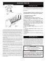
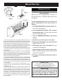
Starting First Fire
Igniter Switch to"AUTO"(up position)
Make sure the unit is plugged into a 120 VAC,
60 HZ electrical source. The power light should be the
only light lit.
To avoid unwanted smoke, be sure there is no fuel
or combustibles in the ash pan prior to lighting.
1. Turn Mode Selector to "OFF".
2. Fill hopper with pellets.
1
3. Clean burn pot with scraper, if necessary.
5
4. If starting after an empty hopper, turn Feed
Adjuster to "TEST" (for one 60 second cycle).
2
This
will purge pellets into the auger tube and also allow you
to check the motors for operation. NOTE: The auger
motor will not operate with the view door or ash
pan door open.
3
5. Turn Feed Adjuster to #4.
4
6. Flip the Igniter Switch up into the "AUTO"
position.
7. Turn the Temperature Dial to desired room
temperature.
8. Turn Mode Selector to Room Temperature or Stove
Temperature.
9. Fill hopper with pellets and remove ashes as
required.
6
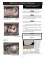
Automatic Start Up
1. Fines are small pieces of broken pellets (sawdust). Fines do not
ow easily and often build up on the hopper funnel bottom angles.
These nes can be pushed into the feeder opening and then ll the
hopper with pellets. As the system works, they will be burned.
2. The "TEST" cycle will operate the feeder motor for exactly one
minute. Turning to "TEST" again and again may purge too much
fuel into the burn pot causing excessive smoke on start-up.
3. The rebox low pressure switch will not allow the auger motor
or the igniter element to operate if the view door or the ash pan
door are open.
4. Adjust Feed Rate. If this is your rst re or you are trying different
pellets, set the feed adjuster to #4, Fig. 1. This is a conservative
number and will probably need to be increased. After you know a
feed rate setting that works well, use that setting. Remember, if your
feed rate is too high you may waste fuel.
5. This is usually a weekly maintence procedure. Cleaning the burn
pot with the scraper with a small amount of new fuel in the bottom
is not a problem. First, scrape the ashes on the front of the burn pot
into the ash pan. Then scrape the holed surface downward into the
burn pot. When the stove is ignited these scrapings will be pushed
out by the feeder.
6. The ash pan can hold the ashes from approximately 1 ton of
premium fuel. This means the ashes will only need to be emptied
a few times a year.
7. Setting the feed adjuster # for maximum burn: With the unit
burning in "AUTO", turn to "Stove Mode" and put the fan on "H".
Set the Temperature Dial to #7. Allow the unit to burn for about 30
minutes and check ash on front of burn pot. Fig. 2. If the ash line is
larger than 1", turn the feed adjuster from #4 to #5. Allow another
30 minutes of burn time and check again. If , at #6 setting, a 1" or
less ash bed is not obtainable, it is not a problem. The 1" ash bed
is only a maximum burn rate and at most normal settings the ash
bed will be larger.
"NEVER USE GASOLINE, GASOLINE-TYPE LANTERN
FUEL, KEROSENE, CHARCOAL LIGHTER FLUID, OR
SIMILAR LIQUIDS TO START OR "FRESHEN UP " A
FIRE IN THIS HEATER. KEEP ALL SUCH LIQUIDS
WELL AWAY FROM THE HEATER WHILE IN USE".
Warning
See Note 7.
Fig. 1
Fig. 2
1"
Battery Back Up
If a power outage is expected, switch the toggle switch
to Manual Mode. The Harman 502H Battery Back Up
is incapable of powering the igniter. If an automatic
ignition is attempted while the stove is being powered
by the battery back up, it may cause damage to both
the stove and the battery back up unit. The Harman
512H Battery Back Up will power ignition however,
battery life is reduced.
CAUTION
The stove is hot while in operation.
Keep children, clothing and furniture away.
Contact may cause skin burns.

5
The Advance Pellet Stove is capable of manual operation. This also allows the operator
to manually control operation during an emergency (i.e. igniter failure, when using a 502H
battery backup, or when using certain generators.) The unit can be switched between "AUTO"
and "MANUAL" at any time during operation.
NOTE: When starting the unit in the "AUTO"
modeandswitchingto"MANUAL",theremustbe
large enough to start the distribution blower. The
starting of the blower is a signal that the start cycle
iscompletedandtherewillnotgoout.
Manual Ignition/Operation
This setting will produce a large viewing re without
a distribution blower operating.
Manual Stove Temperature Mode
Room Temperature Mode: This setting will produce
a room temperature of 70 degrees with the distribution
blower at medium speed.
Igniter Switch to "MANUAL"
Room Temperature Mode
The re will have to be lit with starting gel and
a match, or started automatically, see "Automatic
Operation". Turn to "Manual" position when the re is
established.
The difference between "AUTO" Room Tempera-
ture Mode and "Manual" Room Temperature Mode is
that the re will not go out as the room temperature goes
above the control board setting. The unit can only go to
low burn and will remain there until it runs out of fuel or
until more heat is needed and the feed rate increases.
Feed rate adjustments and dial settings are the same
as "AUTO" settings.
Igniter Switch to "MANUAL"
Stove Temperature Mode
The advantage of this mode is to allow the operator
to have a large viewing re without blowing extra heat
into the room.
During operation, with the temperature dial set at
#5 or less, the distribution fan will not operate. A #5 on
the temperature dial and a #5 on the feed adjuster is
approximately 80% output. It is not necessary to operate
the distribution blower below this point. Therefore, there
can be a higher feed rate ( a larger viewing re) without
an excess of hot air blowing into the room.
An example of when to use the Manual Stove
Temperature Mode is if you want to watch a large re
and the room is aleady up to temperature. The Stove
Temperature Mode allows you to have a larger re and
a lower sound level, without the distribution blower.
NOTE: During the use of this mode, if you keep
increasing the temperature dial setting to increase
theresize,thedistributionblowerwillautomati-
cally come on when the ESP Temperature reaches
350
o
F, or 81% output.

6
Manual Start Up
1. Fines are small pieces of broken pellets (sawdust). Fines do not
ow easily and often build up on the hopper funnel bottom angles.
These nes can be pushed into the feeder opening and then ll the
hopper with pellets. As the system works, they will be burned.
2. The "TEST" cycle will operate the feeder motor for exactly one
minute. Turning to "TEST" again and again may purge too much
fuel into the burn pot causing excessive smoke on start-up.
3. The rebox low pressure switch will not allow the auger motor
or the igniter element to operate if the view door or the ash pan
door are open.
4. Adjust Feed Rate. If this is your rst re or you are trying different
pellets, set the feed adjuster to #4, Fig. 3. This is a conservative
number and will probably need to be increased. After you know a
feed rate setting that works well, use that setting. Remember, if your
feed rate is too high you may waste fuel.
5. This is usually a weekly maintence procedure. Cleaning the burn
pot with the scraper with a small amount of new fuel in the bottom
is not a problem. First, scrape the ashes on the front of the burn pot
into the ash pan. Then scrape the holed surface downward into the
burn pot. When the stove is ignited these scrapings will be pushed
out by the feeder.
6. The ash pan can hold the ashes from approximately 1 ton of
premium fuel. This means the ashes will only need to be emptied
a few times a year.
7. Setting the feed adjuster # for maximum burn: With the unit
burning in "AUTO", turn to "Stove Mode" and put the fan on "H".
Set the Temperature Dial to #7. Allow the unit to burn for about 30
minutes and check ash on front of burn pot. Fig. 5. If the ash line is
larger than 1", turn the feed adjuster from #4 to #5. Allow another
30 minutes of burn time and check again. If , at #6 setting, a 1" or
less ash bed is not obtainable, it is not a problem. The 1" ash bed
is only a maximum burn rate and at most normal settings the ash
bed will be larger.
Fig. 4
Fig. 3
Fig. 5
1"
See Note 7.
Starting First Fire
Igniter Switch to"MANUAL"
(down position)
Make sure the unit is plugged into a 120 VAC, 60
HZ electrical source. The power light should be the
only light lit.
To avoid unwanted smoke, be sure there is no
fuel or combustibles in the ash pan prior to
lighting.
1. Turn FEED ADJUSTER to desired feed rate. No.
4 is good for most pellets.
4
2. Turn the MODE SELECTOR to “OFF” and then
to the desired mode. This will reset control and
start the combustion motor.
3. Turn the TEMPERATURE DIAL to the desired
setting.
4. Clean burn pot with scraper if necessary.
5
5. Fill burn pot with pellets, only level with front
edge. (Do Not Over Fill).
6. Add starting gel on top of the pellets. Stir gel
into pellets for fast lighting.
7. Light starting gel with a match, and close the
door. Operation will begin when the re reaches
the proper temperature.
3
8. Fill hopper with pellets and remove ashes as
required.
1, 6
"NEVER USE GASOLINE, GASOLINE-TYPE LANTERN
FUEL, KEROSENE, CHARCOAL LIGHTER FLUID, OR
SIMILAR LIQUIDS TO START OR "FRESHEN UP " A
FIRE IN THIS HEATER. KEEP ALL SUCH LIQUIDS
WELL AWAY FROM THE HEATER WHILE IN USE".
Warning
CAUTION
The stove is hot while in operation.
Keep children, clothing and furniture away.
Contact may cause skin burns.

7
ESP Control
Feed adjuster
Sets the maximum
feed rate
Test
Runs all motors at full
speed for one minute to
check operation. After
two minutes the stove
will go to minimum burn
and the blowers will
alternate from high to
low every minute to
remind you that you are
still in "Test Mode".
Igniter switch
Set to appropriate
Start-Up mode.
Di st r ib uti on Bl ow e r
s p e e d a d j u s t m e n t
range.
L = low
H = high
V a r i a b l e s p e e d
anywhere between L
and H; although as the
stove temp. goes up ,
so does the low end of
the scale.
Status light error messages:
1 Blink: Indicates control board self diagnostic failure.
This requires a manual reset*.
3 Blinks: Indicates ESP (Exhaust Sensing Probe) fail-
ure. This requires a manual reset*.
4 Blinks: Can occur only in Room Temp Mode and
indicates Room Sensing Probe failed or not installed. If
a Room Sensing Probe is then installed, the status light
will automatically reset.
NOTE: Unit will not start in "AUTO" with this status er-
ror.
5 Blinks (In Igniter Auto. Mode Only): Indicates that
the unit has failed to light after 4 consecutive igniter
cycles, 32 minutes total. To reset - Turn Mode Selector
to "OFF", then turn to either mode again.)
6 Blinks : Indicates that the control has calculated poor
or incomplete combustion occurring for more than 50
minutes. See Troubleshooting section for more details.
A six blink status may be set if the stove is allowed to run
out of pellets. To reset, turn mode selector to "OFF" then
back on to the desired mode. If the unit was not out of
pellets, see Troubleshooting section for more details.
* Manual reset- disconnect power cord for a few seconds
and reconnect. If error still occurs call your Dealer.
NOTICE: When power is given to the stove, the control
board will blink a few times to indicate current version
of control board. This should not be confused with error
messages.
Temp dial
Allows you to adjust the room temperature in
Room Temp Mode using the outer scale marked in
degrees Fahrenheit. It also allows you to adjust the
stove temperature while in Stove Temp Mode using
the inner scale marked from 1 to 7.
Mode Selector
Allows you to choose between
Room Temp Mode, Stove Temp
Mode, or OFF. Also allows you
to vary the distribution blower
speed by turning the knob to
the high or low side of each
mode.
Power Light
Indicates power to the
control.
Indicates power to the
feed motor.
Indicates power to the
igniter.
Indicates power to
combustion blower
Status Light
Will be lit in either stove
or room temp mode
when pointer is not
within off position band
except after normal shut
down. Blinks to indicate
errors listed below.
Indicates power to
distribution blower.
Dealer Diagnostic Port
For dealer maintenance only.
Requires special DDM monitor
supplied to Harman Dealers
exclusively.

8
Read these instructions carefully before you attempt
to install or operate the Advance. Failure to do so may
result in damage to property or personal injury and may
void the product warranty.
Consult with your local building code agency and
insurance representative before you begin your installa-
tion to ensure compliance with local codes, including the
need for permits and follow-up inspections.
Several issues must be addressed when selecting a
suitable location for your Advance Pellet Stove. Observ-
ing required clearances to combustible materials, the
proximity to a safe chimney or venting system, and the
accessibility of electrical supply must all be considered.
In addition, selecting a location that takes advantage of
the building's natural air ow is also desirable to maximize
the heating effectiveness of the heater. In many cases,
this is a central location within the building.
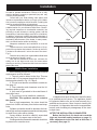
Adequate combustion and ventilation air must be
provided.
Place the stove on a noncombustible oor or UL ap-
proved oor protector that extends 6 inches to the front,
6 inches to the sides and 1 inch to the rear of the stove.
Fig. 8.
Place the stove away from combustible walls at least
as far as shown in gures 6, and 7.
Note that the clearances shown are minimum for
safety, but do not leave much room for access when
cleaning or servicing. Please take this into account when
placing the stove.
AFTER THE INSTALLATION IS COMPLETED
Beforetherstreislit,checkandrecordthe
high and low draft reading numbers on page 10.
Make adjustments to the low draft at this time, if
necessary. See page 10.
Installation
6"
6"
6" From Glass
Fig.8
When installing this stove in a mobile home several
requirements must be followed:
1. The unit must be bolted to the oor. This can
be done with 1/4" lag screws through the 2 holes in
the base plate shown in Fig. 13, Page 9.
2. The unit must also be connected to outside air.
See page 12.
3. Floor protection and clearances must be fol-
lowed as shown to right.
4. Unit must be grounded to the metal frame of
the mobile home.
5. The unit may not be installed in a bedroom.
CAUTION: This appliance must be vented to
the outside.
Due to high temperatures, the stove should be
placed out of trafc and away from furniture and drap-
eries.
Children and adults should be alerted to the haz-
ards of high surface temperatures and should stay away
to avoid burn to skin and/or clothing.
Young children should be carefully supervised
when they are in the same room as the stove.
Clothing and other ammable materials should not
be placed on or near the stove.
Fig.6
Fig.7
Installation and repair of this stove should be done
by a qualied service person. The appliance should
be inspected before use and at least annually by a
qualied service person. More frequent cleaning will
be required. It is imperative that control compartments,
burners, and circulating air passageways of the stove
be kept clean.
Mobile Home Installation
7"
7"
1"
10"
FLOOR
PROTECTOR
1"

9
Fig. 9
Fig.10
Fig.11
Fig.12
Fig.13
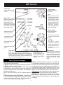
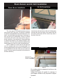
Side Door
Magnets
Removing Side Doors
Figure 9
Use hand hole to swing open side doors to at least
90
o
.
Figure 10
Remove side doors by lifting upward on the door until
the bottom pin is out of its hole. Move the bottom of
the door out and away from the pedestal base about
1/2". Allow the door to slide downward until the top
door pin is out of its top hole.
NOTE: Always remove the side doors and rear
shields to move the unit. This will keep them from
getting damaged.
Removing the Rear Motor Shield Sheet Metal.
NOTE: Disconnect power to the unit before
removing the motor shields. Danger of electrical
shock. Hot and moving parts could cause injury.
Figure 11
There are (2) #10 hex head screws holding each rear
shield. Using a 5/16" nut driver or socket, loosen the
(2) screws about 4 or 5 turns.
Figure 12
Slide the rear shields straight outward until the
ends come out of the rear retaining clips, as seen in
Fig.13.
There are two bolts holding the stove to the pallet (see
Fig. 23) Remove the bolts to move the stove.
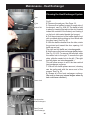
Placing Rear Shields Back on Unit
1. When replacing the shields, always insert the top
and bottom ends of the sheet metal into the retaining
clips rst.
2. Slide the shields straight inward until the (2) hex
head screws are fully inserted into the stove slots.
3. Make sure the top edges of the shield are against
the hopper bottom and tighten screws
.
The rear shields are split around the ue tail pipe
and outside air knockout. This allows removal and
installation of the rear shields with the unit completely
installed.
Rear Shield Retaining clip
Outside Air
Knockout
Pallet Hold Down Bolts
Side
Door
Side Door
Rear
Shield
Rear
Shield
Rear
Shield
Removing Side Doors for Installation

10
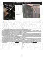
These units are pre-tested at the factory with exactly
120 Volts A.C., 60 Hz. They are checked and adjusted
for rebox tightness, gasket leakage, motor operation
and igniter operation. The Advance is then factory set
at a mid-point adjustment and in most cases will not
need any adjustments. NOTE: The factory low draft
setting may not be correct for the unit's permanent
installation conditions.
The control board on the Advance is equipped with a
low draft adjustment port, located on the control face just
to the right of the igniter light. See Figure 14. This voltage
adjustment is provided to allow the unit to be adjusted
for the household voltage where the unit is going to be
in permanent operation. NOTE: The line voltage varies
from area to area and often home to home.
The low draft voltage should be adjusted to achieve
the most efcient burn on low burn or "maintenance".
This voltage adjustment allows the installer to change
the low voltage set point approximately 15 volts. This
adjustment should be done by the installer during set
up because a draft meter reading is required to insure
proper set up.
If the unit is not adjusted properly, it does not cause
a safety concern. If the unit is adjusted too high, only
efency is lost. If the unit is adjusted too low, the low
draft pressure switch will not allow the feeder motor or
the igniter to operate.
A simple draft test should be performed after
completing the ue pipe installation. To record the
results for future reference:
1. Plug unit into a 120VAC, 60 HZ outlet.
2. Close the hopper lid, front view door, and the
ash pan. Neither pellets or a re are required for this
test.
3. With the mode selector in the "OFF" position, turn
the feed adjuster to "TEST".
4. Record the high draft_____in W.C. (Normal is -.50
to -.60) The control will be on the High Draft for a total
of 2 minutes.
5. After 2 minutes is up, the combustion motor will
go down to low draft and the distribution blower will
go on high. Allow approximately 15 seconds to pass
for the combustion motor to slow before checking the
low draft.
6. If the low draft is between .35 and .45, record the
reading _____ in W.C. If the reading is higher, slowly
turn the set screw counter-clockwise until the draft
lowers. If the reading is lower, very slowly turn the set
screw clockwise until the draft increases.
NOTE: The test mode alternates from high to low
draft every 60 seconds. If more time is needed
for draft adjustment, wait until the next low draft
cycle.
NOTE: In some cases, the draft may not go as low
as .35 even with the set screw completely counter-
clockwise.
Combustion
Motor Speed
Control
Low draft only
set point.
The small straight
screwdriver slot is
plastic; therefore,
the unit can be
adjusted while in
operation.
Fig.14
Draft Meter bolt hole location
Fig.15:
Low Draft Voltage Adjustment

11
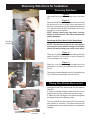
The room sensor is a small temperature sensor
on the end of a 60" gray wire. This sensor is installed
much like a standard wall thermostat. Because it is so
small, it can be hidden along the trim of a doorway or
even up the leg of a coffee table. There is a remote
room sensor port on the rear of the unit for easy ex-
ternal connection. Use standard 18-2 thermostat wire
to extend the distance to the desired location (100'
maximum). The room sensor should be installed in the
location where you want to control the temperature.
NOTE: Distances of more than 25 feet from the
unit or in another room are not recommended. It is
recommended that the room sensor be installed, even
if only installed on the rear of the unit as a return air
sensor. The room sensor is essential for the Advance's
excellent efciency.
Air Grill Installation
Do not allow pellets or sawdust to build up on the
hopper lid gasket.
Inspect the hopper lid gasket for damage. A
good hopper lid seal is very important for proper
operation.
REMINDERS
Fig. 18
Insert the two tail end hooks of the Air Grill Assembly
up under the stove top edge. Insert inward until the
two center hooks drop into the stove body slots in
the front of the unit.
Fig. 16
Fig. 17
Room Sensor and Air Grill Installation
Room Sensor Installation
Hopper Lid
Foam Gaskets

12
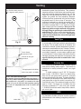
A combustion blower is used to extract the
combustion gases from the rebox. This causes a
negative pressure in the rebox and a positive pres-
sure in the venting system as shown in g. 19. The
longer the vent pipe and more elbows used in the
system, the greater the ow resistance. Because
of these facts we recommend using as few elbows
as possible and 15 feet or less of vent pipe. The
maximum horizontal run should not exceed 48". If
more than 15 feet of pipe is needed, the diameter
should be increased from 3" to 4" because a larger
pipe causes less ow resistance. Be sure to use
approved pellet vent pipe wall and ceiling pass-
throughttingstogothroughcombustiblewalls
and ceilings. Be sure to use a starting collar to at-
tach the venting system to the stove. The starting
collar must be sealed to the stove with high temp
silicone caulking.
HRV
When installing in a house with a Heat Reclaim-
ing Ventilation System (HRV) be sure the system is
balanced and is not creating a negative pressure in
the house.
Outside Air
Outside air is optional except in mobile homes
and where building codes require. The benet of
outside air is mainly noticed in small, very tight
houses.
To install outside air use 2 3/8" I.D. ex pipe
part number 1-00-08543. There is a break-away
hole on the rear panel which must be removed
before connecting the ex pipe. The pipe should be
run outside and terminate to the side or below the
vent pipe outlet so the ue outlet is more than 12"
from the inlet cover. The maximum length run of this
pipe is 15 feet. If a longer run is needed, the size
must be increased to 3". Inlet cover part number
1-10-08542 should be used to keep birds, rodents,
etc. out of pipe.
Fig.19
Venting
Vent Pipe
Pellet venting pipe ( also known as PL vent )
is constructed of two layers with air space between
the layers. This air space acts as an insulator and
reduces the outside surface temperature to allow a
clearance to combustibles of only 3 inches. The sec-
tions of pipe lock together to form an air tight seal in
most cases; however, in some cases a perfect seal
is not achieved. For this reason and the fact that the
Advance operates with a positive vent pressure, we
specify that the joints also be sealed with clear
silicone.
+ = Positive static pressure
= Negative static pressure
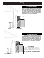
Direct Vent Wall Passthrough
The Harman Direct Vent Wall Passthrough (Part # 1-
00-677077) makes installing your Harman Pellet Stove
with outside air a lot easier. It is made to t walls
from 4 1/2" up to 10 1/8" thick with a square opening
of 6" to 6 1/2". Adjustable from 4 1/2" to 10 5/8" wall
thickness.
Inlet Cover part# 1-10-08542
Flex pipe part# 1-00-08543
Outside air ex pipe
goes here
Room Sensor
Connection Ports
Outdoor Half
Indoor Half

13
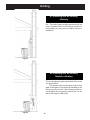
#2 Preferred method
This method also provides excellent venting for
normal operation but requires the stove to be installed
farther from the wall. The vertical portion of the vent
should be three to ve feet high and at least three inch-
es from a combustible wall. This vertical section will
provide natural draft in the event of a power failure.
#1 Preferred method
This method provides excellent venting for normal
operation and allows the stove to be installed closest
to the wall. One inch from the wall is safe; however,
two or three inches allows better access to remove the
rear panel. The vertical portion of the vent should be
three to ve feet high. This vertical section will provide
natural draft in the event of a power failure.
Fig.20
Fig.21
Venting
KEEP COMBUSTIBLES (SUCH AS
GRASS, LEAVES, ETC.) AT LEAST 3
FEET AWAY FROM THE FLUE OUTLET
ON THE OUTSIDE OF THE BUILDING.
CAUTION
3 ft.
to combustibles
3 ft.
to combustibles
3 ft.
to combustibles
3 ft.
to combustibles

14
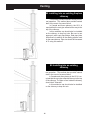
#3 Installing into an existing
chimney
This method can be used for normal opera-
tion. This method also provides natural draft in the
event of a power failure. If the chimney condition is
questionable you may want to install a liner as in
method #6.
#4 Installing into an existing
replacechimney
This method can be used for normal operation.
This method also provides natural draft in the event
of a power failure.
The damper area must be sealed with a steel
plate or berglass. A cap should be installed on the
chimney to keep out rain. If the chimney condition is
questionable you may want to install a liner all the
way to the top as in Method #5.
Fig.22
Fig.23
Venting

15
#5 Installing into an existing
replace
chimney
This method provides excellent venting for nor-
mal operation. This method also provides natural
draft in the event of a power failure.
In Canada and some places in the US it is
required that the vent pipe extend all the way to the
top of the chimney.
In this method a cap should also be installed
on the chimney to keep out rain. Be sure to use
approved pellet vent pipe ttings. Seal pipe joints
with silicone in addition to the sealing system used
by the manufacturer. Pipe size should be increased
to 4" using this method.
#6 Installing into an existing
chimney
This method provides excellent venting for nor-
mal operation. This method also provides natural
draft in the event of a power failure.
In Canada and some places in the US it is re-
quired that the vent pipe extend all the way to the top
of the chimney. The pipe or liner inside the chimney
should be 4" diameter.
In this method a cap should also be installed
on the chimney to keep out rain.
Fig.24
Fig.25
Venting

16
Venting
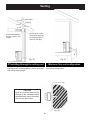
PL vent manufacturer's
firestop spacer and
support.
No insulation or other
combustible materials
are allowed within 3"
of the PL vent pipe.
#7 Installing through the ceiling vent
Through the ceiling vent, follow PL vent
manufacturer's recommendations when using wall
and ceiling pass through.
Flashing
Storm collar
12" min.
3" min.
3" min.
Fig. 26
Fig. 27
3" min.
Minimumueventconguration
It is recommended that outside air be installed with
this venting conguration.
18"
Fig. 28
12" min. wall to outlet
CAUTION
Keep any materials that may be
affected by the elevated exhaust
temperatures at least 3 feet away
from the ue termination.
min. above ground level

17
Venting
Requirements for Terminating the
Venting
WARNING: Venting terminals must not be re-
cessed into a wall or siding.
NOTE: Only PL vent pipe wall pass-throughs and
re stops should be used when venting through com-
bustible materials.
NOTE: Always take into consideration the effect
the prevailing wind direction or other wind currents
will cause with yash and /or smoke when placing the
termination.
In addition, the following must be observed:
A. The clearance above grade must be a minimum
of 18".
1
B. The clearance to a window or door that may be
opened must be a minimum of 48" to the side, 48" below
the window/door, and 12" above the window/door.
1
(with outside air installed, 18” below or beside,
and 9" above.)
C. A 12" clearance to a permanently closed win-
dow is recommended to prevent condensation on the
window.
D. The vertical clearance to a ventilated soft lo-
cated above the terminal within a horizontal distance of
2 feet (60 cm) from the center-line of the terminal must
be a minimum of 18".
E. The clearance to an unventilated soft must
be a minimum of 12".
F. The clearance to an outside corner is 11" from
center of pipe.
G. The clearance to an inside corner is 12".
H. A vent must not be installed within 3 feet (90 cm)
above a gas meter/regulator assembly when measured
from the horizontal center-line of the regulator.
1
I. The clearance to service regulator vent outlet
must be a minimum of 6 feet.
1
J. The clearance to a non-mechanical air supply
inlet to the building or the combustion air inlet to any
other appliance must be a minimum of 48”.
1
K. The clearance to a mechanical air supply inlet
must be a minimum of 10 feet.
1
(with outside air installed, 6 feet )
L. The clearance above a paved sidewalk or a
paved driveway located on public property must be a
minimum of 7 feet.
1,2
M. The clearance under a veranda, porch, deck
or balcony must be a minimum of 12 inches.
1,3
NOTE: The clearance to vegetation and other
exterior combustibles such as mulch is 36” as mea-
sured from the center of the outlet or cap. This 36”
radius continues to grade or a minimum of 7 feet below
the outlet.
1
Certain Canadian and or Local codes or regula-
tions may require different clearances.
2
A vent shall not terminate directly above a side-
walk or paved driveway which is located between two
single family dwellings and serves both dwellings.
3
Only permitted if veranda, porch, deck, or bal-
cony is fully open on a minimum of 2 sides beneath
the oor.
V
= Vent terminal
NOTE: Where passage through a wall, or partition
of combustible construction is desired, the
installation shall conform to CAN/CSA-B365. (if
in Canada)

18
DO NOT INSTALL A FLUE DAMPER IN THE
EXHAUST VENTING SYSTEM OF THIS
UNIT.
DO NOT CONNECT THIS UNIT TO A CHIMNEY
FLUE SERVING ANOTHER APPLIANCE.
INSTALL VENT AT CLEARANCES SPECIFIED
BY THE MANUFACTURER
Mobile home installation should be done
in accordance with the Manufactured
Home and Safety Standard (HUD), CFR
3280, Part 24.
MOBILE HOME REGULATIONS DO
NOT ALLOW INSTALLATION IN A
ROOM DESIGNATED FOR SLEEPING.
WARNING
KEEP COMBUSTIBLES AWAY
FROM FLUE OUTLET.
CAUTION
CAUTION
THE STRUCTURAL INTEGRITY OF THE
MOBILE HOME FLOOR, WALL, AND
CEILING/ROOF MUST BE MAINTAINED.
Keep combustible materials such as
grass, leaves, etc. at least 3 feet away
from the point directly under the vent
termination.
WARNING
Venting

19
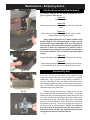
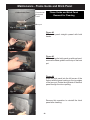
Ash Pan Removal and Reattachment
CAUTION: Surfaces are hot while in operation, Wear
gloves to protect from burns.
Figure 29
Open side doors.
Figure 30
Release spring latches on the right and left side of the ash
pan.
Figure 31
Slide ash pan forward enough to lift with center handle.
Empty ashes and reinstall ash pan.
Ashes should be placed in a metal container with
atightttinglid.Theclosedcontainerofashesshould
beplacedonanoncombustibleoororontheground,
wellawayfromallcombustiblematerials,pendingnal
disposal. If ashes are disposed of by burial in soil or
otherwise locally dispersed, they should be retained in
the closed container until all cinders have thoroughly
cooled.
Figure 32
Inspect the gasket rope for damage. Replace if necessary.
Figure 33
Insert spring latch front hooks into the ash pan side slots.
Push both latches to the rear at the same time to latch.
When removing the ash pan to empty ashes, you will
note a build up of ash nes behind the ash pan. This space
behind the ash pan was designed to allow the nes to fall
out of the vertical heat exchangers and collect where they
are easily cleaned out, rather than going into the ue pipe
where it would be difcult to clean. These nes should not
be allowed to build up. They may not allow the ash pan to
be seated into its gasket properly. NOTE: If an extreme
amount of force is required to snap the latch on one or
both sides of the ash pan, the area behind the ash pan
shouldbecheckedforashnebuildup.
Fig. 29
Fig. 30
Fig. 31
Fig. 32
Fig. 33
Maintenance - Emptying Ashes
Soot and Fly Ash
The products of combustion will contain small particles
of y ash. The y ash will collect in the exhaust venting
system and restrict the ow of the ue gases. Incomplete
combustion, such as occurs during startup, shutdown, or
incorrect operation of the room heater, will lead to some
soot formation which will collect in the exhaust venting sys-
tem. The ENTIRE venting system should be professionally
cleaned at least once each year.

20
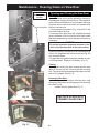
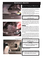
Opening and Closing the View Door
Opening:
The view door must be opened for cleaning of
the glass and scraping of the burn pot. This should be
done with the unit off and cool, in most cases. Although
the glass can be cleaned and burn pot scraped while
the unit is at low burn.
1. Using scraper as shown in Fig. 34 and 35, lift the
door latch forward and up.
2. Swing the door open to the left, stopping the swing
when resistance is felt. Forcing the door open further
then was designed may cause damage to the door or
it's hinges.
CAUTION
Do not put excessive downward pressure on the
latch end of the door while in the open position.
If the door is going to be opened for an extended period
of time, it is suggested that it be removed (see Fig. 36)
and set safely aside.
3. Inspect the door gasket and glass gaskets for worn
or missing pieces. Replace if necessary. (Fig. 37)
Closing:
When closing the door, always hold the door
latch all the way up until it has caught the receiving
bolt. Then push the latch downward and back until the
door is fully seated. See Fig. 35.
Removing View Door:
To remove the view door from the stove, hold
the door by the bottom and lift upward off of the hinge
pins.See Fig. 36.
Inspect the door gasket.See Fig. 37.
REPLACE GLASS WITH
CERAMIC GLASS ONLY.
Fig. 34
Fig. 35
Fig. 36
Fig. 37
Receiving Bolt
WARNING
Door latch may
be hot!
Maintenance - Cleaning Glass on View Door
La page est en cours de chargement...
La page est en cours de chargement...
La page est en cours de chargement...
La page est en cours de chargement...
La page est en cours de chargement...
La page est en cours de chargement...
La page est en cours de chargement...
La page est en cours de chargement...
La page est en cours de chargement...
La page est en cours de chargement...
La page est en cours de chargement...
-
 1
1
-
 2
2
-
 3
3
-
 4
4
-
 5
5
-
 6
6
-
 7
7
-
 8
8
-
 9
9
-
 10
10
-
 11
11
-
 12
12
-
 13
13
-
 14
14
-
 15
15
-
 16
16
-
 17
17
-
 18
18
-
 19
19
-
 20
20
-
 21
21
-
 22
22
-
 23
23
-
 24
24
-
 25
25
-
 26
26
-
 27
27
-
 28
28
-
 29
29
-
 30
30
-
 31
31


Harman Stove Company Advance Installation & Operating Manual
- Catégorie
- Poêles
- Taper
- Installation & Operating Manual
dans d''autres langues
- English: Harman Stove Company Advance
Documents connexes
Autres documents
-
United States Stove VG5501S Le manuel du propriétaire
-
US Stove Company 5501S Le manuel du propriétaire
-
-
-
-
-
Harman Accentra52i-TC Pellet Insert Le manuel du propriétaire
-
USSC Golden eagle 5520 Le manuel du propriétaire
-
-