La page est en cours de chargement...

R1
XXV Pellet Stove Owners Manual
SAVE THESE INSTRUCTIONS
Installation & Operating Manual
R4
“Ce manuel est disponible en Français sur demande”
SAFETY NOTICE
PLEASE READ THIS ENTIRE MANUAL BEFORE YOU INSTALL AND USE YOUR NEW ROOM HEATER. FAILURE
TO FOLLOW INSTRUCTIONS MAY RESULT IN PROPERTY DAMAGE, BODILY INJURY, OR EVEN DEATH.
FOR USE IN THE U.S. AND CANADA. SUITABLE FOR INSTALLATION IN MOBILE HOMES.
IF THIS HARMAN STOVE IS NOT PROPERLY
INSTALLED, A HOUSE FIRE MAY RESULT. FOR YOUR SAFETY,
FOLLOW INSTALLATION DIRECTIONS.
CONTACT LOCAL BUILDING OR FIRE OFFICIALS ABOUT RESTRICTIONS AND INSTALLATION INSPECTION
REQUIREMENTS IN YOUR AREA.
CONTACT YOUR LOCAL AUTHORITY (SUCH AS MUNICIPAL BUILDING DEPARTMENT, FIRE DEPARTMENT,
FIRE PREVENTION BUREAU, ETC.) TO DETERMINE THE NEED FOR A PERMIT.
CETTE GUIDE D'UTILISATION EST DISPONIBLE EN FRANCAIS. CHEZ VOTRE CONCESSIONNAIRE DE
HARMAN STOVE COMPANY.
# 3-90-00684

2
XXV Pellet Stove
Model: XXV
Residential Space Heating Appliance Fired by Wood Pellets
Also for use in Mobile Homes.
This pellet burning applicance has been tested and listed for use in
Manufactured Homes in accordance with OAR 814-23-900 through 814-23-909
“PREVENT HOUSE FIRES” Install and use only in accordance with manufacturer’s instal-
lation and operation instructions. Contact local building or fire officials about restrictions
and inspection in your area.
WARNING: FOR MANUFACTURED HOMES: Do not install appliance in a sleeping room. An
outside combustion air inlet must be provided. The structural integrity of the manufactured
home floor, ceiling and walls must be maintained.
Refer to manufacturer’s instructions and local codes for precautions required for passing
chimney through a combustible wall or ceiling. Inspect and clean exhaust venting system
frequently in accordance with manufacturer’s instructions.
Use a 3” or 4” diameter type “L” or “PL” venting system.
Do not connect this unit to a chimney flue servicing another appliance.
FOR USE WITH PELLETIZED WOOD FUEL ONLY.
Input Rating Max: 5.7 lb. fuel/hr.
Electrical Rating: 240 VAC, 50 Hz, Start 2.0 AMPS, Run 1.1 AMPS
U.S. Electrical Rating: 115 VAC, 60 Hz, Start 4.1 AMPS, Run 1.1 AMPS
Emission of CO in Combustion:
Nominal Heat Output: .02%, Reduced Heat Output: .04%
Flue Gas Temperature: 224 C
Thermal Output: 10.5kW
Energy Efficiency: Nominal: 84%, Reduced: 73%
Fuel Type: Wood Pellets, 5mm diameter, 20mm long
Route power cord away from unit.
DANGER: Rish of electrical shock. Disconnect power supply before servicing.
Replace glass only with 5mm ceramic available from your dealer.
For further instruction refer to owner’s manual.
Keep viewing and ash removal doors tightly closed during operation.
U.S. ENVIRONMENTAL PROTECTION AGENCY
This model is exempt from EPA certification under 40 CFR 60.531 by definition [Wood Heater (A) “Air-to-Fuel Ratio”].
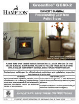
MINIMUM CLEARANCES TO
COMBUSTIBLES
Back Wall to Appliance 3”
Side Wall to Appliance 12”
Corner Installation
Walls to Appliance 6.25”
Alcove Installation
Min. Alcove Height 60”
Min. Alcove Side Wall 12”
Max. Alcove Depth 36”
FLOOR PROTECTION
Sides 2”/5 cm
Back 0”/0 cm
Front 6”/15 cm
Use a non-combustible floor protector
extending under unit and to the sides, front
and b
ack of unit as shown in Floor Protec
tion
Diagram. Measure front distance from the
surface of the glass door.
Recommended: Non-combustiblle floor
protection extending beneath the fluepipe
when installed with horizontal venting or
under the top vent adapter with vertical
installation.
3”
12”
6.25”
6.25”
5”min.
5”min.
6”
0”
32” minimum
32” minimum
2”
2”
12”
12”
36”
Do not remove this label/Ne pas enlever cette étiquette. Made in USA/Fabriqué aux
AGENCE AMÉRICAINE POUR LA PROTECTION DE L’ENVIRONNEMENT
Ce modéle est dispensé par EPA certification d’après 40 CFR 60.531 par dèfinition [Appareil
à bois(A) Ratio air/combusiton]
OMNI-Test Laboratories, Inc.
Report #/Rapport #135-S-14-2
Test to/Testé à
ASTM E 1509-04, and ULC-C1482-M91
Tested by Emitech, Apave & BFP Electronique
EN60335-1, EN55014-1, EN 61000-3-2, EN 14785:2005
Test date: February 2004
Room Heater Pellet Fuel Burning type (UM) 84-HUD
2005
2006
2007
APR
MAR
FEB
MAY
JAN
JUN
JUL
AUG
SEPT
OCT
NOV
DEC
Date of Manufacture/Date de Fabrication:
Ne pas enlever cette étiquette. Fabriqué par: Harman Stove Company 352 Mountain House Road, Halifax, P
A 17032 Fabriqué aux USA
Modèle: XXV
Appareil de chauffage à granulés de bois
DANGER : Risque d’électrocution. Débrancher l’appareil avant toute intervention.
Ne remplacer la vitre qu’avec une vitre céramique de 5 mm de même qualité disponible
auprès de votre revendeur.
Pour une information plus complète, se reporter à la notice d’utilisation.
Tenir la porte frontale et le couvercle de trémie hermétiquement clos durant le
fonctionnement de l’appareil.
Puissance calorifique émise
Nominale: 10,5 Kw Réduite: 1,8 Kw
Concentration CO (à 13 % O2)
à puissance nominale : 0,02 % à puissance réduite : 0,04 %
Rendement
à puissance nominale : 84 % à puissance réduite : 73 %
DISTANCES DE SECURITE PAR RAPPORT AUX MATERIAUX COMBUSTIBLES
Entre mur arrière et appareil 8 cm
Entre paroi latérale t appareil
31 cm
Installation en angle
Entre murs et appareil
16 cm
Installation en alcôve
Hauteur minimale de l’alcôve
150 cm
Parois latérales de l’alcôve
31 cm
Profondeur maximale de l’alcôve
91 cm
PROTECTION DU PLANCHER
Côtés
5 cm
Arrière
0 cm
Avant
15 cm
Utiliser une protection de sol non combustible sous l’appareil qui s’étend sur les côtés,
l’avant et l’arrière du poêle (voir schéma). Pour la distance à l’avant, mesurer à partir
de la surface de la porte en verre.
Il est recommandé que la protection s’étende jusque sous le conduit en cas d’installation
d’un conduit horizontal ou sous le té en cas de conduit vertical.
PREVENTION DES INCENDIES
Respecter scrupuleusement les instructions du constructeur pour l’installation et
les consignes de fonctionnement. Respecter les règles de sécurité en vigueur
dans votre région.
AVERTISSEMENT POUR MOBILE HOMES : Ne pas installer dans une chambre. Il
est impératif de prévoir une prise d’air extérieur. L’intégrité structurale du plancher,
du plafond et des murs doit être strictement préservée.
Se reporter aux instructions du fabricant et aux réglementations spécifiques locales
concernant les précautions requises lors de la traversée d’un mur ou d’un plafond.
Contrôler et nettoyer fréquemment tout le système d’évacuation des fumées
conformément aux recommandations du constructeur.
Utiliser des conduits « Spécial granulés » de diamètre 80 mm ou 100 mm.
Ne pas raccorder ce poêle à un conduit de cheminée déjà utilisé pour un autre
appareil de chauffage.
FONCTIONNE EXCLUSIVEMENT AVEC DES GRANULES DE BOIS.
SE CONFORMER AUX INSTRUCTIONS D’UTILISATION
Consommation maximale: 2,9 kg/h
Caractéristiques électriques: 240 VC, 50 Hz, Intensité au démarrage 2 A, Intensité
fonctionnement normal 1,1 A
Tenir le cordon d’alimentation à l’écart du poêle.
Tests réalisés par OMNI TEST LABORATORIES, Inc.
Rapport N
o
135-S-14-2
Essais selon les normes 1509-04 de l’ASTM et C 1482-M91ULC
Appareil de chauffage
à
granu
lés (UM) 84-HUD
NORMES EUROPEENNES:
NF EN 14785 CETIAT – Déc. 2006
AEMC MESURES EN50366 - Déc. 2006
EMITECH, APAVE & BFP
Electronique
- Fév. 2004
EN
55014-1, EN 55014-2, EN 61000-3-2, EN 61000-3-3
Serial No.
N° de série

3
XXV Pellet Stove
Please read this entire manual before you install
and use your new room heater. Failure to fol-
low instructions may result in property damage,
bodily injury, or even death.
Harman Home Heating
352 Mountain House Road
Halifax, PA 17032
Model: XXV
Residential Space Heating Appliance Fired by Wood Pellets
Also for use in Mobile Homes.
This pellet burning applicance has been tested and listed for use in
Manufactured Homes in accordance with OAR 814-23-900 through 814-23-909
“PREVENT HOUSE FIRES” Install and use only in accordance with manufacturer’s instal-
lation and operation instructions. Contact local building or fire officials about restrictions
and inspection in your area.
WARNING: FOR MANUFACTURED HOMES: Do not install appliance in a sleeping room. An
outside combustion air inlet must be provided. The structural integrity of the manufactured
home floor, ceiling and walls must be maintained.
Refer to manufacturer’s instructions and local codes for precautions required for passing
chimney through a combustible wall or ceiling. Inspect and clean exhaust venting system
frequently in accordance with manufacturer’s instructions.
Use a 3” or 4” diameter type “L” or “PL” venting system.
Do not connect this unit to a chimney flue servicing another appliance.
FOR USE WITH PELLETIZED WOOD FUEL ONLY.
Input Rating Max: 5.7 lb. fuel/hr.
Electrical Rating: 240 VAC, 50 Hz, Start 2.0 AMPS, Run 1.1 AMPS
U.S. Electrical Rating: 115 VAC, 60 Hz, Start 4.1 AMPS, Run 1.1 AMPS
Emission of CO in Combustion:
Nominal Heat Output: .02%, Reduced Heat Output: .04%
Flue Gas Temperature: 224 C
Thermal Output: 10.5kW
Energy Efficiency: Nominal: 84%, Reduced: 73%
Fuel Type: Wood Pellets, 5mm diameter, 20mm long
Route power cord away from unit.
DANGER: Rish of electrical shock. Disconnect power supply before servicing.
Replace glass only with 5mm ceramic available from your dealer.
For further instruction refer to owner’s manual.
Keep viewing and ash removal doors tightly closed during operation.
U.S. ENVIRONMENTAL PROTECTION AGENCY
This model is exempt from EPA certification under 40 CFR 60.531 by definition [Wood Heater (A) “Air-to-Fuel Ratio”].
MINIMUM CLEARANCES TO
COMBUSTIBLES
Back Wall to Appliance 3”
Side Wall to Appliance 12”
Corner Installation
Walls to Appliance 6.25”
Alcove Installation
Min. Alcove Height 60”
Min. Alcove Side Wall 12”
Max. Alcove Depth 36”
FLOOR PROTECTION
Sides 2”/5 cm
Back 0”/0 cm
Front 6”/15 cm
Use a non-co mbustibl e fl oor protecto r
extending under unit and to the sides, front
and b
ack of unit as shown in Floor Protec
tion
Diagram. Measure front distance from the
surface of the glass door.
Recommended: Non-combu stiblle floor
protection extending beneath the fluepipe
when installed with horizontal venting or
under the top v ent adapter with vertical
installation.
3”
12”
6.25”
6.25”
5”min.
5”min.
6”
0”
32” minimum
32” minimum
2”
2”
12”
12”
36”
Do not remove this label/Ne pas enlever cette étiquette. Made in USA/Fabriqué aux
AGENCE AMÉRICAINE POUR LA PROTECTION DE L’ENVIRONNEMENT
Ce modéle est dispensé par EPA certification d’après 40 CFR 60.531 par dèfinition [Appareil
à bois(A) Ratio air/combusiton]
OMNI-Test Laboratories, Inc.
Report #/Rapport #135-S-14-2
Test to/Testé à
ASTM E 1509-04, and ULC-C1482-M91
Tested by Emitech, Apave & BFP Electronique
EN60335-1, EN55014-1, EN 61000-3-2, EN 14785:2005
Test date: February 2004
Room Heater Pellet Fuel Burning type (UM) 84-HUD
2005
2006 2007
APR
MARFEB
MAY
JAN
JUN
JUL
AUG
SEPT
OCT
NOV
DEC
Date of Manufacture/Date de Fabrication:
Ne pas enlever cette étiquette. Fabriqué par: Harman Stove Company 352 Mountain House Road, Halifax, P
A 17032 Fabriqué aux USA
Modèle: XXV
Appareil de chauffage à granulés de bois
DANGER : Risque d’électrocution. Débrancher l’appareil avant toute intervention.
Ne remplacer la vitre qu’avec une vitre céramique de 5 mm de même qualité disponible
auprès de votre revendeur.
Pour une information plus complète, se reporter à la notice d’utilisation.
Tenir l a port e front ale et le couvercle de trémie hermétique ment cl os dura nt le
fonctionnement de l’appareil.
Puissance calorifique émise
Nominale: 10,5 Kw Réduite: 1,8 Kw
Concentration CO (à 13 % O2)
à puissance nominale : 0,02 % à puissance réduite : 0,04 %
Rendement
à puissance nominale : 84 % à puissance réduite : 73 %
DISTANCES DE SECURITE PAR RAPPORT AUX MATERIAUX COMBUSTIBLES
Entre mur arrière et appareil 8 cm
Entre paroi latérale t appareil
31 cm
Installation en angle
Entre murs et appareil
16 cm
Installation en alcôve
Hauteur minimale de l’alcôve
150 cm
Parois latérales de l’alcôve
31 cm
Profondeur maximale de l’alcôve
91 cm
PROTECTION DU PLANCHER
Côtés
5 cm
Arrière
0 cm
Avant
15 cm
Utiliser une protection de sol non combustible sous l’appareil qui s’étend sur les côtés,
l’avant et l’arrière du poêle (voir schéma). Pour la distance à l’avant, mesurer à partir
de la surface de la porte en verre.
Il est recommandé que la protection s’étende jusque sous le conduit en cas d’installation
d’un conduit horizontal ou sous le té en cas de conduit vertical.
PREVENTION DES INCENDIES
Respecter scrupuleusement les instructions du constructeur pour l’installation et
les consignes de fonctionnement. Respecter les règles de sécurité en vigueur
dans votre région.
AVERTISSEMENT POUR MOBILE HOMES : Ne pas installer dans une chambre. Il
est impératif de prévoir une prise d’air extérieur. L’intégrité structurale du plancher,
du plafond et des murs doit être strictement préservée.
Se reporter aux instructions du fabricant et aux réglementations spécifiques locales
concernant les précautions requises lors de la traversée d’un mur ou d’un plafond.
Contrôler et nettoy er fréquemment tout le système d’évacuation des fumées
conformément aux recommandations du constructeur.
Utiliser des conduits « Spécial granulés » de diamètre 80 mm ou 100 mm.
Ne pas raccorder ce poêle à un conduit de cheminée déjà utilisé pour un autre
appareil de chauffage.
FONCTIONNE EXCLUSIVEMENT AVEC DES GRANULES DE BOIS.
SE CONFORMER AUX INSTRUCTIONS D’UTILISATION
Consommation maximale: 2,9 kg/h
Caractéristiques électriques: 240 VC, 50 Hz, Intensité au démarrage 2 A, Intensité
fonctionnement normal 1,1 A
Tenir le cordon d’alimentation à l’écart du poêle.
Tests réalisés par OMNI TEST LABORATORIES, Inc.
Rapport N
o
135-S-14-2
Essais selon les normes 1509-04 de l’ASTM et C 1482-M91ULC
Appareil de chauffage
à granu
lés (UM) 84-HUD
NORMES EUROPEENNES:
NF EN 14785 CETIAT – Déc. 2006
AEMC MESURES EN50366 - Déc. 2006
EMITECH, APAVE & BFP
Electronique
- Fév. 2004
EN55014-1, EN 55014-2, EN 61000-3-2, EN 61000-3-3
Serial No.
N° de série
Assembly & Installation 4
Installation 5
Venting 6
ESP Control 14
Low Draft Voltage Adjustment 15
Automatic Operation 16
Manual Operation 19
Room Sensor 21
Maintenance 22
Options 26
Trouble Shooting 27
Feeder Parts 28
Specications 29
Wiring Diagram 30
Parts List 31
Warranty 32
Table of Contents
Introduction
Thank you for purchasing the Harman XXV Pellet Stove. The Harman XXV Pellet Stove is the culmination
of elegance, convenience, functionality and dependability
The XXV was thoughtfully designed to look captivating in every home. Intricately detailed oak leaves
express the magnitude of craftsmanship that goes into making this stove a masterpiece. These beautiful
castings are proudly made in the U.S.A.
Built to strict Harman standards, the XXV has the most advanced construction of any Harman Pellet Stove.
This 25th Anniversary Stove is based on Harman's patented pellet stove technology and goes a few steps
further. The glass hopper lid allows you to see the fuel level while the mirrored front glass transforms into
clearglasswiththeradianceofthere.
A new concept for the XXV is the ability to use the top vent option. Using this method, the XXV can easily
replace a wood stove by placing the top vent adapter over the rear vent.
We put all of our favorite features into the XXV, fusing the highest caliber pellet stove innovations with
the allure of cast iron.
This label is located on the back of the unit.
Please copy the Serial Number for future reference.
Serial #:

4
XXV Pellet Stove
CAUTION
HOT WHILE IN OPERATION. KEEP
CHILDREN, CLOTHING AND FURNITURE
AWAY. CONTACT MAY CUASE SKIN
BURNS.
DO NOT INSTALL A FLUE DAMPER IN THE
EXHAUST VENTING SYSTEM OF THIS UNIT.
DO NOT CONNECT THIS UNIT TO A CHIMNEY
FLUE SERVING ANOTHER APPLIANCE.
CAUTION
KEEP COMBUSTIBLE MATERIALS (SUCH
AS GRASS, LEAVES, ETC.) AT LEAST 3
FEET AWAY FROM THE FLUE OUTLET
ON THE OUTSIDE OF THE BUILDING.
IMPORTANT NOTES
Flame Guide
Install the cast iron ame guide on top of the burn
pot.Makesurethattheameguideisfullyseatedon
the vertical sides of the burn pot and that the back of
the guide rests against
the burn pot mounting
ange.
Install the exhaust
/ v e n t i n g a t t h e
clearances specified
b y t h e v e n t i n g
manufacturer. Some
brands of pellet venting
require a 3" clearance
to combustibles, while
other brands require
only one inch.
Figure 1
The power cord is tucked inside the left rear cover
panel. To remove cord, Loosen the two 5/16" hex
heads and slide the panel outward.
Assembly and Installation
Due to high temperatures, the stove should be
placedoutoftrafcand awayfromfurnitureand
draperies.
Children and adults should be alerted to the haz-
ards of high surface temperatures and should stay
away to avoid burns to skin and/or clothing.
Young children should be carefully supervised
when they are in the same room as the stove.
Clothingandotherammablematerialsshould
not be placed on or near this unit.
Installation and repair of this Harman stove
shouldbedonebyaqualiedserviceperson.We
recommend that the stove be inspected before use
andatleastannuallybyaqualiedserviceperson.
Periodic cleaning is required throughout the heat-
ing season and at the end of each winter for the
stovetoworkefciently.Seecleaninginstructions
on page 22.

5
XXV Pellet Stove
Installing
Place the stove on a non-combustible oor
protector that extends a minimum of 6 inches
tothefront,2inchestothesidesandushwith
the rear of the hopper. Ash protection must also
be positioned under any horizontally run ue
pipe.Theminimumoorprotectormaterialis20
gaugesheetmetal.Otheroorprotectormateri-
als are ceramic tile, stone, brick, etc.
Place the stove away from combustible walls
at least as far as shown in Figures 2, 3 and 4.
Note that the clearances shown are minimum
for safety but do not leave much room for access
when cleaning or servicing. Please take this into
account when placing the stove.
Connect the power cord to a 120 V.A.C. 60Hz
grounded receptacle. (A surge protector is recommended to
protect the circuit board.) If the voltage entering your home
is below 116 volts your stove may not work properly. Also be
sure that the polarity of the outlet that the stove is plugged
into is correct.
Priortoinstallingtheuepipe,connectadraftmeter.(The
draft meter must have a minimum range of 0-.5.)Record the
rstreading.Connectuepipetostoveandbesurealldoors
and windows in the home are closed. Record the second
draft reading_______. If the second reading is more than .05"
lowerthantherstreading,checkforpossiblerestrictionsor
the need for outside air (see page 8). For more information
on the draft test procedure, refer to Page 20.
Mobile Home Installation
When installing this unit in a mobile home several re-
quirements must be followed
(Reference HUD Regulation
#24CFR3280)
:
1.Theunitmustbeboltedtotheoor.Thiscanbedoneby
using clips (part # 2-0-677110) and 1/4" lag screws.
2. The unit must also be connected to outside air. See
page 8.
3. Floor protection and clearances must be followed as
shown.
4. Unit must be grounded to the metal frame of the mobile
home.
CAUTION: This appliance must be vented to the out-
side.
4" from
back of top
ueventto
wall
18"
Fig. 5: Optional Top Vent Pipe Clearances
Fig. 2
6.25"
6.25"
Installation
Fig. 3
12"
3"
Floor Protection must be 2 inches to each side, 6
inches to the front, and 0 inches to the back of the
stove. Floor Protector minimum: 32" wide x 32"
deep.
Fig. 4
0"
32" minimum
32 minimum
2" from
side of
stove to
combustible
surface
6" from
glass
6" from
pipe to wall
Mobile home regulations do not allow
installation in a room designated for
sleeping.
WARNING
CAUTION
THE STRUCTURAL INTEGRITY OF THE
MOBILE HOME FLOOR, WALL, AND
CEILING/ROOF MUST BE MAINTAINED.

6
XXV Pellet Stove
Venting
Requirements for Terminating the Venting
WARNING: Venting terminals must not be recessed
into a wall or siding.
NOTE: Only the Harman Direct Vent Wall Pass-through
(part # 1-00-677077) or PL listed vent pipe wall pass-
throughsandrestopsshouldbeusedwhenventing
through combustible materials.
NOTE: Always take into consideration the effects of
the prevailing wind direction or other wind currents
thatmaycauseyashand/orsmokewhenplacingthe
termination vent.
In addition, the following must be observed:
A. The clearance above grade must be a minimum
of 18".
1
B. The clearance to a window or door that may be
opened must be a minimum of 48" to the side, 48"
below the window/door, and 12" above the window/
door.
1
(with outside air installed, 18” to side or below
window/door)
C. A 12" clearance to a permanently closed win-
dow is recommended to prevent condensation on
the window.
D.Theverticalclearancetoaventilatedsoftlo-
cated above the terminal within a horizontal distance
of 2 feet (60 cm) from the center-line of the terminal
must be a minimum of 18".
E.Theclearancetoanunventilatedsoftmustbe
a minimum of 12".
F. The clearance to an outside corner is 11" from
center of pipe.
G. The clearance to an inside corner is 12".
H. A vent must not be installed within 3 feet (90 cm)
above a gas meter/regulator assembly when measured
from the horizontal center-line of the regulator.
1
I. The clearance to service regulator vent outlet
must be a minimum of 6 feet.
1
J. The clearance to a non-mechanical air supply
inlet to the building or the combustion air inlet to any
other appliance must be a minimum of 48”.
1
K. The clearance to a mechanical air supply inlet
must be a minimum of 10 feet.
1
(with outside air installed, 6 feet )
L. The clearance above a paved sidewalk or a
paved driveway located on public property must be
a minimum of 7 feet.
1,2
M. The clearance under a veranda, porch, deck
or balcony must be a minimum of 12 inches.
1,3
NOTE: The clearance to vegetation and other exte-
rior combustibles such as mulch is 36” as measured
from the center of the outlet or cap. This 36” radius
continues to grade or a minimum of 7 feet below
the outlet.
1
Certain Canadian and or Local codes or regula-
tions may require different clearances.
2
A vent shall not terminate directly above a side-
walk or paved driveway which is located between
two single family dwellings and serves both dwell-
ings.
3
Only permitted if veranda, porch, deck, or bal-
cony is fully open on a minimum of 2 sides beneath
theoor.
NOTE: Where passage through a wall, or
partition of combustible construction is desired,
the installation shall conform to CAN/CSA-B365.
(if in Canada)
V
= Vent terminal

7
XXV Pellet Stove
Venting
A combustion blower is used to extract the
combustiongasesfromtherebox.Thiscausesa
negativepressureinthereboxandapositivepres-
sure in the venting system as shown in Fig. 6. The
longer the vent pipe and more elbows used in the
system, the greater the ow resistance. Because
of these facts we recommend using as few elbows
as possible and 15 feet or less of vent pipe. The
maximum horizontal run should not exceed 48".
If more than 15 feet of pipe is needed, the interior
diameter should be increased from 3" to 4" because
alargerpipecauseslessowresistance.Be sure
to use approved pellet vent pipe wall and ceiling
pass-through ttings to go through combustible
walls and ceilings. The use of a starting collar is
notalwaysnecessary.Therstpieceofpipeshould
be fastened securely with at least 2 fasteners to the
uecollarofthestove.Ifastartingcollarisusedto
attach the venting system to the stove, the starting
collar must be sealed to the stove with high temp
silicone caulking.
Vent Pipe
Pellet venting pipe (Known as "L" or "PL" vent-
ing) is constructed of two layers with air space
between the layers. This air space is an insulator
which reduces the surface temperature and allows
a clearance to combustibles of 3 inches or less. The
sections of pipe lock together to form an air tight seal
in most cases. However, in some cases a perfect
seal is not achieved. For this reason and the fact that
the XXV operates with a positive vent pressure we
specify that the joints also be sealed with silicone.
Aluminum tape can also be used for any joint that is
1 ft. or more from the outlet of the stove.
When using the top vent option, 6 inch single
wall pipe must be connected with at least three (3)
screws. Also, the joints must be sealed with high
temperature silicone.
We cannot emphasize enough, the importance of
sealing every seam and joint in the venting system
which is inside the home. Even the smallest pin hole
can leak and when it does you will smell wood smoke
or a creosote smell in the room. If this occurs check
for leaks. Leaks are easiest to see during start-up.
Alternatively you can use a smoke pellet to leak test
theventingbeforelightingyourrstre.
Venting
IMPORTANT NOTICE
Pellet Vent Pipe or PL Vent Pipe Must Be Used
unless the unit is being installed with the optional
top 6" Flue Adapter.
If using 6" Flue Adapter, it is recommended to
useasealedseam6"uepipe(snaplockseam
is not recommended) and seal the joints with high
temperature silicone.
In some cases it may be necessary to use a liner
in the existing chimney to obtain proper draft.
= Positive Static Pressure
= Negative Static Pressure
+
-
Fig. 6
CAUTION
Do not connect to any air distribution duct
or system.

8
XXV Pellet Stove
Outside air ex pipe
goes here.
Inlet Cover part#
1-10-08542
Flex pipe part#
1-00-08543 (25')
Outside Air
Here arefourbenetsof outside air:
1. Having air introduced from outside the living area
booststheoverallthermalefciency.
2. It eliminates draft problems that can occur in tight
homes.
3. It reduces the chance for smoke spillage in the
event of a power failure.
4. It allows your vent termination to be as close as
18" from windows or doors.
Outside air is optional except in mobile homes and
wherebuildingcodesrequire.Thebenetofoutside
air is mainly noticed in small, very tight, houses.
To install outside air use 2 3/8" I.D. non-
combustibleexpipe.Thereisabreak-awayhole
on the rear panel of the XXV stove which must be
removedbeforeconnectingtheexpipe.The pipe
should be run outside and terminate to the side or
belowtheventpipeoutletsotheueoutletismore
than 12" from the inlet cover. The maximum length
run of this pipe is 15 feet. If a longer run is needed
the size must be increased to 3". Inlet cover part
number 1-10-08542 should be used to keep birds,
rodents, etc.out of the pipe unless the Harman wall
passthrough is being used.
Direct Vent Wall Passthrough
The Harman Direct Vent Wall Passthrough (Part
# 1-00-677077) makes installing your Harman Pel-
let Stove with outside air a lot easier. It combines
the needed wall protection for the venting, with a
sourceofintakeairforcombustion.Itismadetot
walls from 4 1/2" to 10 1/8" thick with a single square
opening in the wall of 6-1/2 inches.
HRV
When installing in a house with a Heat Reclaim-
ing Ventilation System (HRV) be sure the system is
balanced and is not creating a negative pressure in
the house.
Venting
Fig. 7
Fig. 8
Outdoor Half
Indoor Half
Adjustable from 4 1/2" to 10 5/8" wall thickness

9
XXV Pellet Stove
#1 Preferred method
This method provides excellent venting for nor-
mal operation and allows the stove to be installed
closest to the wall. Two inches from the wall is
safe; however, four inches allows better access to
remove the rear panel. The vertical portion of the
ventshouldbethreetovefeethigh.Thisvertical
section will help provide natural draft in the event of
a power failure. Note: Do not place joints within
wall pass-throughs.
Venting
Fig. 9
3 ft.
to combustibles
Fig. 10
12" min. wall to outlet
3 ft.
to combustibles
3 ft.
to combustibles
3 ft.
to combustibles
NOTICE
A chimney connector shall not pass through an attic or roof space, closet or similar
concealed space, or a oor, or ceiling.
Fig. 11
#2 Preferred method
This method also provides excellent venting for
normal operation but requires the stove to be in-
stalled farther from the wall. The vertical portion of
theventshouldbethreetovefeethighandatleast
three inches from a combustible wall. This vertical
section will provide natural draft in the event of a
power failure.
If the stove is installed below grade be sure the
vent termination is at least 18" above grade. The
outlet must also be 1 foot from the house/building.
Note: Do not place joints within wall pass-
throughs.
CAUTION
Keep any materials that may be affected by the
elevated exhaust temperatures at least 3 feet
away from the ue termination.

10
XXV Pellet Stove
#3 Installing into an existing
chimney
This method provides excellent venting for nor-
mal operation. This method also provides natural
draft in the event of a power failure. If the chimney
condition is questionable* you may want to install a
liner as in method #6.
*The chimney should be inspected and cleaned
before installing your stove. If you discover that
the chimney does not have a clay tile liner or has
cracks or aking of the tile liner you will need to
install a stainless steel liner within the chimney. In
most cases the inside diameter of this liner should
be4".Eitherexibleorrigidlinermaybeusedfor
this purpose. Refer to Method 6.
Be sure to design the venting so that it can be
easily cleaned.
Fig. 12
Fig. 13
Venting
#4 Installing into an existing chimney
with optional top discharge 6" ue
adapter
Thismethodwillallowsinglewall6"uepipeto
come off the top of the stove and go directly into a
masonry or class A chimney.
This method will be desireable for people who are
replacing a wood or coal stove and have an existing
chimney to use.
6" from
pipe to wall

11
XXV Pellet Stove
#5 Installing into an existing replace
chimney (US and Canada)
This method provides excellent venting for normal
operation. This method also provides natural draft in
the event of a power failure.
Some places in the US and Canada it is required
that the vent pipe extend all the way to the top of the
chimney. Per ULC S628.
In this method a cap should also be installed on
the chimney to keep out rain. Be sure to use ap-
provedpelletventpipettings.Sealpipejointswith
silicone or aluminum tape in addition to the sealing
system used by the manufacturer. Pipe size should
be increased to 4" using this method.
#6 Installing into an existing
chimney (US and Canada)
This method provides excellent venting for normal
operation. This method also provides natural draft
in the event of a power failure.
In this method a 4 inch liner is installed the entire
lengthoftheue.Whetherusingarigidorexible
liner, a cap should be installed on the chimney to
keep out rain.
Fig. 14
Fig. 15
Venting

12
XXV Pellet Stove
#7 Installing into an existing chimney
using 3" pellet vent in combination
with 6" or 8" single or double wall
stove pipe.
This method allows the installer to use 6" or 8"
single and double wall stove pipe ( sealed seam not
snap lock ) and
an existing masonry or class A chimney to vent the
stove.
The stove must use pellet vent and 90 degree
elbow to start at the stove connector and then use
the approved pipe adapter to connect to the size
of vent that continues into the chimney connector.
Support of the assembly must follow any pipe and
connector manufacturers recommendations.
Due to combustible fuel, vent pipe to hopper
clearances must meet guidelines stated by NFPA
or local codes.
#8 Installing through the ceiling
Through the ceiling vent, follow vent manufacturers
recommendations when using a wall or ceiling pass
through. Note: Do not place joints within wall
pass-throughs.
Fig. 17
PL vent manufacturer's
fi re st op s pa cer an d
support
Storm collar
Flashing
3" min.
3" min.
12" min.
3" min.
3" min.
No insulation or
other combustible
m a t e r i a l s a r e
allowed within 3" of
the PL vent pipe.
Venting
Fig. 16

13
XXV Pellet Stove
Minimum flue vent
conguration
It is recommended that outside
air be installed with this venting
congurationtoreducesmoke
and creosote smell in the room
in the event of power failure.
18"
Venting
Fig. 18
Min. above ground level
12" min.
wall to outlet
36" min clearance
to any materials that
may be affected by
the elevated exhaust
temperatures
Fig. 19

14
XXV Pellet Stove
AUTOMATIC IGNITION ESP CONTROL
Power Light
Indicates power to the control.
Status Light
Will be lit in either stove
or room temp mode when
pointer is not within off
position band except
after normal shut down.
Blinks to indicate errors
listed below.
Status light error messages:
1 Blink: Indicates control board self diagnostic fail-
ure. This requires a manual reset*.
3 Blinks: Indicates ESP (Exhaust Sensing Probe)
failure. This requires a manual reset*.
4 Blinks: Can occur only in Room Temp Mode and
indicates Room Sensing Probe failed or not installed.
If a Room Sensing Probe is then installed, the status
light will automatically reset.
5 Blinks (In Igniter Auto. Mode Only): Indicates
that the unit has failed to light within the 36 minute
start cycle. To reset - Turn Mode Selector to "OFF",
then turn to either mode again.
6 Blinks : Indicates that the control has calculated
poor or incomplete combustion occurring for more
than 50 minutes.
A six blink status may be set if the stove is allowed
to run out of pellets. To reset, turn mode selector to
"OFF" then back on to the desired mode. If the unit
was not out of pellets, see Troubleshooting section,
Page 26, for more details.
* Manual reset- disconnect the power cord for a few
seconds and reconnect. If error still occurs call your
Dealer. Note: some early circuit boards will blink
the status light upon power-up. An error message is
a continuous blink cycle.
Di str ibut ion B low er
speed adjustment range.
L = low
H = high
Variable speed anywhere
between L and H; although
as the stove temp. goes
up, so does the low end
of the scale.
Temp dial
Allows you to adjust the
room temperature in
Room Temp Mode using
the outer scale marked
in degrees Fahrenheit. It
also allows you to adjust
the stove temperature
while in Stove Temp
Mode using the inner
scale marked from 1
to 7.
Mode Selector
Allows you to choose
be tw een R oo m Temp
Mode, Stove Temp Mode,
or OFF. Also allows you to
vary the distribution blower
speed by turning the knob
to the high or low side of
each mode.
Dealer Diagnostic Port
For dealer maintenance
only. Requires special DDM
monitor supplied to Harman
Dealers exclusively.
Feed adjuster
Sets the maximum feed rate
per each cycle of the control.
Igniter switch
Set to appropriate Start-
Up mode.
Test
Runs all motors at full
speed for one minute to
check operation. After two
minutes the stove will go
to minimum draft and the
blowers will alternate from
high to low every minute
to remind you that you are
still in "Test Mode".
Indicates power to the
igniter
Indicates power to the
feed motor.
Indicates power to
combustion blower
Indicates power to
distribution blower.

15
XXV Pellet Stove
These units are pre-tested at the factory with exactly
120 Volts A.C., 60 Hz. They are checked and adjusted
forreboxtightness,gasketleakage,motoroperation
and igniter operation. The XXV is then factory set at a
mid-point adjustment and in most cases will not need any
adjustments. NOTE: The factory low draft setting may
not be correct for the unit's permanent installation
conditions.
The control board on the XXV is equipped with a low
draft adjustment port. Located on the control face just
to the left of the igniter light. This voltage adjustment
is provided to allow the unit to be adjusted for the
household voltage where the unit is going to be in
permanent operation. NOTE: The line voltage varies
from area to area and often home to home.
The low draft voltage should be adjusted to achieve
themostefcientburnonlowburnor"maintenance".
This voltage adjustment allows the installer to change
the low voltage set point approximately 10 volts. This
adjustment should be done by the installer during set
up because a draft meter reading is required to insure
proper set up.
If the unit is not adjusted properly, it does not cause
a safety concern. If the unit is adjusted too high, only
efencyislost.Iftheunitisadjustedtoolow,thelow
draft pressure switch will not allow the feed motor or the
igniter to operate.
A simple draft test should be performed after
completingtheuepipeinstallation.Torecordtheresults
for future reference:
Combustion
Motor Speed
Control
Low draft
only set
point.
The small
straight
screwdriver
slot is plastic;
therefore, the
unit can be
adjusted while
in operation.
Fig.29
1. Plug unit into a 120VAC, 60 HZ outlet.
2. Close the hopper lid, front view door, and the ash pan.
Neitherpelletsorarearerequiredforthistest.
3. With the mode selector in the "OFF" position, turn
the feed adjuster to "TEST".
4. Record the high draft_____in W.C. (Normal is -.50
to -.60) The control will be on the High Draft for a total
of 2 minutes.
5. After 2 minutes, the combustion motor will go down to
low draft and the distribution blower will go on high. Allow
approximately 15 seconds to pass for the combustion
motor to slow before checking the low draft.
6. If the low draft is between -.35 and -.45, record the
reading _____ in W.C. If the reading is higher, slowly
turn the set screw counter-clockwise until the draft
lowers. If the reading is lower, very slowly turn the set
screw clockwise until the draft increases.
NOTE: The test mode alternates from high to low
draft every 60 seconds. If more time is needed
for draft adjustment, wait until the next low draft
cycle.
NOTE: In some cases, the draft may not go as low
as -.35 to -.45 even with the set screw completely
counter-clockwise, ideally, you should just set it as
low as possible.
Low Draft Voltage Adjustment
Low Draft Voltage Adjustment
Draft Meter bolt hole location
is just behind the left front
leg, near the top of the ash
pan area.
Draft Meter
Fig.30

16
XXV Pellet Stove
AUTOMATIC IGNITION/OPERATION
Room Temperature Mode: This setting, see above,
will produce a room temperature of 70 degrees with the
distribution blower at medium speed.
The XXV is a fully automatic stove that features two
operating modes; Stove Temperature Mode and Room
Temperature Mode. In Stove Temperature Mode, you
select a burn rate and the stove will remain at the same
burn rate regardless of the room temperature.
In the Room Temperature Mode the stove constantly
monitors the temperature in the room and adjusts the size
ofthereandtheheatoutputofthestovesothattheroom
is kept at a constant temperature. Room Temperature
Mode, in the AUTO position, has the added advantage of
turning the stove off if no heat is required and turning the
stove on again when the room temperature drops below
your desired room temperature set point.
Room Temperature Mode
Most consumers use the stove in the Room Temperature
Modebecauseitistheeasiestandmostefcientmethod
of keeping the room at a given temperature. In the Room
Temperature Mode, the Room Sensing Probe constantly
monitors room temperature. As the weather changes
outside and your home needs varying amounts of heat to
be at a desired temperature, the stove will automatically
adjustsizeandheatoutputoftheresothataconstant
even temperature is maintained. If the weather warms up
and no heat is required the stove will gradually shut down.
When the house cools down, the stove will automatically
bring the room temperature to your desired setting
In the Room Temperature Mode you can select either
Auto or Manual modes for the igniter using the igniter
toggle switch. When the toggle switch is in the Auto
position the igniter, located inside the burn pot, is ready
toautomaticallylighttherewhenrequired.Whenthe
toggle switch is set to the Manual position, the stove can
belitmanuallywitheitheragelorawaxtyperestarter.
(see lighting instructions on page 18.) With the igniter
toggle switch set in the Manual position the stove will
automatically adjust the heat output, but the stove will not
automatically shut down if no heat is required. Instead it
will go to its lowest setting and remain there. The Manual
position on the igniter toggle switch lets you light the stove
manually, should the igniter fail for any reason. Secondly,
if you are using the Harman battery back up system the
Manual setting will prevent the stove from turning off and on
during a power failure, which will drain the back up battery,
and possibly cause damage to the back-up or the stove.
In the Room Temperature Mode, the distribution blower
speed can be increased or decreased by adjusting the
Room Temp/Off/Stove Temp dial between L and H. As
output of the stove increases, the speed of the blower
will increase automatically to insure that more heat is
transferred out into the room. The distribution blower will
shut off as the room reaches the set temperature, this will
prevent overheating of the room.
Room Temperature Mode
Fig. 20

17
XXV Pellet Stove
Stove Temperature Mode
In the Stove Temperature Mode and with the igniter
toggle switch in the Auto position, the stove will light
automatically and can be adjusted to the desired setting
using the same temperature control dial as is used in
the Room Temperature Mode. The heat output and fuel
consumption will remain constant regardless of room
temperature. The settings from 1 to 7 on the inner ring
of the dial provide for relative heat output settings with
1 being low and 7 being the maximum.
In Stove Temperature Mode, the stove will not
automatically shut off unless the stove runs out of fuel
or is turned off.
Never disconnect the power cord to shut down the
stove. This will stop the combustion blower and smoke
will escape through window and door gaskets.
Feed Adjuster Knob
For most premium grade pellet fuels, the feed
adjuster should be set at #4. If high-ash fuel is used,
the setting may need to be adjusted to #5 or 6. Higher
settings are also needed if you want to achieve the
maximum capacity of the stove. Just be sure that when
burning at maximum, Stove temperature mode with the
feed adjuster on #6 and the temperature knob on "7"
or "90°", the pellets are not falling off of the front of the
burn pot before they have a chance to burn completely.
You should try to keep about one inch of ash in front of
the burning pellets.
Shut Down Procedure
The best way to shut down the stove is to simply let it
run out of pellets, the stove will shut down automatically.
Alternatively, you can turn the Mode Selector to “off”.
Thiswillcausetheretograduallydiedownandgoout.
Therewillnotgooutimmediatelyandmaytakemore
than an hour to fully shut down.
If the stove is left to run out of fuel, you may get a
6 blink status light. If this happens simply reset the
control board by turning the mode selector to OFF and
back ON.
This setting, see above, will produce continuous maximum
heat output with the distribution blower at full speed.
Stove Temperature Mode
This setting, see above, will produce continuous medium
heat output with the distribution blower at low speed.
AUTOMATIC IGNITION/OPERATION
Fig. 21

18
XXV Pellet Stove
Igniter Switch to"AUTO"(down position)
Make sure the unit is plugged into a 120 VAC, 60
HZ electrical source. The power light should be the
only light lit.
To avoid unwanted smoke, be sure there is no
fuel in the ash pan prior to lighting.
1. Turn Mode Selector to "OFF".
2. Fill hopper with pellets.
1
3. Clean burn pot with scraper, if necessary.
5
4. If starting after an empty hopper, turn Feed
Adjuster to "TEST" (for one 60 second cycle).
2
This will purge pellets into the auger tube and also
allow you to check the motors for operation.
NOTE: The auger motor will not operate with
the view door or ash pan door open.
3
5. Turn Feed Adjuster to #4.
4
6. Flip the Igniter Switch down into the "AUTO"
position.
7. Turn the Temperature Dial to desired room
temperature.
8. Turn Mode Selector to Room Temperature or
Stove Temperature.
9. Fill hopper with pellets and remove ashes as
required.
6
AUTOMATIC START UP
Helpful Hints
1. Fines are small pieces of broken pellets (sawdust). Fines do not
ow easily and often build up on the hopper funnel bottom angles.
You can push these nes into the feeder opening and then ll the
hopper with pellets. As the system works, they will be burned. Or
you can clean them out before lling the hopper.
2. The "TEST" cycle will operate the feeder motor for exactly one
minute. Turning to "TEST" again and again may purge too much
fuel into the burn pot causing excessive smoke on start-up.
3. The rebox low pressure switch will not allow the auger motor
or the igniter element to operate if the view door or the ash pan
door are open.
4. Adjust Feed Rate. If this is your rst re or you are trying different
pellets, set the feed adjuster to #4, Fig. 22. This is a conservative
number and will probably need to be increased. After you know a
feed rate setting that works well, use that setting. Remember, if your
feed rate is too high you may waste fuel.
5. This is usually a weekly maintenance procedure. Cleaning the
burn pot with the scraper with a small amount of new fuel in the
bottom is not a problem. First, scrape the ashes on the front of the
burn pot into the ash pan. Then, scrape the top surface of the burn
pot downward into the base of the burn pot. When the stove is ignited
these scrapings will be pushed out by the feeder and burned.
6. The ash pan can hold the ashes from approximately 1 ton of
premium fuel. This means the ashes will only need to be emptied
a few times a year.
7. Setting the feed adjuster # for maximum burn: With the unit
burning in "AUTO", turn to "Stove Mode" and put the fan on "H".
Set the Temperature Dial to #7. Allow the unit to burn for about 30
minutes and check ash on front of burn pot. Fig. 23. If the ash line
is larger than 1", turn the feed adjuster from #4 to #5. Allow another
30 minutes of burn time and check again. If , at #6 setting, a 1" or
less ash bed is not obtainable, it is not a problem. The 1" ash bed
is only a maximum burn rate and at most normal settings the ash
bed will be larger.
Fig. 22
WARNING
"NEVER USE GASOLINE, GASOLINE-TYPE LANTERN
FUEL, KEROSENE, CHARCOAL LIGHTER FLUID, OR
SIMILAR LIQUIDS TO START OR "FRESHEN UP " A
FIRE IN THIS HEATER. KEEP ALL SUCH LIQUIDS
WELL AWAY FROM THE HEATER WHILE IN USE".
WARNING
ONLY USE WOOD PELLET FUEL. DO NOT BURN
GARBAGE IN STOVE.
See Hint #7.
Fig. 23
1"
Flame Guide
Starting Fire

19
XXV Pellet Stove
The XXV Pellet Stove is capable of manual operation. This also allows the opera-
tor to manually control operation during an emergency (i.e. igniter failure, when using
a 502H battery backup instead of the 512H, or when using certain generators.)
The unit can be switched between "AUTO" and "MANUAL" at any time during
operation.
Igniter Switch to "MANUAL"
Room Temperature Mode
Therewill have tobelitwith starting gelanda
match, or started automatically, see "Automatic Opera-
tion" on Page 15. Turn to "Manual" position when the
reisestablished.
The difference between "AUTO" Room Temperature
Mode and "Manual" Room Temperature Mode is that
therewillnotgooutastheroomtemperaturegoes
above the control board setting. The unit can only go to
low burn and will remain there until it runs out of fuel or
until more heat is needed and the feed rate increases.
Feed rate adjustments and dial settings are the same
as "AUTO" settings. The blower will shut off com-
pletely if the temperature on the ESP is too low.
Igniter Switch to "MANUAL"
Stove Temperature Mode
The advantage of this mode is to allow the operator
tohavealargeviewingrewithoutblowingextraheat
into the room.
During operation, with the temperature dial set at
#5 or less, the distribution fan will not operate. A #5 on
the temperature dial and a #5 on the feed adjuster is
approximately 80% output. It is not necessary to oper-
ate the distribution blower below this point. This control
settingallowsahigherburnrate(alargerviewingre)
without an excess of hot air blowing into the room.
An example of when to use the Manual Stove Tem-
peratureModeisifyouwanttowatchalargereand
the room is already up to temperature. The Stove
TemperatureModeallowsyoutohavealargerreand
a lower sound level, without the distribution blower.
NOTE: During the use of this mode, if you keep
increasing the temperature dial setting to increase
the re size, the distribution blower will automati-
cally come on when the ESP Temperature reaches
350
o
F, or 81% output.
NOTE: When starting the unit in the "AUTO"
mode and switching to "MANUAL", the re must
be large enough to start the distribution blower.
The starting of the blower is a signal that the start
cycle is completed and the re will not go out.
MANUAL IGNITION/OPERATION
This setting will produce a large viewing re
without a distribution blower operating.
Manual Stove Temperature Mode
Fig. 24
Fig. 25
Room Temperature Mode: This
setting, see below, will produce a
room temperature of 70 degrees
with the distribution blower at
medium speed.

20
XXV Pellet Stove
MANUAL START UP
Igniter Switch to"MANUAL" (up position)
Make sure the unit is plugged into a 120 VAC,
60 HZ electrical source. The power light should be
the only light lit.
To avoid unwanted smoke, be sure there is no
fuel in the ash pan prior to lighting.
1. Turn FEED ADJUSTER to desired feed rate.
No. 4 is good for most pellets.
4
2. Turn the MODE SELECTOR to “OFF” and
then to the desired mode. This will reset con-
trol and start the combustion motor.
3. Turn the TEMPERATURE DIAL to the desired
setting.
4. Clean burn pot with scraper if necessary.
5
5. Fill burn pot with pellets, only level with front
edge. (Do Not Over Fill).
6. Add starting gel on top of the pellets. Stir gel
into pellets for fast lighting.
7. Light starting gel with a match, and close the
door. Operationwillbeginwhentherereaches
the proper temperature.
3
8. Fill hopper with pellets and remove ashes
as required.
1, 6
"NEVER USE GASOLINE, GASOLINE-TYPE LANTERN
FUEL, KEROSENE, CHARCOAL LIGHTER FLUID, OR
SIMILAR LIQUIDS TO START OR "FRESHEN UP " A
FIRE IN THIS HEATER. KEEP ALL SUCH LIQUIDS
WELL AWAY FROM THE HEATER WHILE IN USE".
WARNING
Helpful Hints
1. Fines are small pieces of broken pellets (sawdust). Fines do not
ow easily and often build up on the hopper funnel bottom angles.
You can push these nes into the feeder opening and then ll the
hopper with pellets. As the system works, they will be burned. Or
you can clean them out before lling the hopper.As the system
works, they will be burned.
2. The "TEST" cycle will operate the feeder motor for exactly one
minute. Turning to "TEST" again and again may purge too much
fuel into the burn pot causing excessive smoke on start-up.
3. The rebox low pressure switch will not allow the auger motor
or the igniter element to operate if the view door or the ash pan
door are open.
4. Adjust Feed Rate. If this is your rst re or you are trying different
pellets, set the feed adjuster to #4, Fig. 26. This is a conservative
number and will probably need to be increased. After you know a
feed rate setting that works well, use that setting. Remember, if your
feed rate is too high you may waste fuel.
5. This is usually a weekly maintenance procedure. Cleaning the
burn pot with the scraper with a small amount of new fuel in the
bottom is not a problem. First, scrape the ashes on the front of the
burn pot into the ash pan. Then, scrape the top surface of the burn
pot downward into the base of the burn pot. When the stove is ignited
these scrapings will be pushed out by the feeder and burned.
6. The ash pan can hold the ashes from approximately 1 ton of
premium fuel. This means the ashes will only need to be emptied
a few times a year.
7. Setting the feed adjuster # for maximum burn: With the unit
burning in "AUTO", turn to "Stove Mode" and put the fan on "H".
Set the Temperature Dial to #7. Allow the unit to burn for about 30
minutes and check ash on front of burn pot. Fig. 28. If the ash line
is larger than 1", turn the feed adjuster from #3 to #4. Allow another
30 minutes of burn time and check again. If , at #6 setting, a 1" or
less ash bed is not obtainable, it is not a problem. The 1" ash bed
is only a maximum burn rate and at most normal settings the ash
bed will be larger.
Fig. 27
Fig. 26
Fig. 28
1"
See Hint #7.
WARNING
ONLY USE WOOD PELLET FUEL. DO NOT BURN
GARBAGE IN STOVE.
Starting Fire
/