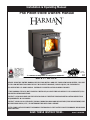
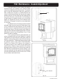
Harman P68 Installation & Operating Manual
- Catégorie
- Poêles
- Taper
- Installation & Operating Manual

R1
P68 Pellet Stove Owners Manual
SAVE THESE INSTRUCTIONS.
Installation & Operating Manual
R7
“Ce manuel est disponible en Français sur demande”
SAFETY NOTICE
PLEASE READ THIS ENTIRE MANUAL BEFORE YOU INSTALL AND USE YOUR NEW ROOM HEATER. FAILURE
TO FOLLOW INSTRUCTIONS MAY RESULT IN PROPERTY DAMAGE, BODILY INJURY, OR EVEN DEATH.
FOR USE IN THE U.S. AND CANADA. SUITABLE FOR INSTALLATION IN MOBILE HOMES.
IF THIS HARMAN STOVE IS NOT PROPERLY
INSTALLED, A HOUSE FIRE MAY RESULT. FOR YOUR SAFETY, FOL-
LOW INSTALLATION DIRECTIONS.
CONTACT LOCAL BUILDING OR FIRE OFFICIALS ABOUT RESTRICTIONS AND INSTALLATION INSPECTION
REQUIREMENTS IN YOUR AREA.
CONTACT YOUR LOCAL AUTHORITY (SUCH AS MUNICIPAL BUILDING DEPARTMENT, FIRE DEPARTMENT, FIRE
PREVENTION BUREAU, ETC.) TO DETERMINE THE NEED FOR A PERMIT.
CETTE GUIDE D'UTILISATION EST DISPONIBLE EN FRANCAIS. CHEZ VOTRE CONCESSIONNAIRE DE HARMAN
HOME HEATING.
Item # 3-90-00688

2
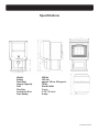
P68 Pellet Stove
Agence Américaine pour la Protection de l'Environnement
Ce modéle est dispensé par EPA certication d'aprés 40 CFR 60.531 par dènition [Appareil á bois (A) << Ratio air/combustible>>]
US ENVIRONMENTAL PROTECTION AGENCY
This model is exempt from EPA certication under 40 CFR 60.531 by denition [Wood Heater (A) "Air-to-Fuel Ratio"]
Harman P68 Pellet Stove
Label measures: 4-3/8" high X 10-3/4"wide
"PREVENT HOUSE FIRES"
Install and use only in accordance with manufacturer's installation and operation
instructions. Contact local building or re ofcials about restrictions and inspec-
tion in your area.
WARNING FOR MANUFACTURED HOMES: Do not install appliance in a sleeping
room. An outside combustion air inlet must be provided. The structural integrity of
the manufactured home oor, ceiling and walls must be maintained.
Refer to manufacturer's instructions and local codes for precautions required for
passing chimney through a combustible wall or ceiling. Inspect and clean exhaust
venting system frequently in accordance with manufacturer's instructions.
Use a 3" or 4" diameter type "L" or "PL" venting system.
Do not connect this unit to a chimney ue servicing another appliance.
FOR USE WITH PELLETIZED WOOD FUEL ONLY
Input Rating Max: 8 lb. fuel/hr.
U.S. Electrical Rating: 115 VAC, 60 Hz, Start 4.1 AMPS, Run 1.1 AMPS
European Electrical Rating: 240 VAC, 60 Hz, Start 2.0 AMPS, Run 1.1 AMPS
Route power cord away from unit.
DANGER: Risk of electrical shock. Disconnect power supply before servicing.
For further instruction, refer to owner's manual.
Replace glass only with 5mm ceramic available from your dealer.
Keep viewing and ash removal doors tightly closed during operation.
MODEL: "P68"
Room Heater Pellet Fuel Burning
Also for use in Mobile Homes.
This pellet burning appliance has been tested and
listed for use in Manufactured Homes in accordance
with OAR 814-23-900 through 814-23-909
Report #/ Raport # 135-S-13-2
Tested to / Testé à:
ASTM E1509, ULC-S627-00,
and ULC-C1482-M1990
WITHOUT
SIDE SHIELDS
WITH
SIDE SHIELDS
Ser# -
DO NOT REMOVE THIS LABEL / NE PAS ENLEVER CETTE ÉTIQUETTE
MADE IN USA / Fabriqué aux É.-U.
Modéle: "P68"
Appareil de chauffage à granulés de bois Utilisable dans des
mobile homes. Cet appareil de chauffage à granulés a été essayé
et homologué pour les maisons préfabriquées, conformément aux
normes 814-23-900 à 814-23-909 de l'OAR.
P.N. 3-90-06806
BAR CODE LABEL
MINIMUM CLEARANCES
TO COMBUSTIBLES:
Back Wall To Appliance 2" 2"
Side Wall To Appliance 20" 12"
Corner Installation
Walls To Appliance 13" 9"
FLOOR PROTECTION
Sides 2" / 5 cm
Back 0" / 0 cm
Front 6" / 15 cm
Use a non-combustible oor protector extending
under the unit and to the sides, front, and back of unit
as shown in Floor Protection Diagram. Measure front
distance from the surface of the glass door.
Recommended: Non-combustible oor protection
extending beneath any horizontal sections of
venting, including the "T" on the back when vent-
ing vertically.
"PREVENTION DES INCENDIES"
Respecter scrupuleusement les instructions du constructeur pour l'installation et les
consignes de fonctionnement. Respecter les règles de sécuritè en vigueur dans votre
région.
AVERTISSEMENT POUR MOBILE HOMES: Ne pas installer dans une chambre. ll est
imperatif de prévoir une prise d'alr extérieur. L'intégrité structurale du plancher, du plafond
et des murs doit étre strictement préservée.
Se reporter aux instructions du fabricant et aux réglementations spéciques locales
concernant les précautions requises lors de la traversée d'un mur ou d'un plafond.
Contróler et nettoyer fréquemment tout le systeme d'evacuation des fumées conformé-
ment aux recommandations du constructeur. Utiliser des tuyaux <<Spécial granulés>>
de Ø76 mm ou 102 mm. Ne pas raccorder ce poéle à un conduit de cheminée déjà
utilisé pour un autre appareil.
FONCTIONNE EXCLUSIVEMENT AVEC DES GRANULES DE BOIS.
ASTM E1509-ULC-C1482-M1990
Appareil de chauffage à granulé type (UM) 84-HUD. Consommation maximum: 3.63 kg/h.
U.S. Electrical Rating: 115 VAC, 60 Hz, Start 4.1 AMPS, Run 1.1 AMPS
Caractéristiques électriques: 240 VAC, 60 Hz-Intensité au démarrage 2.0A -Intensité
fonctionnement normal 1.1A. Tenir le cordon d'alimentation à l'écart du poèle.
DANGER: Risque d'électrocution. Débrancher l'appareil avant toute intervention.
Ne remplacer la vitre qu'avec une vitre céramique 5mm de méme qualité disponible
auprès de votre revendeur.
Pour une information plus compléte, se reporter à la notice d'utilisation. Tenir la porte
hermétiquement close durant fonctionnement.
2"-5cm
WITHOUT SIDE SHIELDS
20"-
51cm
Sans Écrans Latéraux
Tests réalisés par OMNI
TEST LABORATORIES, Inc.
Report № 135-S-13-2
DISTANCES MINIMALES DE
SECURITE:
Sans Avec
Écrans Écrans
Latéraux Latéraux
Mur arriére - Poéle 5cm 5cm
Mur lntéral - Poéle 51cm 30.5cm
Installation en angle
Mur- Angle Poéle diagonale 33cm 23cm
PROTECTION DE SOL
Côtés 5 cm
Derriére 0 cm
Devant 15 cm
Utiliser une protection de sol lncombustible dépas-
sant de l'appareil sur les côtés, l'arrière et le devant
comme indiqué sur le schéma. La mesure doit étre
prise á partir de la vitre frontale. ll est recommandé
que la protection de sol s'entende au dessous du
tuyau de fumée dans le cas d'une sortie horizontale
directe.
Date of Manufacture / Date de fabrication:
2008 2009 2010 JAN FEB MAR APR MAY JUN JUL AUG SEP OCT NOV DEC
Fabriqué par: Harman Home Heating 352 Mountain House Road, Halifax PA 17032
IGN
Portland
Oregon USA
Tested and
Listed By
OMNI-Test Laboratories, Inc.
2" -
5cm
6" - 15cm
0"
PROTECTION DE SOL
FLOOR PROTECTION
25" Wide x 33" Deep
63.5cm Wide x 84cm Deep
2" -
5cm
WITHOUT SIDE SHIELDS
13"
13"
3"min
3"min
33cm
33cm
8cm min
8cm min
Sans Écrans Latéraux

3
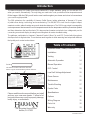
P68 Pellet Stove
Please read this entire manual before you install
and use your new room heater. Failure to fol-
low instructions may result in property damage,
bodily injury, or even death.
352 Mountain House Road
Halifax, PA 17032
Important Notes / Safety Concerns 4
Installation 5
Venting 7
Automatic Operation 14
Manual Operation 17
ESP Control 19
Low Draft Voltage Adjustment 20
Room Sensor 21
Maintenance 22
Trouble Shooting 27
Feeder Parts 28
Specications 29
Options 30
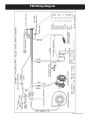
Wiring Diagram 31
Parts List 32
Warranty 33
Table of Contents
Introduction
This label is located on the back of the unit.
Please copy the Serial Number for future reference.
Serial #:
The Award-Winning P68 Pellet Stove has the widest BTU range available, giving you 0 to 68,000 BTU
when you need it, automatically. The only thing you need to do is set your desired room temperature and
llthehopper.WiththeP68youwillnoticeevenheatthroughoutyourhomeandalevelofconvenience
you never thought possible.
The P68 epitomizes the capability of Harman Pellet Stoves, taking advantage of Harman’s 20 years
of pellet stove design, technology and manufacturing. This 68,000 BTU stove has the highest output,
smartest controls, widest heating range, and minimal maintenance. The P68’s huge output is managed by
amicroprocessorthatsensestheroomtemperatureandtheretemperaturewithtinythermisterprobes
and then determines the best feed rate. This improved and smarter control also has a diagnostic port for
connecting an external display showing live working data for easier troubleshooting.
The platinum combination is Harman’s Patented Feeder & Burn Pot, and ESP Control which have been
developed to their highest state. These features work together to allow amazing heat output with different
fuel quality, ash content and moisture.
Agence Américaine pour la Protection de l'Environnement
Ce modéle est dispensé par EPA certication d'aprés 40 CFR 60.531 par dènition [Appareil á bois (A) << Ratio air/combustible>>]
US ENVIRONMENTAL PROTECTION AGENCY
This model is exempt from EPA certication under 40 CFR 60.531 by denition [Wood Heater (A) "Air-to-Fuel Ratio"]
Harman P68 Pellet Stove
Label measures: 4-3/8" high X 10-3/4"wide
"PREVENT HOUSE FIRES"
Install and use only in accordance with manufacturer's installation and operation
instructions. Contact local building or re ofcials about restrictions and inspec-
tion in your area.
WARNING FOR MANUFACTURED HOMES: Do not install appliance in a sleeping
room. An outside combustion air inlet must be provided. The structural integrity of
the manufactured home oor, ceiling and walls must be maintained.
Refer to manufacturer's instructions and local codes for precautions required for
passing chimney through a combustible wall or ceiling. Inspect and clean exhaust
venting system frequently in accordance with manufacturer's instructions.
Use a 3" or 4" diameter type "L" or "PL" venting system.
Do not connect this unit to a chimney ue servicing another appliance.
FOR USE WITH PELLETIZED WOOD FUEL ONLY
Input Rating Max: 8 lb. fuel/hr.
U.S. Electrical Rating: 115 VAC, 60 Hz, Start 4.1 AMPS, Run 1.1 AMPS
European Electrical Rating: 240 VAC, 60 Hz, Start 2.0 AMPS, Run 1.1 AMPS
Route power cord away from unit.
DANGER: Risk of electrical shock. Disconnect power supply before servicing.
For further instruction, refer to owner's manual.
Replace glass only with 5mm ceramic available from your dealer.
Keep viewing and ash removal doors tightly closed during operation.
MODEL: "P68"
Room Heater Pellet Fuel Burning
Also for use in Mobile Homes.
This pellet burning appliance has been tested and
listed for use in Manufactured Homes in accordance
with OAR 814-23-900 through 814-23-909
Report #/ Raport # 135-S-13-2
Tested to / Testé à:
ASTM E1509, ULC-S627-00,
and ULC-C1482-M1990
WITHOUT
SIDE SHIELDS
WITH
SIDE SHIELDS
Ser# -
DO NOT REMOVE THIS LABEL / NE PAS ENLEVER CETTE ÉTIQUETTE
MADE IN USA / Fabriqué aux É.-U.
Modéle: "P68"
Appareil de chauffage à granulés de bois Utilisable dans des
mobile homes. Cet appareil de chauffage à granulés a été essayé
et homologué pour les maisons préfabriquées, conformément aux
normes 814-23-900 à 814-23-909 de l'OAR.
P.N. 3-90-06806
BAR CODE LABEL
MINIMUM CLEARANCES
TO COMBUSTIBLES:
Back Wall To Appliance 2" 2"
Side Wall To Appliance 20" 12"
Corner Installation
Walls To Appliance 13" 9"
FLOOR PROTECTION
Sides 2" / 5 cm
Back 0" / 0 cm
Front 6" / 15 cm
Use a non-combustible oor protector extending
under the unit and to the sides, front, and back of unit
as shown in Floor Protection Diagram. Measure front
distance from the surface of the glass door.
Recommended: Non-combustible oor protection
extending beneath any horizo ntal section s of
venting, including the "T" on the back when vent-
ing vertically.
"PREVENTION DES INCENDIES"
Respecter scrupuleusement les instructions du constructeur pour l'installation et les
consignes de fonctionnement. Respecter les règles de sécuritè en vigueur dans votre
région.
AVERTISSEMENT POUR MOBILE HOMES: Ne pas installer dans une chambre. ll est
imperatif de prévoir une prise d'alr extérieur. L'intégrité structurale du plancher, du plafond
et des murs doit étre strictement préservée.
Se reporter aux instructions du fabricant et aux réglementations spéciques locales
concernant les précautions requises lors de la traversée d'un mur ou d'un plafond.
Contróler et nettoyer fréquemment tout le systeme d'evacuation des fumées conformé-
ment aux recommandations du constructeur. Utiliser des tuyaux <<Spécial granulés>>
de Ø76 mm ou 102 mm. Ne pas raccorder ce poéle à un conduit de cheminée déjà
utilisé pour un autre appareil.
FONCTIONNE EXCLUSIVEMENT AVEC DES GRANULES DE BOIS.
ASTM E1509-ULC-C1482-M1990
Appareil de chauffage à granulé type (UM) 84-HUD. Consommation maximum: 3.63 kg/h.
U.S. Electrical Rating: 115 VAC, 60 Hz, Start 4.1 AMPS, Run 1.1 AMPS
Caractéristiques électriques: 240 VAC, 60 Hz-Intensité au démarrage 2.0A -Intensité
fonctionnement normal 1.1A. Tenir le cordon d'alimentation à l'écart du poèle.
DANGER: Risque d'électrocution. Débrancher l'appareil avant toute intervention.
Ne remplacer la vitre qu'avec une vitre céramique 5mm de méme qualité disponible
auprès de votre revendeur.
Pour une information plus compléte, se reporter à la notice d'utilisation. Tenir la porte
hermétiquement close durant fonctionnement.
2"-5cm
WITHOUT SIDE SHIELDS
20"-
51cm
Sans Écrans Latéraux
Tests réalisés par OMNI
TEST LABORATORIES, Inc.
Report № 135-S-13-2
DISTANCES MINIMALES DE
SECURITE:
Sans Avec
Écrans Écrans
Latéraux Latéraux
Mur arriére - Poéle 5cm 5cm
Mur lntéral - Poéle 51cm 30.5cm
Installation en angle
Mur- Angle Poéle diagonale 33cm 23cm
PROTECTION DE SOL
Côtés 5 cm
Derriére 0 cm
Devant 15 cm
Utiliser une protection de sol lncombustible dépas-
sant de l'appareil sur les côtés, l'arrière et le devant
comme indiqué sur le schéma. La mesure doit étre
prise á partir de la vitre frontale. ll est recommandé
que la protection de sol s'entende au dessous du
tuyau de fumée dans le cas d'une sortie horizontale
directe.
Date of Manufacture / Date de fabrication:
2008 2009 2010 JAN FEB MAR APR MAY JUN JUL AUG SEP OCT NOV DEC
Fabriqué par: Harman Home Heating 352 Mountain House Road, Halifax PA 17032
IGN
Portland
Oregon USA
Tested and
Listed By
OMNI-Test Laboratories, Inc.
2" -
5cm
6" - 15cm
0"
PROTECTION DE SOL
FLOOR PROTECTION
25" Wide x 33" Deep
63.5cm Wide x 84cm Deep
2" -
5cm
WITHOUT SIDE SHIELDS
13"
13"
3"min
3"min
33cm
33cm
8cm min
8cm min
Sans Écrans Latéraux

4
P68 Pellet Stove
DO NOT INSTALL A FLUE DAMPER IN THE
EXHAUST VENTING SYSTEM OF THIS
UNIT.
DO NOT CONNECT THIS UNIT TO A
CHIMNEY FLUE SERVING ANOTHER
APPLIANCE.
Mobile home installation should be done
in accordance with the Manufactured
Home and Safety Standard (HUD), CFR
3280, Part 24.
CAUTION
THE STRUCTURAL INTEGRITY OF THE
MOBILE HOME FLOOR, WALL, AND
CEILING/ROOF MUST BE MAINTAINED.
CAUTION
KEEP COMBUSTIBLE MATERIALS
(SUCH AS GRASS, LEAVES, ETC.) AT LEAST
3 FEET AWAY FROM THE FLUE OUTLET ON
THE OUTSIDE OF THE BUILDING.
IMPORTANT NOTES
Installation and repair of this Harman stove
should be done by a qualied service person.
We recommend that the stove be inspected
before use and at least annually by a qualied
service person. Periodic cleaning is required
throughout the heating season and at the end
of each winter for the stove to work efciently.
See cleaning instructions on page 22.
Mobile/Manufactured Home Standards
Do Not Allow Installation In Rooms
Designated For Sleeping.
WARNING

5
P68 Pellet Stove
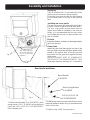
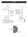
Assembly and Installation
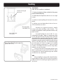
Unpacking
The P68 is bolted (1/4 x 1" hex head bolts) to the
skid to prevent movement during shipping.
To free the stove from the skid you must remove
the hold-down bolts in the rear of the pedestal
base.
Installing rear cover panels
The rear cover panels are removed from the stove
to make it easier to get at the hold-down bolts.
The rear cover panels are packed inside the
hopper and should be installed on the stove as
shown. It is recommended that the rear covers
are installed after the unit is in place and the vent
pipe is installed.
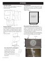
Firebrick
Installtherebrickverticallyontheanglebracket
above the burnpot.
Flame Guide
Install the cast iron ame guide on top of the
burnpot.Makesurethattheameguideisfully
seated on the vertical sides of the burn pot and
that the back of the guide rests against the body
of the stove.
INSTALL EXHAUST VENT AT CLEARANCES
SPECIFIED BY THE MANUFACTURER. Most
pellet pipes require a minimum of 3" of clearance
Rear Cover
Panels
Shipping Bolts
Note: These same holes
are used for securing the
stove in mobile home
installation.
8mm Spring Washer
3-31-08558
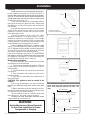
1. Remove wood handle ( P.N. 4-30-00123 ), 6mm
spring washer ( P.N. 3-31-08558 ) and socket head
cap screw ¼-20 x 2-1/4" ( P.N. 3-30-3025202252 )
from hardware pack.
Wood Handle
3-40-00123
SHCS 1/4-20 x 2-1/4
3-30-3025202252
Door Handle Installation
2. Install spring washer and wood handle onto socket
headcapscrewasshowning.2andthreadonto
latch on front door.
3. Tighten using a 3/16" hex key wrench.
Fig. 2
Fig. 1

6
P68 Pellet Stove
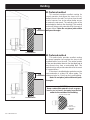
Installing
Placethestoveonanoncombustibleoorprotec-
tor that extends a minimum of 6 inches to the front, 2
inchestothesidesandushwiththerearofthehopper.
SeeFig.6.Theminimumoorprotectormaterialis20
gaugesheetmetal.Otheroorprotectormaterialsare
ceramic tile, stone, brick, etc.
Place the stove away from combustible walls at
least as far as shown in Figures 3,4 and 5. Please note
the difference in side wall clearance with and without
side shields.
Note that the clearances shown are minimum for
safety but do not leave much room for access when
cleaning or servicing. Please take this into account
when placing the stove.
Connect the power cord to a 120 V.A.C. 60Hz
grounded receptacle. (A surge protector is recom-
mended to protect the circuit board.) If the voltage
entering your home is below 116 volts your stove may
not work properly. Also be sure that the polarity of the
outlet that the stove is plugged into is correct.
Priorto installing theuepipe, connect a draft
meter. (The draft meter must have a minimum range
of0-.5.)Recordtherstreading.Connectuepipeto
stove and be sure all doors and windows in the home
are closed. Record the second draft reading_______.
If the second reading is more than .05" lower than the
rstreading,checkforpossiblerestrictionsortheneed
for outside air (see page 9). For more information on
the draft test procedure, refer to Page 20.
Mobile Home Installation
When installing this unit in a mobile home several
requirements must be followed:
1.Theunitmustbeboltedtotheoor.Thiscan
be done with 1/4" lag screws through the 2 holes in
the base plate.
2. The unit must also be connected to outside air.
See page 9.
3. Floor protection and clearances must be fol-
lowed as shown.
4. Unit must be grounded to the metal frame of
the mobile home.
CAUTION: This appliance must be vented to the
outside.
Due to high temperatures, the stove should be
placedoutoftrafcandawayfromfurnitureanddrap-
eries.
Children and adults should be alerted to the haz-
ards of high surface temperatures and should stay away
to avoid burns to skin and/or clothing.
Young children should be carefully supervised
when they are in the same room as the stove.
Clothing and other ammable materials should
not be placed on or near this unit.
Installation
9"-13"
9"-13"
9" With Side Shields
13" Without Side Shields
Floor Protection must be 2 inches to each side, 6
inches to the front, and 0 inches to the back of the
stove. Floor Protector minimum: 25" wide x 33"
deep.
Fig. 3
Fig. 4
Fig. 6
2"
6" (measured
from glass)
0"
(even with
hopper)
Fig. 5
20"
2"
25" minimum
2"
33" minimum
Mobile/Manufactured Home Standards
Do Not Allow Installation In Rooms
Designated For Sleeping.
WARNING

7
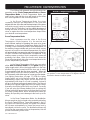
P68 Pellet Stove
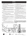
Venting
Requirements for Terminating the Venting
WARNING: Venting terminals must not be re-
cessed into a wall or siding.
NOTE: Only PL vent pipe wall pass-throughs
andrestopsshouldbeusedwhenventingthrough
combustible materials.
NOTE: Always take into consideration the effects
of the prevailing wind direction or other wind currents
thatmaycauseyashand/orsmokewhenplacingthe
termination vent.
In addition, the following must be observed:
A. The clearance above grade must be a mini-
mum of 18".
1
B. The clearance to a window or door that may
be opened must be a minimum of 48" to the side, 48"
below the window/door, and 12" above the window/
door.
1
( with outside air installed, 18” )
C. A 12" clearance to a permanently closed
window is recommended to prevent condensation
on the window.
D. The vertical clearance to a ventilated soft
located above the terminal within a horizontal distance
of 2 feet (60 cm) from the center-line of the terminal
must be a minimum of 18".
E.Theclearancetoanunventilatedsoftmust
be a minimum of 12".
F. The clearance to an outside corner is 11" from
center of pipe.
G. The clearance to an inside corner is 12".
H. A vent must not be installed within 3 feet (90
cm) above a gas meter/regulator assembly when
measured from the horizontal center-line of the regu-
lator.
1
I. The clearance to service regulator vent outlet
must be a minimum of 6 feet.
1
J. The clearance to a non-mechanical air supply
inlet to the building or the combustion air inlet to any
other appliance must be a minimum of 48”.
1
K. The clearance to a mechanical air supply inlet
must be a minimum of 10 feet.
1
(with outside air installed, 6 feet )
L. The clearance above a paved sidewalk or a
paved driveway located on public property must be a
minimum of 7 feet.
1,2
M. The clearance under a veranda, porch, deck
or balcony must be a minimum of 12 inches.
1,3
NOTE: The clearance to vegetation and other
exterior combustibles such as mulch is 36” as mea-
sured from the center of the outlet or cap. This 36”
radius continues to grade or a minimum of 7 feet
below the outlet.
1
Certain Canadian and or Local codes or regula-
tions may require different clearances.
2
A vent shall not terminate directly above a side-
walk or paved driveway which is located between two
single family dwellings and serves both dwellings.
3
Only permitted if veranda, porch, deck, or bal-
cony is fully open on a minimum of 2 sides beneath
theoor.
NOTE: Where passage through a wall, or partition
of combustible construction is desired, the
installation shall conform to CAN/CSA-B365. (if
in Canada)
= Vent terminal
V

8
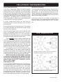
P68 Pellet Stove
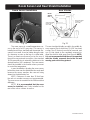
Venting
A combustion blower is used to extract the
combustiongasesfromtherebox.Thiscausesa
negativepressureinthereboxandapositivepres-
sure in the venting system as shown in Fig. 7. The
longer the vent pipe and more elbows used in the
system, the greater the ow resistance. Because
of these facts we recommend using as few elbows
as possible and 15 feet or less of vent pipe. The
maximum horizontal run should not exceed 48".
If more than 15 feet of pipe is needed, the interior
diameter should be increased from 3" to 4" because
alargerpipecauseslessowresistance.Be sure
to use approved pellet vent pipe wall and ceiling
pass-through ttings to go through combustible
walls and ceilings. The use of a starting collar is
notalwaysnecessary.Therstpieceofpipeshould
be fastened securely with at least 2 fasteners to the
uecollarofthestove.Ifastartingcollarisusedto
attach the venting system to the stove, the starting
collar must be sealed to the stove with high temp
silicone caulking.
Vent Pipe
Pellet venting pipe (known as L or PL vent)
is constructed of two layers with air space between
the layers. This air space acts as an insulator and
reduces the outside surface temperature to allow
a clearance to combustibles of 1 to 3 inches. The
sections of pipe lock together to form an air tight
seal in most cases. However, in some cases a
perfect seal is not achieved. For this reason and
the fact that the P68 operates with a positive vent
pressure we specify that the joints also be sealed
with silicone. Aluminum tape can also be used for
any joint that is 1ft. or more from the outlet of the
stove.
We cannot emphasize enough, the
importance of sealing every seam and joint in the
venting system which is inside the home. Even the
smallest pin hole can leak and when it does you will
smell wood smoke or a creosote smell in the room.
If this occurs check for leaks. Leaks are easiest
to see during start-up. Alternatively you can use a
smoke pellet to leak test the venting before lighting
yourrstre.
Venting
IMPORTANT NOTICE
Approved Pellet Vent Pipe Such As, Type "L"
Or "PL", Must Be Used.
= Positive Static Pressure
= Negative Static Pressure
+
+
-
+
-
Fig. 7

9
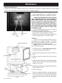
P68 Pellet Stove
Outside air ex pipe
goes here.
Inlet Cover part#
1-10-08542
Flex pipe part#
1-00-08543 (25')
Outside Air
Here arefourbenetsof outside air:
1. Having air introduced from outside the living area
boostsoverallefciency.
2. It eliminates draft problems that can occur in tight
homes.
3. It reduces smoke spillage in the event of a power
failure.
4. It allows your vent termination to be as close as
18" from windows or doors.
Outside air is optional except in mobile
homes and where building codes require. The
benetofoutsideairismainlynoticedinsmall,very
tight, houses.
To install outside air use 2 3/8" I.D. non-
combustibleexpipe.Thereisabreak-awayhole
on the rear panel of the P68 stove which must be
removedbeforeconnectingtheexpipe.The pipe
should be run outside and terminate to the side or
belowtheventpipeoutletsotheueoutletismore
than 12" from the inlet cover. The maximum length
run of this pipe is 15 feet. If a longer run is needed
the size must be increased to 3". Inlet cover part
number 1-10-08542 should be used to keep birds,
rodents, etc.out of the pipe.
You may choose to use the optional Direct Vent
Wall Passthrough Kit (part #1-00-677077) which
incorporates the venting passthrough and outside
air inlet into one component.
HRV
When installing in a house with a Heat Reclaim-
ing Ventilation System (HRV) be sure the system is
balanced and is not creating a negative pressure in
the house.
Venting
Direct Vent Wall Passthrough Kit
(part #1-00-677077)

10
P68 Pellet Stove
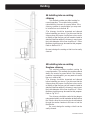
#2 Preferred method
This method also provides excellent venting
for normal operation but requires the stove to be
installed farther from the wall. The vertical portion
oftheventshouldbethreetovefeethighandat
least three inches from a combustible wall. This
vertical section will provide natural draft in the event
of a power failure.
If the stove is installed below grade be sure the
vent termination is at least 18" above grade. The
outlet must also be 1 foot from the house/building.
Note: Do not place joints within wall pass-
throughs.
CAUTION
Keep combustible materials (such as grass,
leaves, etc.) at least 3 feet away from the ue
outlet on the outside of the building.
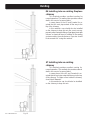
#1 Preferred method
This method provides excellent venting for
normal operation and allows the stove to be in-
stalled closest to the wall. Two inches from the wall
is safe; however, four inches allows better access
to remove the rear panel. The vertical portion of the
ventshouldbethreetovefeethigh.Thisvertical
section will help provide natural draft in the event of
a power failure.
Note: Do not place joints within
wall pass-throughs.
Venting
Fig. 8
3 ft.
to combustibles
Fig. 9
3 ft.
to combustibles
3 ft.
to combustibles
36" min
clearance to any
combustible
material
12" min. wall to outlet
3 ft.
to combustibles

11
P68 Pellet Stove
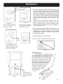
#4 Installing into an existing
chimney
This method provides excellent venting for
normal operation. This method also provides
natural draft in the event of a power failure. If the
chimney condition is questionable* you may want
to install a liner as in method #7.
*The chimney should be inspected and cleaned
before installing your stove. If you discover that the
chimney does not have a clay tile liner or has cracks
orakingofthetilelineryouwillneedtoinstalla
stainless steel liner within the chimney. In most cases
the inside diameter of this liner should be 4". Either
exibleorrigidlinermaybeusedforthispurpose.
Refer to Method 6 & 7.
Be sure to design the venting so that it can be easily
cleaned.
#5 Installing into an existing
replace chimney
This method provides excellent venting for
normal operation. This method also provides natural
draft in the event of a power failure. If the chimney
condition is questionable* you may want to install a
liner as in method #6.
*The chimney should be inspected and cleaned
before installing your stove. If you discover that the
chimney does not have a clay tile liner or has cracks
orakingofthetilelineryouwillneedtoinstalla
stainless steel liner within the chimney. In most cases
the inside diameter of this liner should be 4". Either
exibleorrigidlinermaybeusedforthispurpose.
Refer to Fig. 6 & 7.
The chimney should be sealed at the damper
usingasteelplate,orwithinsulationattherstue
tile. In both cases the connector pipe should extend
through the smoke chamber to the base or into the
rstuetile.
Be sure to design the venting so that it can be
easily cleaned.
Fig. 10
Fig. 11
Venting

12
P68 Pellet Stove
#6 Installing into an existing replace
chimney
This method provides excellent venting for
normal operation. This method also provides natural
draft in the event of a power failure.
In some places in the US and Canada it is re-
quired that the vent pipe extend all the way to the
top of the chimney.
In this method a cap should also be installed
on the chimney to keep out rain. Be sure to use ap-
provedpelletventpipettings.Sealpipejointswith
silicone or aluminum tape in addition to the sealing
system used by the manufacturer. Pipe size should
be increased to 4" using this method.
#7 Installing into an existing
chimney
This method provides excellent venting for
normal operation. This method also provides natural
draft in the event of a power failure.
In some places in the US and Canada it is re-
quired that the vent pipe extend all the way to the top
of the chimney. The pipe or liner inside the chimney
should be 4"diameter.
In this method a cap should also be installed
on the chimney to keep out rain.
Fig. 12
Fig. 13
Venting

13
P68 Pellet Stove
#8 Installing through the ceiling
Through the ceiling vent, follow PLvent
manufacturers recommendations when using wall
and ceiling pass through. Note: Do not place joints
within wall pass-throughs.
Fig. 14
PL vent manufacturer's
firestop spacer and
support
(See Page 6 for
corner installation
clearances)
Minimum flue vent
conguration
It is recommended that outside
air be installed with this venting
congurationtoreducesmoke
and creosote smell in the room
in the event of power failure.
Min. above ground level
18"
Storm collar
Flashing
3" min.
3" min.
12" min.
3" min.
Venting
Fig. 15
3" min.
No insulation or
other combustible
materials are
allowed within
3" of the pellet
vent pipe. Unless
specified by the
pipe manufacturer
12" min. wall to outlet
36" min clearance to any
combustible material
Fig. 16

14
P68 Pellet Stove
P68 AUTOMATIC IGNITION/OPERATION
Room Temperature Mode: This setting, see above,
will produce a room temperature of 70 degrees with the
distribution blower at medium speed.
The P68 is a fully automatic stove that features two
operating modes;
Stove Temperature Mode and Room
Temperature Mode. In Stove Temperature Mode, you
select a burn rate and the stove will remain at the same
burn rate regardless of the room temperature.
In the Room Temperature Mode the stove
constantly monitors the temperature in the room and
adjuststhesizeofthereandtheheatoutputofthestove
so that the room is kept at a constant temperature. Room
mode, in the AUTO position, has the added advantage of
turning the stove off if no heat is required and turning the
stove on again when the room temperature drops below
your desired room temperature.
Room Temperature Mode
Most consumers use the stove in the Room
Temperature Mode because it is the easiest and
most efcient method of keeping the room at a given
temperature. In the Room Temperature Mode, the Room
Sensing Probe constantly monitors room temperature. As
the weather changes outside and your home needs varying
amounts of heat to be at a desired temperature, the stove
willautomaticallyincreasesizeandheatoutputofthere
so that a constant even temperature is maintained. If the
weather warms up and no heat is required the stove will
gradually shut down. When the house cools down the
stove will automatically bring the room temperature to the
precise temperature you desire.
In the Room Temperature Mode you can select
either Auto or Manual modes for the igniter using the
igniter toggle switch. When the toggle switch is in the Auto
position the igniter located inside the burn pot is ready
toautomaticallylighttherewhenrequired.Whenthe
toggle switch set to the Manual position the stove can
belitmanuallywitheitheragelorawaxtyperestarter.
(see lighting instructions on page 17.) With the igniter
toggle switch set in the Manual position the stove will
automatically adjust heat output, but the stove will not
automatically shut down if no heat is required. Instead it
will go to its lowest setting and remain there. The Manual
position on the igniter toggle switch lets you light the stove
manually, should the igniter fail for any reason. Secondly
if you are using the Harman battery back up system the
Manual setting will prevent the stove from turning off and
on during a power failure, which would drain the back up
battery, and possibly cause damage to the back-up or the
stove.
In the Room Temperature Mode, the distribution
blower speed can be increased or decreased by adjusting
the Room Temp/Off/Stove Temp dial between L and H.
As output of the stove increases, the speed of the blower
will increase automatically to insure that more heat is
transferred out into the room. The distribution blower will
shut off as the room reaches the set temperature, this will
prevent overheating of the room.
Room Temperature Mode

15
P68 Pellet Stove
Stove Temperature Mode
In the Stove Temperature Mode and with the igniter
toggle switch in the Auto position, the stove will light
automatically and can be adjusted to the desired setting
using the same temperature control dial as is used in
the Room Temperature Mode. The heat output and fuel
consumption will remain constant regardless of room
temperature. The settings from 1 to 7 on the inner ring
of the dial provide for relative heat output settings with
1 being low and 7 being the maximum.
In Stove Temperature Mode, the stove will not
automatically shut off unless the stove runs out of fuel
or is turned off.
Never pull the plug to shut down the stove. This will stop
the combustion blower and smoke will escape through
window and door gaskets.
When the igniter toggle switch is set to manual in this
mode, the distribution blower will not turn on with a
temperature dial setting from 1 to 5. The advantage of
this mode is to allow the operator to have a large viewing
rewithoutblowingextraheatintotheroom.
During manual operation, with the temperature dial
set at #5 or less, the distribution fan will not operate. A #5
on the temperature dial and a #5 on the feed adjuster is
approximately 80% output. It is not necessary to operate
the distribution blower below this point. Therefore, the
controlallowsahigherburnrate(alargerviewingre)
without an excess of hot air blowing into the room.
An example of when to use the Manual Stove
TemperatureModeisifyouwanttowatchalargere
and the room is already up to temperature. The Stove
TemperatureModeallowsyoutohavealargerreand
a lower sound level, without the distribution blower.
NOTE: During the use of this mode, if you keep
increasing the temperature dial setting to increase
the re size, the distribution blower will automati-
cally come on when the ESP Temperature reaches
350
o
F, or 81% output.
Feed Adjuster Knob
For most premium grade pellet fuels the Feed Adjuster
Knob should be set at 4. If higher ash fuels are used
the setting should be increased to 5 or 6. Also higher
settings are required if you would like to get the
maximum heat output from the stove. At the maximum
burn rate (with the temperature dial on 7/90° and the
feed adjuster at 6) there should be 1" or more of ash on
the front of the burn pot. If there is less than 1" of ash,
turn the feed adjuster knob down to a lower setting.
P68 AUTOMATIC IGNITION/OPERATION
Shut Down Procedure
The best way to shut down the stove is simply let it run
out of pellets. The stove will shut down automatically.
Alternatively, you can turn the Mode Selector to “off”.
Thiswillcausetheretograduallydiedownandgoout.
Therewillnotgooutimmediatelyandmaytakemore
than an hour to fully shut down.
If the stove is left to run out of fuel, you may get a 6
blink status light. If this happens simply reset the control
board by turning the mode selector to OFF and back
ON.
The setting above will produce continuous maximum heat
output with the distribution blower at full speed.
Stove Temperature Mode
The setting above will produce continuous medium heat
output with the distribution blower at low speed.

16
P68 Pellet Stove
NOTICE:
Be Sure there is no fuel or other combustibles
in the ash pan prior to lighting.
Igniter Switch to"AUTO"(up position)
Make sure the unit is plugged into a 120 VAC, 60
HZ electrical source. The power light should be the
only light lit.
1.
Turn Mode Selector to "OFF".
2. Fill hopper with pellets.
1
3. Clean burn pot with scraper, if necessary.
5
4. If starting after an empty hopper, turn Feed
Adjuster to "TEST" (for one 60 second cycle).
2
This will purge pellets into the auger tube and also
allow you to check the motors for operation.
NOTE: The auger motor will not operate with
the view door or ash pan door open.
3
5. Turn Feed Adjuster to #4.
4
6. Flip the Igniter Switch up into the "AUTO"
position.
7. Turn the Temperature Dial to desired room
temperature.
8. Turn Mode Selector to Room Temperature or
Stove Temperature.
9. Fill hopper with pellets and remove ashes as
required.
6
P68 AUTOMATIC START UP
Helpful Hints
1. Fines are small pieces of broken pellets (sawdust). Fines do not
ow easily and often build up on the hopper funnel bottom angles.
You can push these nes into the feeder opening and then ll the
hopper with pellets. As the system works, they will be burned. Or
you can clean them out before lling the hopper.
2. The "TEST" cycle will operate the feeder motor for exactly one
minute. Turning to "TEST" again and again may purge too much
fuel into the burn pot causing excessive smoke on start-up.
3. The rebox low pressure switch will not allow the auger motor
or the igniter element to operate if the view door or the ash pan
door are open.
4. Adjust Feed Rate. If this is your rst re or you are trying different
pellets, set the feed adjuster to #4, Fig. 17. This is a conservative
number and will probably need to be increased. After you know a
feed rate setting that works well, use that setting. Remember, if your
feed rate is too high you may waste fuel.
5. This is usually a weekly maintenance procedure. Cleaning the
burn pot with the scraper with a small amount of new fuel in the
bottom is not a problem. First, scrape the ashes on the front of the
burn pot into the ash pan. Then, scrape the top surface of the burn
pot downward into the base of the burn pot. When the stove is ignited
these scrapings will be pushed out by the feeder and burned.
6. The ash pan can hold the ashes from approximately 1 ton of
premium fuel. This means the ashes will only need to be emptied
a few times a year.
7. Setting the feed adjuster # for maximum burn: With the unit
burning in "AUTO", turn to "Stove Mode" and put the fan on "H".
Set the Temperature Dial to #7. Allow the unit to burn for about 30
minutes and check ash on front of burn pot. Fig. 18. If the ash line
is larger than 1", turn the feed adjuster from #4 to #5. Allow another
30 minutes of burn time and check again. If , at #6 setting, a 1" or
less ash bed is not obtainable, it is not a problem. The 1" ash bed
is only a maximum burn rate and at most normal settings the ash
bed will be larger.
Fig. 17
WARNING
"NEVER USE GASOLINE, GASOLINE-TYPE LANTERN
FUEL, KEROSENE, CHARCOAL LIGHTER FLUID, OR
SIMILAR LIQUIDS TO START OR "FRESHEN UP " A
FIRE IN THIS HEATER. KEEP ALL SUCH LIQUIDS
WELL AWAY FROM THE HEATER WHILE IN USE".
WARNING
ONLY USE WOOD PELLET FUEL. DO NOT BURN
GARBAGE IN STOVE.
SeeHint #7.
Fig. 18
1"
Flame Guide
Starting First Fire

17
P68 Pellet Stove
The P68 Pellet Stove is capable of manual operation. This also allows the opera-
tor to manually control operation during an emergency (i.e. igniter failure, when using
a 502H battery backup, as opposed to the 512H, or when using certain generators.)
The unit can be switched between "AUTO" and "MANUAL" at any time during
operation.
Igniter Switch to "MANUAL"
Room Temperature Mode
Therewillhavetobelitwithstartinggelanda
match, or started automatically, see "Automatic Opera-
tion" on Page 15. Turn to "Manual" position when the
reisestablished.
The difference between "AUTO" Room Tempera-
ture Mode and "Manual" Room Temperature Mode is
thattherewillnotgooutastheroomtemperature
goes above the control board setting. The unit can
only go to low burn and will remain there until it runs
out of fuel or until more heat is needed and the feed
rate increases. Feed rate adjustments and dial set-
tings are the same as "AUTO" settings.
The blower
will shut off completely if the temperature on the
ESP is too low.
Igniter Switch to "MANUAL"
Stove Temperature Mode
The advantage of this mode is to allow the opera-
tortohavealargeviewingrewithoutblowingextra
heat into the room.
During operation, with the temperature dial set at
#5 or less, the distribution fan will not operate. A #5 on
the temperature dial and a #5 on the feed adjuster is
approximately 80% output. It is not necessary to oper-
ate the distribution blower below this point. This control
settingallowsahigherburnrate(alargerviewingre)
without an excess of hot air blowing into the room.
An example of when to use the Manual Stove
TemperatureModeisifyouwanttowatchalargere
and the room is already up to temperature. The Stove
TemperatureModeallowsyoutohavealargerreand
a lower sound level, without the distribution blower.
NOTE: During the use of this mode, if you keep
increasing the temperature dial setting to increase
the re size, the distribution blower will automati-
cally come on when the ESP Temperature reaches
350
o
F, or 81% output.
NOTE: When starting the unit in the "AUTO"
mode and switching to "MANUAL", the re must be
large enough to start the distribution blower. The
starting of the blower is a signal that the start cycle
is completed and the re will not go out.
P68 MANUAL IGNITION/OPERATION
This setting will produce a large viewing re
without a distribution blower operating.
Manual Stove Temperature Mode
Room Temperature Mode: This
setting, see below, will produce a
room temperature of 70 degrees
with the distribution blower at
medium speed.

18
P68 Pellet Stove
P68 MANUAL START UP
Igniter Switch to"MANUAL"
(down position)
Make sure the unit is plugged into a 120
VAC, 60 HZ electrical source. The power light
should be the only light lit.
1. Turn FEED ADJUSTER to desired feed rate.
No. 4 is good for most pellets.
4
2. Turn the MODE SELECTOR to “OFF” and
then to the desired mode. This will reset con-
trol and start the combustion motor.
3. Turn the TEMPERATURE DIAL to the desired
setting.
4. Clean burn pot with scraper if necessary.
5
5. Fill burn pot with pellets, only level with front
edge. (Do Not Over Fill).
6. Add starting gel on top of the pellets. Stir gel
into pellets for fast lighting.
7. Light starting gel with a match, and close the
door. Operationwillbeginwhentherereaches
the proper temperature.
3
8. Fill hopper with pellets and remove ashes
as required.
1, 6
"NEVER USE GASOLINE, GASOLINE-TYPE LANTERN
FUEL, KEROSENE, CHARCOAL LIGHTER FLUID, OR
SIMILAR LIQUIDS TO START OR "FRESHEN UP " A
FIRE IN THIS HEATER. KEEP ALL SUCH LIQUIDS
WELL AWAY FROM THE HEATER WHILE IN USE".
WARNING
Helpful Hints
1. Fines are small pieces of broken pellets (sawdust). Fines do not
ow easily and often build up on the hopper funnel bottom angles.
You can push these nes into the feeder opening and then ll the
hopper with pellets. As the system works, they will be burned. Or
you can clean them out before lling the hopper.As the system
works, they will be burned.
2. The "TEST" cycle will operate the feeder motor for exactly one
minute. Turning to "TEST" again and again may purge too much
fuel into the burn pot causing excessive smoke on start-up.
3. The rebox low pressure switch will not allow the auger motor
or the igniter element to operate if the view door or the ash pan
door are open.
4. Adjust Feed Rate. If this is your rst re or you are trying different
pellets, set the feed adjuster to #4, Fig. 19. This is a conservative
number and will probably need to be increased. After you know a
feed rate setting that works well, use that setting. Remember, if your
feed rate is too high you may waste fuel.
5. This is usually a weekly maintenance procedure. Cleaning the
burn pot with the scraper with a small amount of new fuel in the
bottom is not a problem. First, scrape the ashes on the front of the
burn pot into the ash pan. Then, scrape the top surface of the burn
pot downward into the base of the burn pot. When the stove is ignited
these scrapings will be pushed out by the feeder and burned.
6. The ash pan can hold the ashes from approximately 1 ton of
premium fuel. This means the ashes will only need to be emptied
a few times a year.
7. Setting the feed adjuster # for maximum burn: With the unit
burning in "AUTO", turn to "Stove Mode" and put the fan on "H".
Set the Temperature Dial to #7. Allow the unit to burn for about 30
minutes and check ash on front of burn pot. Fig. 21. If the ash line
is larger than 1", turn the feed adjuster from #3 to #4. Allow another
30 minutes of burn time and check again. If , at #6 setting, a 1" or
less ash bed is not obtainable, it is not a problem. The 1" ash bed
is only a maximum burn rate and at most normal settings the ash
bed will be larger.
Fig. 20
Fig. 19
Fig. 21
1"
See Hint #7.
WARNING
ONLY USE WOOD PELLET FUEL. DO NOT BURN
GARBAGE IN STOVE.
Starting First Fire
NOTICE:
Be Sure there is no fuel or other combustibles
in the ash pan prior to lighting.

19
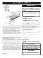
P68 Pellet Stove
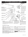
P68 AUTOMATIC IGNITION ESP CONTROL
Feed adjuster
Sets the maximum
feed rate
Test
Runs all motors at full
speed for one minute to
check operation. After
two minutes the stove
will go to minimum burn
and the blowers will
alternate from high to
low every minute to
remind you that you are
still in "Test Mode".
Igniter switch
Set to appropriate
Start-Up mode.
Distribution Blower
speed adjustment
range.
L = low
H = high
V a r i a b l e s p e e d
anywhere between L
and H; although as the
stove temp. goes up ,
so does the low end of
the scale.
Temp dial
Allows you to adjust the room temperature in Room
Temp Mode using the outer scale marked in degrees
Fahrenheit. It also allows you to adjust the stove
temperature while in Stove Temp Mode using the inner
scale marked from 1 to 7.
Mode Selector
Allows you to choose between
Room Temp Mode, Stove Temp
Mode, or OFF. Also allows you
to vary the distribution blower
speed by turning the knob to
the high or low side of each
mode.
Power Light
Indicates power to the
control.
Indicates power to the
feed motor.
Indicates power to the
igniter
Indicates power to
combustion blower
Status Light
Will be lit in either stove
or room temp mode
when pointer is not
within off position band
except after normal shut
down. Blinks to indicate
errors listed below.
Indicates power to
distribution blower.
Status light error messages:
1 Blink: Indicates control board self diagnostic fail-
ure. This requires a manual reset*.
3 Blinks: Indicates ESP (Exhaust Sensing Probe)
failure. This requires a manual reset*.
4 Blinks: Can occur only in Room Temp Mode and
indicates Room Sensing Probe failed or not installed.
If a Room Sensing Probe is then installed, the status
light will automatically reset.
5 Blinks (In Igniter Auto. Mode Only): Indicates
that the unit has failed to light within the 36 minute
start cycle. To reset - Turn Mode Selector to "OFF",
then turn to either mode again.
6 Blinks : Indicates that the control has calculated
poor or incomplete combustion occurring for more
than 50 minutes.
A six blink status may be set if the stove is allowed
to run out of pellets. To reset, turn mode selector to
"OFF" then back on to the desired mode. If the unit
was not out of pellets, see Troubleshooting section,
Page 27, for more details.
* Manual reset- disconnect power cord for a few
seconds and reconnect. If error still occurs call your
Dealer.
Dealer Diagnostic Port
For dealer maintenance
only. Requires special DDM
monitor supplied to Harman
Dealers exclusively.

20
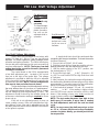
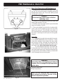
P68 Pellet Stove
These units are pre-tested at the factory with
exactly 120 Volts A.C., 60 Hz. They are checked and
adjustedforreboxtightness,gasketleakage,motor
operation and igniter operation. The P68 is then factory
set at a mid-point adjustment and in most cases will not
need any adjustments.
NOTE: The factory low draft
setting may not be correct for the unit's permanent
installation conditions.
The control board on the P68 is equipped with
a low draft adjustment port. Located on the control
face just to the right of the igniter light. This voltage
adjustment is provided to allow the unit to be adjusted
for the household voltage where the unit is going to be
in permanent operation.
NOTE: The line voltage varies
from area to area and often home to home.
The low draft voltage should be adjusted to achieve
themostefcientburnonlowburnor"maintenance".
This voltage adjustment allows the installer to change
the low voltage set point approximately 10 volts. This
adjustment should be done by the installer during set
up because a draft meter reading is required to insure
proper set up.
If the unit is not adjusted properly, it does not
cause a safety concern. If the unit is adjusted too high,
onlyefencyislost.Iftheunitisadjustedtoolow,the
low draft pressure switch will not allow the feed motor
or the igniter to operate.
Co mb us tion
Motor Speed
Control
Low draft only
set point.
The small straight
screwdriver slot is
plastic; therefore,
the unit can be
adjusted while in
operation.
Fig.22
Fig. 23
A simple draft test should be performed after
completingtheuepipeinstallation.Torecordtheresults
for future reference:
1. Plug unit into a 120VAC, 60 HZ outlet.
2. Close the hopper lid, front view door, and the ash pan.
Neitherpelletsorarearerequiredforthistest.
3. With the mode selector in the "OFF" position, turn
the feed adjuster to "TEST".
4. Record the high draft_____in W.C. (Normal is -.50
to -.60) The control will be on the High Draft for a total
of 2 minutes.
5. After 2 minutes, the combustion motor will go down to
low draft and the distribution blower will go on high. Allow
approximately 15 seconds to pass for the combustion
motor to slow before checking the low draft.
6. If the low draft is between -.35 and -.45, record the
reading _____ in W.C. If the reading is higher, slowly
turn the set screw counter-clockwise until the draft
lowers. If the reading is lower, very slowly turn the set
screw clockwise until the draft increases.
NOTE: The test mode alternates from high to low
draft every 60 seconds. If more time is needed
for draft adjustment, wait until the next low draft
cycle.
NOTE: In some cases, the draft may not go as low
as -.35 to -.45 even with the set screw completely
counter-clockwise. Ideally, you should just set it as
low as possible.
Low Draft Voltage Adjustment
Draft Meter bolt
hole location
On a P68 the
draft test hole is under
the left rear corner of
the rebox.
P68 Low Draft Voltage Adjustment
La page est en cours de chargement...
La page est en cours de chargement...
La page est en cours de chargement...
La page est en cours de chargement...
La page est en cours de chargement...
La page est en cours de chargement...
La page est en cours de chargement...
La page est en cours de chargement...
La page est en cours de chargement...
La page est en cours de chargement...
La page est en cours de chargement...
La page est en cours de chargement...
La page est en cours de chargement...
-
 1
1
-
 2
2
-
 3
3
-
 4
4
-
 5
5
-
 6
6
-
 7
7
-
 8
8
-
 9
9
-
 10
10
-
 11
11
-
 12
12
-
 13
13
-
 14
14
-
 15
15
-
 16
16
-
 17
17
-
 18
18
-
 19
19
-
 20
20
-
 21
21
-
 22
22
-
 23
23
-
 24
24
-
 25
25
-
 26
26
-
 27
27
-
 28
28
-
 29
29
-
 30
30
-
 31
31
-
 32
32
-
 33
33


Harman P68 Installation & Operating Manual
- Catégorie
- Poêles
- Taper
- Installation & Operating Manual
dans d''autres langues
- English: Harman P68
Documents connexes
Autres documents
-
US Stove Company GW1949 Le manuel du propriétaire
-
 Primo Tools TLSS120 spécification
-
 Castle Pellet Stoves 41278 CASTLE SERENITY 2.0 Le manuel du propriétaire
-
 Bosca SPIRIT 500 Pellet Le manuel du propriétaire
-
CASTLE 12327 Manuel utilisateur
-
-
Harman Stove Company Advance Installation & Operating Manual
-
Quadra-Fire CASTILE-MBK Manuel utilisateur
-
 Quadrafire Castile Pellet Stove Manuel utilisateur
-
Pleasant Hearth PH50PS Series Le manuel du propriétaire


