Candy PVC 460 C Le manuel du propriétaire
- Catégorie
- Plaques de cuisson
- Taper
- Le manuel du propriétaire

CANDY ELETTRODOMESTICI - Via Privata Eden Fumagalli - 20047 Brugherio Milano Italy
ES
ENCIMERAS
INSTRUCCIONES DE USO
DE
KOCHFELDER
BEDIENUNGSANLEITUNG
PT
PLACAS
INSTRUÇÕES DE UTILIZAÇÃO
FR
TABLES DE CUISSON
NOTICE D’EMPLOI ET D’INSTALLATION
GB
HOBS
USER INSTRUCTIONS
NO
KERAMISK PLATETOPP
BRUKERHÅNDBOK
SV
KERAMISK HÄLL
BRUKSANVISNING
FI
KERAAMINEN KEITTOTASO
KÄYTTÖOHJEET
DK
KERAMISK KOGEPLADE
INSTRUKTIONSVEJLEDNING
NL
KOOKPLATEN
INSTRUCTIES VOOR GEBRUIK EN INSTALLATIE
RU

Toutes ces caractéristiques sont données à titre indicatif. Soucieux de toujours améliorer la qualité de sa production, le constructeur pourra
apporter à ses appareil des modifications liées à l'évolution technique en respectant les conditions fixées à l'article R 132-2 du Code de la
Consommation.
Dimensions appareil (l x p) mm.
Dimensions d’encastrement (AxB)
Alimentation
220-240/380-415 V3N • 50Hz
60 cm 75 cm
595x510
560x490
774x510
PVD 742/1: 560x490
PVD 750/1E: 740x490
PVS
PVD
PVC
PVK
1200 W
2300 W
1800 W
1200 W
1200 W
1200 W
1700 W
2100 W
1200 W
1200 W
1800 W
1000 +
1200 W
1200 W
1000 +
1200 W
1200 W
900 +
1500 W
Puissance totale
6500 W
Puissance totale
6200 W
Puissance totale
6400 W
Puissance totale
7000 W
1800 W
1200 W1200 W
2400 W
1200 W
1200 W
1800 W
2300 W
Puissance totale
6600 W
Puissance totale
6500 W
PVS 640 PVS 640 R PVS 641 PVS 642
PVK 644 PVK 640
Hilight
1800 W
Hilight
1200 W
Hilight
1050 +
900 +
750 W
Hilight
1800 W
Hilight
1500 +
900 W
Hilight
1100+
600 W
Hilight
1200 W
Hilight
1200 W
Hilight
1800 W
Hilight
1800 W
Hilight
1450 +
750 W
Hilight
2300 W
Hilight
1200 W
Hilight
1200 W
Hilight
1800 W
Halolight
2400 W
Hilight
1200 W
Hilight
1800 W
Hilight
1000 +
700 W
Hilight
1500 +
900 W
Hilight
1800 W
Hilight
1200 W
Hilight
1450 +
750 W
Puissance totale
5700 W
Puissance totale
6500 W
Puissance totale
7000 W
Puissance totale
7100 W
Puissance totale
7100 W
Hilight
1450 +
750 W
Hilight
1200 W
Hilight
1500 +
900 W
Hilight
1800 W
PVD 633/1 PVD 640/1-PVC460 C-PVD641 PVD 642/1 PVD 647
PVD 644/1
Puissance totale
7600 W
Puissance totale
7600 W
PVD 742/1 PVD 750/1 E
Cet appareil est conforme aux Directives Européennes 73/23/EEC et 89/336/EEC, remplacées par 2006/95/EC et 2004/108/EC, et
les modifications successives.
1 FR
INSTRUCTIONS GENERALES
LIRE ATTENTIVEMENT LA NOTICE POUR VOUS PERMETTRE
DE TIRER LE MEILLEUR PARTI DE VOTRE APPAREIL.
Nous vous conseillons de conserver la notice d'installation et
d'utilisation pour toute consultation ultérieure, et de noter ci-dessous,
avant installation de la table, le numéro de série de l'appareil en
cas d'éventuelle demande d'intervention du service après-vente.
Plaque signalétique (située sous le caisson inférieur de la table)
• Pendant son fonctionnement ou dans le cas de l'extinction d'un foyer, tant que l'indicateur de chaleur résiduelle est allumé, il est
vivement conseillé de tenir les enfants à l'écart de la plaque afin d'éviter les risques de brûlure grave.
• Lorsque vous cuisinez avec des graisses ou de l'huile, prenez garde de toujours surveiller le déroulement de la cuisson car les graisses
ou l'huile surchauffées peuvent s'enflammer rapidement.
• Les feuilles d'aluminium et les récipients en matière plastique ne doivent pas être placés sur les surfaces chaudes.
• Le foyer halogène équipant la table vitrocéramique dégage une lumière forte, ne pas regarder fixement les lampes de ce foyer.
• Après chaque utilisation, un petit nettoyage de la table est nécessaire, pour éviter l'accumulation des salissures et des graisses. Celles-
ci recuiraient à chaque nouvel usage et se carboniseraient en dégageant une fumée et des odeurs désagréables, sans compter les
risques de propagation d'incendie.
• La plage de commande de la table est sensible, ne pas placer dessus des récipients chauds.
• Ne jamais cuisiner directement sur la table, employer des récipients.
• Placer toujours la casserole bien centrée sur le foyer utilisé.
• Ne pas utiliser la surface de la table comme planche à découper, ou plan de travail.
• Ne pas faire glisser les casseroles sur la table : risque de rayures.
• Ne pas stocker d'objets lourds au dessus de la table, ils pourraient tomber et endommager la table.
• Ne pas entreposer sur la table des objets quels qu'ils soient.
• Dans le cas improbable où une fêlure apparaîtrait sur le verre, déconnecter immédiatement l'appareil de l'alimentation et adressez-
vous directement au Service après-vente.
• Ne jamais utiliser de nettoyeur vapeur ou à haute pression pour le nettoyage de l'appareil.
• Cet appareil n’est pas destiné à être utilisé par des personnes (notamment les enfants) incapables, irresponsables ou sans connaissance
sur l’utilisation du produit, à moins qu’elles ne soient surveillées, ou instruites sur l’utilisation de l’appareil, par une personne responsable
de leur sécurité.
• Surveillez les enfants pour être sûr qu’ils ne jouent pas avec l’appareil.

Avant de réaliser le raccordement, il est impératif de respecter
les consignes citées cicontre,
• l'installation doit est protégée par un fusible appropié, voir tableau,
et doit comporter des fils d'une section suffisante pour alimenter
normalement l'appareil.
• le câble d'alimentation doit être choisi en fonction des indications
du tableau.
Pour procéder au raccordement, il faut :
• retourner la table, face verre contre le plan
de travail, en prenant soin de protéger le verre
• puis, retirer le capot situé sous les commandes,
et fixé par deux vis, à l'avant.
• passer le câble d'alimentation dans le passe-
fil du capot et dans le serre-câble.
• dénuder l'extrémité de chaque conducteur du câble d'alimentation
sur une longueur de 10 mm, en tenant compte de la longueur
nécessaire du câble d'alimentation pour le raccordement de la
plaque à bornes.
• La plaque à bornes offre plusieurs
possibilités de branchement. Aussi, en
fonction de l'installation et à l'aide des
barrettes shunts*, fixer les conducteurs
comme indiqué sur le tableau, bien serrer
les vis.
* Les barrettes shunts, situées sur la
borne Terre, permettent d'établir un
pont entre deux bornes.
• Ne pas oublier de fixer le fil de Terre
vert/jaune sur la borne Terre.
• Revisser le serre-câble.
• Replacer le capot à l'aide des deux vis
ne pas oublier les rondelles "éventail".
La mise en place fonctionnelle des appareils ménagers dans leur environnement est une opération délicate qui, si elle n'est pas correctement
effectuée, peut avoir de graves conséquences sur la sécurité des consommateurs. Dans ces conditions, il est impératif de confier cette tâche
à un professionnel qui la réalisera conformément aux normes techniques en vigueur. Si malgré cette recommandation, le consommateur
réalisait lui-même l'installation, le constructeur déclinerait toute responsabilité en cas de défaillance technique du produit entraînant ou non
des dommages aux biens et/ou aux personnes.
2 FR
INSTALLATION
RACCORDEMENT AUX BORNES DE LAPLAQUE
Attention : Prendre toutes les précau-
tions nécessaires pour éviter de faire
tomber les barrettes shunts dans le trou
situé sous la plaque à bornes.
ENCASTREMENT
Le meuble ou le support dans lequel doit être encastrée la table,
ainsi que les parois du meuble qui pourraient juxtaposer celui-ci,
doivent être d'une matière résistant à une température élevée.
De plus, il est nécessaire que le revêtement qui recouvre le meuble
ou le support soit fixé par une colle résistant à la chaleur afin
d'éviter le décollement.
Installation:
• Un joint d'étanchéité est livré avec la table de cuisson. Pour
procéder à sa mise en place,
- retourner la table, face verre vers le bas, en prenant soin de
protéger le verre.
- placer le joint tout autour de la table.
- veiller particulièrement à le placer correctement afin d'éviter
toute infiltration dans le meuble support.
• Prévoir un espace de 5 cm minimum entre l'appareil et les parois
verticales avoisinantes.
• Si, en fonction de l'installation de la table, la partie inférieure de
son caisson se trouve à proximité d'une zone normalement
accessible lors de manipulations et/ou de rangements, placer
une cloison à 1 cm (7 cm pour PVS) du fond du caisson, pour
éviter tous risques de brûlure ou de détérioration.
"L'installation recevant l'appareil cité en référence doit être
conforme à la norme en vigueur dans le pays d'installation".
le constructeur décline toute responsabilité en cas de non
respect de cette disposition".
Attention : vérifier la continuité de la terre de l'installation
avant de procéder au raccordement. Notre responsabilité ne
saurait être engagée pour tout incident ou ses conséquences
éventuelles qui pourraient survenir à l'usage d'un appareil
non relié à la terre, ou relié à une terre dont la continuité
serait défectueuse.
• Avant de procéder au raccordement, le technicien doit vérifier
la tension d'alimentation indiquée au compteur, le réglage du
disjoncteur, le calibre du fusible et la continuité de la terre de
l'installation.
• Le raccordement électrique au réseau doit être effectué par une
prise de courant avec prise de terre, ou par l'intermédiaire d'un
dispositif à coupure omnipolaire conforme à la norme en vigueur
dans le pays d'installation.
Si l'appareil comporte une prise de courant, il doit être installé
de telle façon que la prise de courant soit accessible.
LE RACCORDEMENT ELECTRIQUE
Niche
accessible
Joint
Caisson de
la table
min 15 cm
min 5,5 cm
10 mm
mini
50 mm
Ouverture
500 X 50
Ouverture
500 X 10
Il est interdit
d’enchâsser
un four non
ventilé sous
la table
vitrocéramique
Monophasé
220-240V~
Biphasé
220-240V2~
Biphasé
380-415V2N~
Triphasé
220-240V3~
Triphasé
380-415V3N~
20 A 20 A 20 A 20 A 16 AFUSIBLE
3G2,5mm
2
H05RR-F,
H05VV-F,
H05V2V2-F
CABLE
SECTION
TYPE
3G2,5mm
2
H05RR-F,
H05VV-F,
H05V2V2-F
4G2,5mm
2
H05RR-F,
H05VV-F,
H05V2V2-F
4G2,5mm
2
H05RR-F,
H05VV-F,
H05V2V2-F
5G1,5mm
2
H05RR-F,
H05VV-F,
H05V2V2-F
PHPhase
shunter 1-2
shunter 2-3
N Neutre
shunter 4-5
TTerre
BRANCHE-
MENT
SUR LA
PLAQUE A
BORNES
Shunter:
établir un
pont à
l’aide d’une
barrette
shunt
PH N T PH PH T PH N TPH PHPH PH T TPHPH PH N
PHPhase
shunter 1-2
shunter 2-3
PH Phase
shunter 4-5
TTerre
PHPhase
PH Phase
shunter 2-3
NNeutre
shunter 4-5
TTerre
PHPhase
shunter 1-2
PH Phase
shunter 3-4
PHPhase 5
TTerre
PHPhase
PHPhase
PHPhase
N Neutre
shunter 4-5
TTerre
Plaque à bornes
avec reperes
Barrettes
shunts
Borne
Terre
Serre-câble
• Modèles PVK
La table vitrocéramique est livrée sans câble d'alimentation.
Elle est équipée d'une plaque à bornes permettant de choisir le
type de raccordement électrique approprié à l'installation.
• Le fil de protection vert/jaune doit être relié aux bornes de terre,
de l'appareil d'une part, et de l'installation d'autre part.
• Toute intervention se rapportant au câble d'alimentation doit
impérativement être réalisée par le Service après-vente ou une
personne de qualification similaire.
ATTENTION:
Au cas où il serait nécessaire de remplacer le cable d’alimentation,
assurez vous de respecter les codes-couleur suivants dans le
branchement de chacun des fils:
BLEU - NEUTRE (N)
MARRON - PHASE (L)
VERT-JAUNE - TERRE ( )

• Raccorder à une prise de courant, pour le choix du fusible
se reporter au tableau ci-contre.
Il est toutefois possible d'adapter l'appareil pour un
raccordement en :
. Triphasé 220-240 V3~
. Triphasé 380-415 V2N~
Pour procéder à un nouveau raccordement, il est impératif
de respecter les consignes citées ci-dessous.
• Tout d'abord, vérifier que l'installation est protégée par un fusible
approprié, voir tableau, et que l'installation comporte des fils
d'une section suffisante pour alimenter normalement
l'appareil.
• Retourner la table, face verre contre le plan de travail, en prenant
soin de protéger le verre.
- Ouvrir le capot en suivant les étapes suivantes :
12 3
• Dévisser la vis du serre-câble "1",
• repérer les deux languettes situées sur chaque côté,
• placer la lame d'un tournevis à l'avant de chaque languette "2"
et "3", enfoncer et presser,
• soulever le capot.
- Libérer le câble d'alimentation :
• dévisser les vis de la plaque à bornes qui maintiennent les
barrettes shunts et les fils conducteurs du câble d'alimentation.
• Retirer le câble d'alimention.
- Opérations à effectuer pour réaliser le nouveau raccordement:
- Choisir le câble d'alimentation en fonction des recommandations
du tableau.
- Passer le câble d'alimentation dans le serre-câble.
- Dénuder l'extrémité de chaque conducteur du câble d'alimentation
sur une longueur de 10 mm, en
tenant compte de la longueur
nécessaire du câble d'alimentation
pour le raccordement à la plaque à
bornes.
-Comme il est indiqué sur le
tableau, positionner les barrettes
shunts que vous aurez récupérées
lors de la première opération en
respectant les marquages
sur la plaque à bornes (les
barrettes shunts permettent
d'établir un pont entre deux bornes),
et fixer les conducteurs.
Veiller à l'efficacité du serrage sur les différentes bornes.
- Refermer le capot et revisser le serre-câble.
SHUNT
3 FR
• Modèles PVD
Elle est livrée avec un câble d'alimentation sans prise permettant
le raccordement exclusivement sous une tension de 230V entre
phases ou entre phase et neutre:
LA TABLE VITROCÉRAMIQUE SANS
COMMANDES - MODELE PVS -
Le raccordement électrique au réseau, du four et de la table
vitrocéramique, se fait par l'intermédiaire du four. Il est donc très
important, de suivre scrupuleusement les indications mentionnées
sur la notice d'installation du four qui sera à associer au modèle
de table vitrocéramique en votre possession.
La table PVS possède des caractéristiques bien définies.
Pour son fonctionnement, la table doit impérativement être
connectée soit à un four soit à un bandeau de commandes adapté.
L'association des deux éléments est spécifiée sur une fiche
détaillée accompagnant soit le four soit le bandeau des com-
mandes. En aucun cas, un autre produit, non listé, ne pourra être
associé à la table.
Pour procéder au branchement, il vous suffit de relier les
connecteurs mâles 1 et 2 de la table avec les connecteurs
femelles 3 du four ou du bandeau de commandes.
INSTALLATION AVEC FOUR ENCHASSE
L'opération de connection entre la table et le four peut être
réalisée avant ou après installation du four.
Encastrement du four "aérations" :
se reporter à la notice concernée.
550x10
PVD 633/1 PVD 642/1 PVD 742/1 PVD 640/1
PVD 644/1
PVD750/1E
PVC 460 C
PVD 647
PVD 750 PVD 641
Monophasé ou Biphasé 220-240 V
Fusible 25 A 25 A 25 A 20 A
Câble
HO5V2V2F
3x2,5
3x2,5 3x2,5 3x2,5
Triphasé 220-240 V
Fusible 25 A 20 A 25 A 20 A
Câble
HO5V2V2F
4x2,5
4x2,5 4x2,5 4x2,5
Triphasé 380-415 V
Fusible 16 A 20 A 20 A 16 A
Câble
HO5V2V2F
4x1,5
4x2,5 4x2,5 4x1,5
Ph = Phase N = Neutre T = Terre
Monophasé 220-240 V~ Biphasé 220-240 V2~
Triphasé 220-240 V3~ Triphasé 380-415 V2N~

4 FR
PRESENTATION
• Le foyer hilight : une lame métallique conductrice est répartie
uniformément sur toute la surface du foyer. Efficace en trois
secondes, il permet la réalisation de cuissons régulières,
homogènes, mais également les cuissons soutenues.
La table vitrocéramique permet de mieux tirer
profit de la chaleur élevée générée par les
foyers hilight, accélérant ainsi la cuisson. Les
modifications structurelles maintiennent inaltéré les propriétés de
résistance du verre aux températures élevées et améliorent la
capacité de contrôle de la puissance distribuée. Avec le principe
du "Sprinter", on obtient une réduction du temps de cuisson
pouvant aller jusqu'à 15% suivant le type de cuisson et les récipients
utilisés.
• Le foyer halolight : alliance de l'halogène (1/3) et de l'hilight
(2/3). La montée en température de ce foyer est très rapide.
Permet de saisir une viande, d'obtenir une rapidité d'ébullition,
de réaliser des cuissons violentes demandant une énergie très
forte pour un temps très court.
• Le foyer radiant : offre des montées en températures lentes ou
rapides, et une très grande stabilité au maintien de la température
correspondant à la position choisie. Il est très précis et offre une
très bonne répartition de la chaleur.
LE CHOIX DES USTENSILES
• Utiliser des récipients de bonne qualité à fond plat : le fond
rigoureusement plat supprimera les points de surchauffe sur
lesquels les aliments attachent, et l'épaisseur du métal permettra
une parfaite répartition de la chaleur.
• Veiller à ce que le fond des récipients soit sec : lors du
remplissage du récipient ou lorsqu'on utilise une casserole sortant
du réfrigérateur, par exemple, s'assurer que l'ustensile est bien
sec; cette précaution évitera toute salissure sur le plan de cuisson.
• Utiliser desrécipients d'un diamètre suffisant pour recouvrir
entièrement le foyer : il convient de veiller à ce que le fond soit
au moins aussi grand que la zone de cuisson. Si le fond est
légèrement plus grand, l'énergie est utilisée de manière optimale.
Les informations suivantes vous aideront à choisir les récipients
les mieux adaptés pour obtenir de bons résultats.
Inox : conseillé.
Spécialement bon avec fond "Sandwich". Le fond "Sandwich" allie
les qualités de l'inox (aspect, durabilité et stabilité) avec les
avantages de l'aluminium ou cuivre (transmission de la chaleur
et répartition uniforme).
Aluminium : fond épais recommandé. Bonne conductivité.
Attention : les résidus d'aluminium apparaissent quelquefois sous
forme de traces sur la table, mais peuvent être enlevés si ils sont
nettoyés rapidement. L'aluminium de faible épaisseur ne doit pas
être utilisé.
Fonte / Vitrocéramique : déconseillé.
Faible performance. Peut rayer la surface.
Fond en cuivre : fond épais recommandé.
Bonne performance, mais le cuivre peut laisser des traces qui
peuvent apparaître comme des rayures. Elles peuvent être enlevées
si la table est nettoyée rapidement.
Cependant, ne pas laisser évaporer l'eau des récipients
complètement, le métal surchauffé peut adhérer à la surface. Un
récipient en cuivre surchauffé peut laisser des traces qui risque
de tacher définitivement la table.
Porcelaine / Acier émaillé : bonne performance.
Seulement avec fond plat, peu épais et lisse.
L'utilisation de récipients de qualité est nécessaire pour
obtenir de bons résultats de cuisson :
UTILISATION DE LA TABLE VITROVERAMIQUE
• Un repère situé près de chaque manette permet de distinguer
le foyer commandé.
• Pour démarrer vos cuissons, commencer à l'allure forte, et
ramener ensuite à une allure intermédaire, nécessaire à la
cuisson, en tenant compte de la nature des mets et de leur
volume.
• Le voyant de chaleur résiduelle s'affiche dès que la température
de surface est supérieure à environ 60°C. Il restera allumé même
si le foyer est éteint, et ce tant que la surface du foyer n'est pas
suffisamment refroidie, soit en-dessous de 60°C.
• Pour arrêter un foyer, ramener la manette correspondante sur
la position "0".
• Positions : ces quelques exemples vous sont donnés à titre
indicatif. L'expérience personnelle permet ensuite d'adapter ces
réglages aux goûts et aux habitudes de chacun.
• TABLEA MANETTES MODELE “PVK”
1 Très doux
Maintien d’un plat chaud, beurre fondu, chocolat...
2 Doux
Mijotage, béchamel, ragoût, riz au lait, oeufs sur le plat...
3 Lent
Légumes secs, denrées surgelées, fruits, ébullition de l’eau...
4 Moyen
Cuissons pommes vapeur, légumes frais, pâtes, crêpes,
poissons...
5 Fort
Mijotages plus importants, omelettes, steaks, tripes...
6 Vif
Steaks, escalopes...
Positions Quelques conseils...
Positions Qelques conseils
1
2
3
4
5
6
Très doux
Doux
Lent
Moyen
Fort
Vif
Maintien d’un plat chaud, beurre fondu, chocolat
Mijotage, béchamel, ragoût, riz au lait, oeufs
sur le plat
Légumes secs, denrées surgelées, fruits,
ébullition de l’eau
Cuissons pommes vapeurs, légumes frais,
pâtes, crêpes, poissons
Mijotages plus importants, omelettes, steaks,
tripes
Steaks, escalopes....
1-2
3-4
5-6
7-8
9-10
11-12
• TABLE SANS COMMANDES MODELE “PVS”
• Visualiser le repère correspondant au foyer nécessaire à
votre cuisson.
• Tourner la manette correspondant au foyer, jusqu'à laposition
choisie pour la cuisson. Pour démarrer vos cuissons,
commencer à l'allure forte, et ramener ensuite à une allure
intermédiaire, en tenant compte de la nature du mets et de son
volume.
• Le voyant de chaleur résiduelle s'allume dès que la
température de surface est supérieure à environ 60°C. Il
restera allumé même si le foyer est éteint, et ce tant que la
surface du foyer n'est pas suffisamment refroidie, soit en dessous
de 60°C.
• Pour arrêter le fonctionnement de la table, positionner la
manette sur "0".
Les foyers à extension vous permettront en fonction des dimensions
des récipients ou de la quantité des aliments à cuire d'être plus
performants, grâce à une partie complémentaire qui peut être soit
sous forme ovale, soit concentrique.
* Le foyer ovale : il se compose de deux parties: une ronde,
plus une partie complémentaire de forme ovale.
La partie ronde se régule en actionnant la manette de 1 à 12.
Pour le fonctionnement de la partie ovale, en complément, dont
la puissance totale est alors de 2400 W, il faut tourner la manette
depuis la position 12 jusqu'à une butée, et choisir une
position en ramenant la manette, de 1 à 12.
* Le foyer concentrique : il est composé de deux parties
concentriques.
La partie centrale se régule en actionnant la manette de 1 à 12.
Pour le fonctionnement du foyer extérieur, en complément, la
puissance totale est alors de 2200 W, il faut tourner la manette
depuis la position 12 jusqu'à une butée, et choisir une
position en ramenant la manette, de 1 à 12.

Le foyer deux zones équipe certains modèles de table. Il peut
être en forme concentrique ou extensible.
Il s'active dans sa totalité lorsque le foyer correspondant est
mis en fonctionnement; la diode du foyer complémentaire
s'affiche.
Pour désactiver le foyer complémentaire :
- Appuyer sur la touche "Fonction complémentaire" . La diode
correspondante au foyer complémentaire s'éteint lorsque ce
foyer est désactivé.
Pour réactiver le foyer complémentaire :
- Appuyer sur la touche "Fonction complémentaire" . La diode
correspondante au foyer complémentaire s'affiche lorsque ce
foyer est activé.
Le foyer trois zones équipe un modèle de table.
Il s'active dans sa totalité lorsque le foyer est mis en fonctionnement.
Les deux diodes du foyer complémentaire sont affichées.
Pour désactiver les foyers complémentaires :
- Appuyer une fois sur la touche "Fonction complémentaire" .
La diode correspondante au foyer extérieur s'éteint lorsque ce
foyer est désactivé.
- Appuyer deux fois sur la touche "Fonction complémentaire" .
La diode correspondante au foyer central s'éteint lorsque ce
foyer est désactivé.
Pour réactiver les foyers complémentaires, procéder de la
même façon que celle citée précedemment avec un ou deux
appuis sur la fonction complémentaire, selon besoin.
• INDICATEUR DE CHALEUR RESIDUELLE
Le tableau de commande informe l'utilisateur lorsque la température
de surface des zones de cuisson dépasse 60°C environ, par
l'affichage suivant : . Lorsque la température redescend en
dessous de 60°C, l'affichage s'efface.
Pour les fins de cuisson, nous conseillons d'éteindre la zone de
cuisson et de profiter de la chaleur résiduelle du foyer de cuisson
pour terminer la cuisson en douceur.
N.B. : après coupure de courant, l'indicateur de chaleur résiduelle
disparaît définitivement et ce, même si la température de surface
dépasse 60°C.
• FONCTIONNEMENT DU FOYER DEUX ZONES
5 FR
• PRESENTATION DU TABLEAU DE BORD
Diode de fonctionnement
du foyer complémentaire*
* selon modèle.
Diode de commande
Repère de programmation foyer*
• Après la mise sous tension de la table, attendre quelques
secondes pour activer les commandes électroniques
- Presser la touche .
La commande électronique de la table est activée. Dans chaque
zone d'affichage le niveau de puissance s'affiche et la diode
de commande clignote.
- Sans intervention dans les 20 secondes, la commande
électronique s'éteint et l'opération de mise en route doit être
renouvelée.
• TABLE avec COMMANDESSENSITIVES MOD. “PVD”
La fonction verrouillage permet d’éviter que des enfants ne mette
en route la table. Elle est utile également pour le nettoyage du
bandeau des commandes.
Pour verrouiller la table :
- Appuyer sur la touche Marche/Arrêt .
- Appuyer simultanément sur la touche " - " et la touche " + "du
foyer avant droit (PVD 633/1 avant gauche), puis reappuyer sur
la touche " + " de ce même foyer.
L'afficheur indique " L " pour tous les foyers pendant 20 secondes;
le bandeau des commandes est verrouillé.
• FONCTIONNEMENT DE LA TOUCHE VERROUILLAGE
• FONCTIONNEMENT DU FOYER TROIS ZONES
Chaque foyer de cuisson est programmable pour une durée
maximale de 99 minutes.
- Mettre en route le foyer désiré en répétant les opérations citées
précédemment.
La diode de commande près du niveau de puissance doit être
affichée, elle indique que le foyer est actif.
- Appuyer sur la touche Minuterie
Le répère de foyer autour de l'affichage du minuteur rappelle le
foyer commandé.
- Réappuyer sur la touche "Minuteur" pour choisir une durée en
minutes de 0 à 99 minutes ou appuyer sur la touche " - " pour
diminuer le temps de 60 minutes à 0.
le temps programmé peut être modifié à tout moment en
réactivant le foyer et la touche de sélection du minuteur.
Une fois le temps écoulé, le foyer de cuisson s'éteint
automatiquement et un bip sonore retentit appuyer sur la touche
"Minuteur" pour le stopper.
Le minuteur peut être utilisé seul comme aide mémoire, une
sonnerie retentira à la fin du temps programmé.
• PROGRAMMATION D’UN FOYER DE CUISSON (selon modèle)
- Presser la touche - ou + pour choisir un niveau de puissance
entre 1 et 9. En maintenant la pression sur la touche + ou -,
le niveau de puissance augmente ou diminue progressivement.
Les exemples suivants sont donnés à titre indicatif. L'expérience
personnelle permet ensuite d'adapter ces réglages aux goûts et
aux habitudes de chacun.
0 : Arrêt
1: )
2 : ) ..... Fondre
3 : Maintien de la chaleur
4 : Réchauffage
5 : Décongélation, cuisson à l'étuvée, cuisson à
point, cuisson à faible température
6 : Cuisson sans couvercle
7 : Sautés, rissolés de viande et rôtis
8 : Cuissons et rôtis à haute température, saisir
9 : Friture, portée à ébullition de grandes quantités
d'eau.......
• ARRET D’UN FOYER DE CUISSON
- Presser la touche de sélection du foyer désiré.
- Presser la touche - jusqu'à afficher le niveau de puissance .
Instantanément le foyer s'éteint, l'indication s'efface après 10
secondes.
- Pour un arrêt rapide, appuyer simultanément sur la touche - et
+. Le niveau de puissance redescend automatiquement à .
Le foyer s'éteint.
• ACTIVATION D’UN FOYER DE CUISSON
- Presser la touche de sélection
du foyer désiré. Dans la zone
d'affichage, la diode de com-
mande devient fixe. Elle indique
que la zone est active.
• ARRET GENERAL
Le fonctionnement des foyers et de la minuterie peut
être stoppé à tout moment par une pression sur la touche
Marche-Arrêt.

ASSISTANCE TECHNIQUE
Avant d’appeler le Service d’Assistance Technique
Si la table de cuisson ne fonctionne pas, nous vous conseillons
de:
— vérifier que la fiche soit bien introduite dans la prise de courant;
Si la cause du dysfonctionnement n’est pas trouvée:
— éteindre l’appareil ne pas y toucher et appeler le Service
d’Assistance Technique.
Veillez à ce que le coupon de garantie fourni avec le produit soit
correctement rempli, avec la date d’achat de la table de cuisson.
NOTA :
- Eviter d'employer une éponge trop humide.
- Ne jamais utiliser un outil en acier tel que couteau ou tournevis.
- L'utilisation du grattoir avec lame de rasoir ne peut endommager
la surface si un angle de 30°est respectée.
- Ne pas laisser le racloir avec lame de rasoir à la portée des
enfants.
- Ne pas utiliser de produits abrasifs ou de poudres récurantes.
• Le cadre de la table, selon modèle :
Pour nettoyer sans endommager le cadre de votre table, le laver
avec du savon et de l'eau, rincer, puis sécher avec un chiffon
doux.
30° Maxi
LA TABLE VITROCERAMIQUE:
• Il est important lors du nettoyage de la surface vitrocéramique
de la table, d'attendre le refroidissement complet de cette dernière.
• Seuls les produits spécifiques pour le nettoyage de la surface
vitrocéramique, crème et grattoir, doivent être utilisés. Vous les
trouverez facilement dans le commerce.
• Eviter les débordements, les salissures qui tombent sur le plan
de cuisson se carbonisent rapidement et sont donc plus difficiles
à nettoyer.
• Il est recommandé de tenir à l'écart du plan de cuisson tout ce
qui est susceptible de fondre tels que les objets en matière
plastique, sucre ou produits à forte teneur en sucre.
ENTRETIEN :
- disposer quelques gouttes d'un produit nettoyant spécifique pour
la surface vitrocéramique.
- frotter, en insistant sur les parties tachées s'il en existe, à l'aide
d'un chiffon doux ou d'un papier essuie-tout légèrement humide.
- essuyer avec un chiffon doux ou papier essuie-tout sec jusqu'à
ce que la surface soit nette.
Si après cet entretien courant des taches persistent :
- disposer à nouveau quelques gouttes d'un produit spécifique.
- gratter à l'aide d'un grattoir en respectant un angle de 30° par
rapport à la table jusqu'à disparition des taches récalcitrantes.
- essuyer avec un chiffon doux ou un papier essuie-tout sec jusqu'à
ce que la surface soit nette.
- répèter l'opération si nécessaire.
CONSEILS :
Un nettoyage fréquent laisse une couche protectrice essentielle
pour la prévention des rayures et de l'usure.
S'assurer que la surface soit propre avant de réutiliser la table.
Pour enlever les traces d'eau et de calcaire, utiliser quelques
gouttes de vinaigre blanc, ou jus de citron. Pour terminer essuyer
à l'aide d'un papier absorbant puis appliquer quelques gouttes de
produit spécifique et essuyer.
Le verre vitrocéramique supporte le frottement des ustensiles de
cuisson à fond plat, mais il est quand même conseillé de les
soulever pour les déplacer.
ENTRETIEN
6 FR
Position
de
cuisson
Puissance
libérée
(%)
Durée
d'accélération
de chauffe
(minutes)
Durée de
fonctionnement
maxi avant
coupure
automatique*
0 : 0 % : 0 : 0 H
1 : 3 % : 1 : 6 H
2 : 6 % : 3 : 6 H
3 : 11 % : 5 : 5 H
4 : 16 % : 6,5 : 5 H
5 : 19 % : 8,5 : 4 H
6 : 32 % : 2,5 : 1,5 H
7 : 45 % : 3,5 : 1,5 H
8 : 65 % : 4,5 : 1,5 H
9 : 100 % : 0 : 1,5 H
Ex. Foyer de 1800 W à la position 6 = puissance libérée 32 %
de 1800 W lorsque la fonction "Accélérateur de chauffe" est
activée, le foyer fournit une puissance de 1800 W pendant 2,5
minutes, et régule à 576 W après ce laps de temps.
* Les foyers se coupent automatiquement si on les laisse trop
longtemps fonctionner. La coupure dépend du niveau de
puissance utilisé.
Pour désactiver l'accélérateur de chauffe :
- Mettre en route le foyer souhaité, appuyer sur la touche " - "
pour revenir à une position de chauffe normale, réduire à la
position souhaitée ou à la position " 0 " pour arrêter le foyer.
• FONCTIONNEMENT DE L’ACCELERATEUR DE CHAUFFE
Les foyers de cuisson équipant la table sont équipés d'un
accélérateur de chauffe qui permet d'obtenir une montée en
température plus rapide des zones de cuisson:
Pour activer l'accélérateur de chauffe :
- Appuyer sur la touche Marche/Arrêt .
- Mettre en route le foyer souhaité, appuyer sur la touche "+"
jusqu'à la position 9, relâcher brièvement la pression et réappuyer
sur la touche "+", l'afficheur indique en alternance " A "accélérateur
de chauffe" et " 9 " niveau de puissance.
- Réduire si besoin à la position de chauffe souhaitée, l'afficheur
indique en alternance " A "accélérateur de chauffe" et la nouvelle
position de chauffe.
Pour déverrouiller la table :
- Appuyer sur la touche Marche/Arrêt . L'afficheur indique " L"
pour tous les foyers.
- Appuyer simultanément sur la touche " - " et la touche " + "du
foyer avant droit (PVD 633/1 avant gauche), puis reappuyer sur
la touche " - " de ce même foyer.
Le bandeau des commandes est déverrouillée.

PROBLEMES ET SOLUTIONS
Les foyers ne maintiennent pas les petits bouillons ou friture
peu vive.
• N'utiliser que des récipients à fond plat. Si une lumière est visible
entre le récipient et la table, le foyer ne transmet pas la chaleur
correctement.
• Le fond du récipient doit recouvrir entièrement le diamètre du
foyer choisi.
Cuissons trop lentes.
• Utilisation de récipients non adaptés. N'utiliser que des ustensiles
avec fond plat, lourd et d'un diamètre au moins égal au foyer.
Petites rayures ou éraflures sur la surface vitrée de la table.
• Une mauvaise méthode de nettoyage, ou des récipients avec
fond rugueux sont utilisés, des particules tels que grains de
sable, ou sel se trouvent entre la table et le fond du récipient.
Se reporter au chapitre "ENTRETIEN", s'assurer que les fonds
des récipients sont propres avant utilisation et n'utiliser que des
récipients avec fond lisse. Les rayures peuvent être atténuées
seulement si un bon nettoyage est réalisé.
Marques de métal.
• Ne pas faire glisser des récipients en aluminium sur la table. Se
reporter aux recommandations d'entretien.
• Vous n'utilisez pas les bons matériaux, les taches quelles qu'elles
soient persistent. Aidez-vous d'une lame de rasoir et suivre le
chapitre "ENTRETIEN".
Taches sombres.
• Utiliser une lame de rasoir et suivre le chapitre "ENTRETIEN".
Surfaces claires sur la table.
• Marques provenant de récipient en aluminium ou cuivre, mais
aussi de dépôts de minéraux, de l'eau ou des aliments ; ils
peuvent être enlevés avec de la crème nettoyante.
Caramélisation ou plastique fondu sur la table.
• Se reporter au chapite "ENTRETIEN".
La table ne fonctionne pas.
• Les barrettes shunts ne sont pas positionnées correctement sur
la plaque à bornes. Faire vérifier que le raccordement est effectué
conformément aux recommandations.
• Sur la table vitroceramique avec touches sensitives: un gros
débordement ou objet recouvre au moins 2 touches,
pendant 10 secondes au minimum.
Nettoyer le débordement ou retirer l'objet.
• Le tableau de bord est verrouillé. Procéder au deverrouillage.
La table ne se coupe pas.
• Le tableau de bord est verrouillé. Procéder au verrouillage.
La table s'arrête automatiquement
• Un débordement recouvre pendant plus de 10 secondes au
moins 2 touches, la table se met en sécurité, et un bip sonore
fonctionne tant que les touches sont recouvertes. Nettoyer le
débordement ou retirer l'objet.
• Les foyers s'arrêtent automatiquement si on les laisse fonctionner
pendant une période assez longue.
Fréquence de fonctionnement arrêt/marche sur foyers
• Les cycles coupure-fonctionnement varient en fonction du niveau
de puissance demandé :
- niveau faible : temps de fonctionnement court,
- niveau élevé : temps de fonctionnement long.
Affichage "H", indicateur de chaleur résiduelle, clignote.
• La température électronique est trop élevée. Un technicien doit
procéder à la vérification de l'encastrement en respectant les
recommandations.
7 FR
Cet appareil est commercialisé en accord avec la
directive européenne 2002/96/CE sur les déchets
des équipements électriques et électroniques (DEEE).
En vous assurant que ce produit est correctement
recyclé, vous participez à la prévention des
conséquences négatives sur l’environnement et
la santé publique qui pourrait être causé par une mise au rebut
inappropriée de ce produit. Le symbole sur ce produit indique
qu’il ne doit pas être traité comme un déchet ménager. Il doit
être rapporté jusqu’à un point de recyclage des déchets électriques
et électroniques. La collecte de ce produit doit se faire en accord
avec les réglementations environnementales concernant la mise
au rebut de ce type de déchets.
Pour plus d’information au sujet du traitement, de la collecte et
du recyclage de ce produit, merci de contacter votre mairie, votre
centre de traitement des déchets ou le magasin où vous avez
acheté ce produit.

8 GB
READ THE INSTRUCTIONS BOOKLET CAREFULLY TO MAKE
THE MOST OF YOUR HOB.
We recommend you keep the instructions for installation and use
for later reference, and before installing the hob, note its serial
number below in case you need to get help from the after sales
service.
Identification plate
(located under the hob's bottom casing)
GENERAL WARNINGS
• It is strongly recommended to keep children away from the cooking zones while they are in operation or when they are switched off,
so long as the residual heat indicator is on, in order to prevent the risks of serious burns.
• When cooking with fats or oils, take care always to watch the cooking process as heated fats and oils can catch fire rapidly.
• Aluminium foil and plastic pans must not be placed on heating zones.
• After every use, some cleaning of the hob is necessary to prevent the build up of dirt and grease. If left, this is recooked when the
hob is used and burns giving off smoke and unpleasant smells, not to mention the risks of fire propagation.
• It is advisable not to stare directly at the halogen elements.
• Do not touch the heat zones during operation or for a while after use.
• Never cook food directly on the glass ceramic hob. Always use the appropriate cookware.
• Always place the pan in the centre of the unit that you are cooking on.
• Do not use the surface as a cutting board.
• Do not slide cookware across the hob.
• Do not store heavy items above the hob. If they drop onto the hob, they may cause damage.
• Do not use the hob as a working surface.
• Do not use the hob for storage of any items.
• In the unlikely event of a surface crack appearing, do not use the hob.
Immediately disconnect the hob from the electrical power supply and call the After Sales Service
• Never use a steam or high pressure spray to clean the appliance.
• This appliance is not intended for use by persons (including children) with reduced physical, sensory or mental capabilities, or lack of
experience and knowledge, unless they have been given supervision or instruction concerning use of the appliance by a person
responsible for their safety.
• Children should be supervised to ensure that they do not play with the appliance.
We are constantly striving to improve product quality and as such may modify appliances to incorporate the latest technical improvements.
CE Appliance complies with European Directives 73/23/EEC and 89/336/EEC, replaced by 2006/95/EC and 2004/108/EC, and
subsequent amendments.
Product size (l x p) mm.
Building-in dimensions (AxB)
Supply voltage
220-240/380-415 V3N . 50Hz
60 cm 75 cm
595x510
560x490
774x510
PVD 742/1: 560x490
PVD 750/1E: 740x490
PVS
PVD
PVC
PVK
1200 W
2300 W
1800 W
1200 W
1200 W
1200 W
1700 W
2100 W
1200 W
1200 W
1800 W
1000 +
1200 W
1200 W
1000 +
1200 W
1200 W
900 +
1500 W
Installed electric power
6500 W
Installed electric power
6200 W
Installed electric power
6400 W
Installed electric power
7000 W
1800 W
1200 W1200 W
2400 W
1200 W
1200 W
1800 W
2300 W
Installed electric power
6600 W
Installed electric power
6500 W
PVS 640 PVS 640 R PVS 641 PVS 642
PVK 644 PVK 640
Hilight
1800 W
Hilight
1200 W
Hilight
1050 +
900 +
750 W
Hilight
1800 W
Hilight
1500 +
900 W
Hilight
1100+
600 W
Hilight
1200 W
Hilight
1200 W
Hilight
1800 W
Hilight
1800 W
Hilight
1450 +
750 W
Hilight
2300 W
Hilight
1200 W
Hilight
1200 W
Hilight
1800 W
Halolight
2400 W
Hilight
1200 W
Hilight
1800 W
Hilight
1000 +
700 W
Hilight
1500 +
900 W
Hilight
1800 W
Hilight
1200 W
Hilight
1450 +
750 W
Installed electric power
5700 W
Installed electric power
6500 W
Installed electric power
7000 W
Installed electric power
7100 W
Installed electric power
7100 W
Hilight
1450 +
750 W
Hilight
1200 W
Hilight
1500 +
900 W
Hilight
1800 W
PVD 633/1 PVD 640/1-PVC 460C-PVD641 PVD 642/1 PVD 647 PVD 644/1
Installed electric power
7600 W
Installed electric power
7600 W
PVD 742/1 PVD 750/1 E

Installing a domestic appliance can be a complicated operation which if not carried out correctly, can seriously affect consumer
safety. It is for this reason that the task should be undertaken by a professionally qualified person who will carry it out in
accordance with the technical regulations in force. In the event that this advice is ignored and the installation is carried out
by an unqualified person, the manufacturer declines all responsibility for any technical failure of the product whether or not
it results in damage to goods or injury to individuals.
9 GB
BUILT-IN
The furniture in which your hob will be installed and all adjacent
furniture, should be made from materials that can withstand high
temperatures. In addition, all decorative laminates should be fixed
with heat-resistant glue.
Installation:
• A watertight seal is supplied with the hob.
Before fitting:
- turn the hob upside down, with the glass surface facing downwards.
Make sure the glass is protected.
- fit the seal round the hob.
- make sure that it is correctly fitted to avoid any leakage into the
supporting cabinet.
• Leave a gap of at least 5 cm between the appliance and the
vertical sides of the adjacent furniture.
• If, when installing the hob, the lower hob face is adjacent to an
area normally accessible when handling or cleaning, fit a partition
1 cm (7 cm for PVS) below the base of the hob to avoid any risk
of scorching or damage.
INSTALLATION
"The installation must conform to the standard directives."
The manufacturer declines all responsibility for any damage that
may be caused by unsuitable or unreasonable use.
Warning: we cannot be held responsible for any incident or
its consequencesthat may arise during the use of anappliance
not linked to the earth, or linked to an earth whose continuity
is defective.
• Always check before any electrical operation, the supply tension
shown on the electricity meter, the adjustment of the circuit-
breaker, the continuity of the connection to earth to the installation
and that the fuse is suitable.
• The electrical connection to the installation should be made via
a socket with a plug with earth, or via an omnipole cut-out switch.
If the appliance has a socket outlet, it must be installed so that
the socket outlet is accessible.
ELECTRICAL CONNECTION
Accessible
space
Seal
Hob
min 15 cm
min 5,5 cm
10 mm
mini
50 mm
Opening
500 X 50
Opening
500 X 10
It is forbidden
to fit the hob
above a non-
ventilated oven
3G2,5mm
2
H05RR-F,
H05VV-F,
H05V2V2-F
3G2,5mm
2
H05RR-F,
H05VV-F,
H05V2V2-F
4G2,5mm
2
H05RR-F,
H05VV-F,
H05V2V2-F
4G2,5mm
2
H05RR-F,
H05VV-F,
H05V2V2-F
5G1,5mm
2
H05RR-F,
H05VV-F,
H05V2V2-F
Monophase
220-240V~
Two phases
220-240V2~
Two phases
380-415V2N~
Three phases
220-240V3~
Three phases
380-415V3N~
20 A 20 A 20 A 20 A 16 AFUSE
CABLE
AREA
TYPE
PHPhase
shunt 1-2
shunt 2-3
N Neutral
shunt 4-5
TEarth E
CONNEC-
TION TO
THE
TERMIMAL
BLOCK
PH N T PH PH T PH N TPH PHPH PH T TPHPH PH N
PHPhase
shun 1-2
shunt 2-3
PHPhase
shunt 4-5
TEarth E
PHPhase
PHPhase
shunt 2-3
NNeutral
shunt 4-5
TEarth E
PHPhase
shunt 1-2
PHPhase
shunt 3-4
PHPhase
TEarth E
PHPhase
PHPhase
PHPhase
NNeutral
shunt 4-5
TEarth E
• PVK Models
A power cord is not supplied with the appliance, but the hob is
equipped with a terminal block which enables you to choose the
correct connection for the particular power supply.
CONNECTION TO THE TERMINALS ON THE TERMINAL BLOCK:
ELECTRICAL CONNECTION
• The yellow/green wire of the power supply cable must be
connected to the earth of both power supply and appliance
terminals.
• Any queries regarding the power supply cord should be referred
to After Sales Service or a qualified technician.
Terminal block
with marks
Shunts
bars
Earth
Terminal
Cord clamp
To proceed with the connection, you must adhere to the following
instructions.
• Before making the connection, make sure that the installation
is protected by a suitable fuse, see table, and that it is fitted
with wires of a large enough section to supply the appliance
normally.
• Choose the supply cord in accordance with the recommendations
in the table.
• Turn the hob, with the glass side against the worktop, providing
you have protected the glass !
• Remove the cover located under the control
knobs, fitted by 2 screws at the front.
• Pass the supply cord into the cover hole.
• Pass the supply cord into the clamp.
• Strip the end of each conductor of the supply
cord on a 10 mm length, by taking account of the requested
length of the cord for the connection on the terminal block.
• The terminal block offers different types
of connection.
So, in accordance with installation
instructions and with the help of shunt
bars*, fix the conductors as shown on
the chart.
* The shunt bars, placed on the Earth
Terminal,
allow to make a bridge between two
phases. Screw the screw fully home.
Note : Please take care to ensure
that the shunt bars do not fall through
the hole.
• Screw the cable clamp back.
• Screw the cover hole back do not forget
the fan-lock washers.
ATTENTION:
should it be necessary to replace the supply cord, connect the
wire in accordance with the following colours/codes:
BLUE - NEUTRAL (N)
BROWN - LIVE (L)
YELLOW-GREEN - EARTH ( )

SHUNT
10 GB
550x10
VITROCERAMIC HOB WITHOUT CONTROL
KNOBS "PVS"
This connection can be made before or after the oven is
screwed into place.
Built-in oven "apertures" : Refer to
the instruction booklet concerned.
Connection to the electrical circuit, on the oven or glass ceramic
hob, should be made via the oven. For this reason, it is important
that the instructions given in the oven instructions booklet are
followed carefully.
The ceramic hob without controls "PVS", has been developed to
be used only in conjunction with specific separate control units or
built in ovens with integral hob controls.
A detailed table (supplied with ovens with integral hob control or
with independent control units) shows clearly how the hobs are
to be connected to the specified units.
Under no circumstances must the hob be connected with any
other control or oven not specified in the list.
To proceed with the connection, it is necessary to joint male
connectors 1 and 2 of the hob with the "female" connectors
3 of the oven or of the control panel.
INSTALLATION WITH OVEN
OVEN
HOB
Connection to the terminals on the terminal block
• Models PVD
The hob is fitted with a power supply cord which allows it to be
connected only to a power supply of 220-240 V between phases
or between phase and neutral.
• Connect to a socket, to choose the correct fuse, you must
refer on the table.
It is however possible to connect the hob to :
. Three phase 220-240 V3~
. Three phase 380-415 V2N~
To proceed to the new connection, you must adhere the
following instructions.
• Before making the connection, make sure that the installation
is protected by a suitable fuse, see table, and that it is fitted with
wires of a large enough section to supply the appliance normally.
• Turn over the hob, glass side against the work top, taking care
to protect the glass.
• Open the cover in thefollowing sequence:
1 23
• unscrew the cable clamp "1",
• find the two tabs located on the sides,
• put the blade of a flat screw-driver in front of each tab "2" e "3",
push in and press,
• remove the cover.
To release the power supplying cord.
• remove the screws retaining the terminal block which contains
the shunt bars and the conductors of the supply cord,
• Pull out the supply cord.
• Operations to be carried out to make a new connection :
- Choose the power supply cable in accordance with the
recommendations in the table.
- Pass the power supply cable into the clamp.
- Strip the end of each conductor of
the supply cord on a 10 mm length,
by taking in account the requested
length of the cord for the connection
to the terminal block.
- According to the installation
and with the help of shunt bars which
you should have recovered in the
first operation, fix the conductor as
shown on the chart.
- Fix the cover.
- Screw the cable clamp.
Note: make sure the terminal board screws are tight.
PVD 633/1 PVD 642/1 PVD 742/1 PVD 640/1
PVD 644/1
PVD750/1E
PVC 460 C
PVD 647
PVD 750 PVD 641
Fuse 25 A 25 A 25 A 20 A
Cable
HO5V2V2F
3x2,5
3x2,5 3x2,5 3x2,5
Fuse 25 A 20 A 25 A 20 A
Cable
HO5V2V2F
4x2,5
4x2,5 4x2,5 4x2,5
Fuse 16 A 20 A 20 A 16 A
Cable
HO5V2V2F
4x1,5
4x2,5 4x2,5 4x1,5
Ph = Phase N = Neutral T = Earth
Monophase 220-240 V~
Two phases 220-240 V2~
Three phases 220-240 V3~ Three phases 380-415 V2N~

HOB COOKWARE ADVICE
• Always use good quality cookware with perfectly flat and
thick bases : using this type of cookware will prevent hot spots
that cause food to stick. Thick metal pots and pans will provide
an even distribution of heat.
• Ensure that the base of the pot or pan is dry : when filling
pans with liquid or using one that has been stored in the
refrigerator, ensure that the base of the pan is completely dry
before placing it on the hob. This will help to avoid staining the hob.
• Use pans whose diameter is wide enough to completely
cover the surfaceunit : the size of the pan should be no smaller
than the heating area. If it is slightly wider the energy will be
used at its maximum efficiency.
THE CHOICE OF COOKWARE - The following information will
help you to choose cookware which will give good performance.
Stainless Steel : highly recommended. Especially good with a
sandwich clad base. The sandwich base combines the benefits
of stainless steel (appearance, durability and stability) with the
advantages of aluminium or copper (heat conduction, even heat
distribution).
Aluminium : heavy weight recommended. Good conductivity.
Aluminium residues sometimes appear as scratches on the hob,
but can be removed if cleaned immediately.
Because of its low melting point, thin aluminium should not be
used.
Cast Iron : usable, but not recommended. Poor performance.
May scratch the surface.
Copper Bottom / stoneware: heavy weight recommended. Good
performance, but copper may leave residues which can appear
as scratches. The residues can be removed, as long as the hob
is cleaned immediately. However, do not let these pots boil
dry. Overheated metal can bond to glass hobs. An overheated
copper pot will leave a residue that will permanently stain the hob.
Porcelain/enamel : Good perfomance only with a thiny smooth,
flat base.
Glass-ceramic : not recommended. Poor performance. May
scratch the surface.
Using good quality cookware is critical for setting the best
performance from your hob.
HOWTO OPERATE THE GLASS CERAMIC HOB
• Locate the sign corresponding to the cooking zone that you need:
Each surface unit is regulated by a control knob which provides
access to any power levels.
• It is recommended that heat setting is at its highest until it has
properly warmed up and then lower to the desired cooking setting.
• The residual heat indicator lights up when the heat zone
temperature reaches 60°C and above. It will stay on, even if the
unit is switched off, until the surface has cooled down. It will
switch off when the temperature of the heat zone falls below 60°C.
• To switch off an heat zone, turn the corresponding knob back
on the "0" setting.
• Positions : the examples below are intended as a guide. When
you become familiar with using your hob you will be able to work
out the settings which suit you best.
• VITROCERAMIC HOB WITH CONTROL KNOBS “PVK”
1 Very low
To keep a dish hot, melt butter and chocolate...
2Low
Slow coocking, sauces, stews, rice pudding, poached eggs...
3 Moderately
Beans, frozen foods, fruit, boiling water...
4 Medium
Steamed apples, fresh vegetables, pasta, crepes, fish...
5 Higt
More intense coocking, omelettes, steaks...
6 Very higt
Steaks, chops, frying...
Positions Some tips...
11 GB
PRESENTATION
• hilight zone : a metallic conductor strip is spread uniformly over
the whole surface unit. It is effective within 3 seconds and is
suitable for steady, homogeneous and also sustained cooking.
The glass-ceramic hob benefits from greater
heat output which is generated by the hilight
cooking zones thereby accelerating the cooking
process. Modifications to the design of the hob have not affected
the capacity of the glass to withstand high temperatures, but they
have improved controllability.
With the "Sprinter" facility, reduced cooking times of up to 15%
can be achieved, depending upon the method of cooking and the
type of saucepans being used.
• halolight zone : it is a combination of halogen (1/3) and hilight
(2/3). The temperature rise of this surface unit is extremely rapid.
It is suitable for frying meat, rapid boiling and intensive
cooking where a hight temperature is required for a very short
period of time.
• Radiant zone : it offers either rapid or slow rises in temperature
and great stability in maintaining the required temperature. It is
extremely precise and offers very good heat diffusion.
Positions Some Tips
1
2
3
4
5
6
Very Low
Low
Moderate
Medium
High
Very High
To keep a dish hot, melt butter and chocolate...
Slow cooking, sauces, stews, rice pudding
poached eggs...
Beans, frozen foods, fruit, boiling water...
Steamed apples, fresh vegetables, pasta,
crepes, fish...
More intense cooking, omelettes, steaks...
Steaks, chops, frying...
1-2
3-4
5-6
7-8
9-10
11-12
HOW TO OPERATE THE HOB:
• Locate the sign corresponding to the cooking zone that you
need.
• Turn the control knob to the required cooking setting.
Initially we recommend that the heat zone be set at the highest
position until such times as the contents of the saucepan have
reached the required temperature, the heat can then be reduced
to the required cooking setting.
• The residual heat indicatorlight is illuminated when the hob
surface temperature reaches 60 degrees or above. It will
remain on even if the hob is switched off and will only go out
when the hob surface has cooled down.
• To switch off the hob, turn the knob to "0".
Warning : The extra large highlight zone, will depending upon
the dimensions of the cookware and/or the quantity of food being
cooked provide even higher levels of performance.
* The oval heating zone consists of two heating areas, a
circular area with a complementary oval shaped section.
Turn the control knob from 1 to 12 to regulate the circular area.
To operate the oval section, simply turn the control knob to position
12 and then select a position from 1 to 12.
* The heating area consists of two concentric zones.
The inner circle is activated when the knob is turned to any of the
positions from 1 to 12.
The outer ring will only be activated when the control is turned
beyond 12 up to a power of 2200 W.
• VITROCERAMIC HOB WITHOUT CONTROL KNOBS “PVS”

• PRESENTATION TOUCH SENSITIVES CONTROLS
VITROCERAMICHOB WITH SENSITIVES CONTROLS "PVD"
Additional cooking
zone led*
* according to model.
Control Led
Cooking zone programming indicator*
• RESIDUAL HEAT INDICATOR
The control panel tells the user when the surface temperature of
the cooking zones exceeds about 60°C, by the following displaying:
. When the temperature goes back below 60°C, the display
goes off.
For ending the cooking, we advise switching off the cooking zone
and using the residual heat of the zone to finish cooking gently.
N.B. After a cut in the current, the residual heat indicator disappears
completely, even if the surface temperature exceeds 60°C.
• OPERATING THE ADDITIONAL COOKING ZONE
(TWO ZONES)
The cooking zone with two zones is fitted certain models. It can
be either concentric or extendable.
It is active in totality when the cooking zone is in function ;
the control led of the additional cooking is displayed.
To desactivate the additional cooking zone :
- Press on the additional cooking zone button . The corresponding
control led for the additional cooking zone goes off when it is
desactivated.
To re-activate the additional cooking zone :
- Press on the additional cooking zone button . The corresponding
control led for the additional cooking zone is active.
• OPERATING THE ADDITIONAL COOKING ZONE
(THREE ZONES)
The additional cooking zone is fitted only one model.
It is active in totality when the cooking zone is in function ;
the two control leds of the additional cooking are displayed.
To desactivate the additional cooking zones :
- Press one time the additional cooking zone button . The
corresponding control led for the external additional cooking
zone goes off when it is desactivated.
- Press two times the additional cooking zone button . The
corresponding control led for the central additional cooking zone
goes off when it is desactivated.
To re-activate the additional cooking zones :
- Press on the additional cooking zone button, one or two times
on the additional cooking zone button, according to the need.
12 GB
- Press the - or + button to select a heat level between 1 and
9. Hold down the + or - button and the heat level increases
or decreases gradually.
The following examples are for information only. Personal
experience should then let you adapt these settings to your taste
and habits.
0 : Off
1: )
2 : ) ..... Melting heat
3 : Keeping hot
4 : Heating up
5 : Thawing, stewing, full cooking, low temperature
cooking
6 : Cooking without lid
7 : Frying, meat browning and roasting
8 : High temperature cooking and roasting, seizing
9 : Frying, boiling large quantities of water.......
• STOPPING A COOKING ZONE
- Press the selection button of the required cooking zone.
- Press the - button to display heat level . Now the zone goes
off, the indicator goes off after 10 seconds.
- To stop rapidly, press the - and + buttons at the same time.
The heat level automatically goes down to .
The cooking zone goes off.
The locking function prevents the children from starting the hob.
It is also used for cleaning the control strip as the controls can be
locked without the hob being on.
To lock the hob :
- Press the on/off button .
- Press simultaneously " - " button and " + " button of the front
right zone (PVD 633/1 front left zone), and then press again on
the " + " button of this zone. The hob is locked, the locking
indicator " L " is displayed on all zones for 20 seconds.
To unlock the hob :
- Press the on/off button . The locking indicator " L " is displayed
on all zones.
- Press simultaneously the " - " button and the " + " button of the
front right zone (PVD 633/1 front left zone), and then press again
on the " - " button of this zone.
The hob is unlocked.
• LOCKING BUTTON OPERATION
• PROGRAMMING A COOKING ZONE (according to the model)
Every cooking zone can be programmed for a maximum time of
99 minutes.
- Start the required zone by following the previous instructions.
The control LED near the heat level must be displayed, it shows
that the zone is live.
- Press the Timer button.
The zone mark around the timer display shows the controlled
zone.
- Press again on the timer button to select a time in minutes
between 0 and 99 minutes or press on the "-" button to decrease
the time between 60 minutes and 0.
the programmed time can be modified at any moment reactivating
the cooking zone and then the timer button.
When the time is run, the cooking zone goes off automatically and
an audible beep sounds for 1 minute, press the timer button to
stop it.
the time can be used alone as reminder, it will ring at the end of
the programmed time.
• After powering up the hob, wait some seconds to activate the
electronic controls.
- Press the button .
Electronic control of the hob is activated. In each display zone
the heat level is displayed and the control LED blinks.
- After 20 seconds whithout use, the electronic control goes off
and the starting operation has to be repeated.
• STARTING A COOKING ZONE
- Press the selection button of
the required cooking zone. In
the display zone, the control
LED is on steady. It shows that
the zone is live.
• GENERAL STOP
The cooking zones and the timer can be stopped at any
moment by pressing the On-Off button.

• FAST HEATER OPERATION
Starting the fast heater
- Press the on/off button .
- Start the required zone, press the " + " button to obtain position
“9”, release the button briefly and press again the " + " button ;
the display alternates showing "A" “fast heater” and "9" heat
level.
- If necessary reduce to the required heat position, the display
alternates showing "A" “fast heater” and the new heat position.
Cooking
position
Power
released
(%)
Time of
fast heater
(minutes)
Maximum
operating
time before
automatic
cut off*
0 : 0 % : 0 : 0 H
1 : 3 % : 1 : 6 H
2 : 6 % : 3 : 6 H
3 : 11 % : 5 : 5 H
4 : 16 % : 6,5 : 5 H
5 : 19 % : 8,5 : 4 H
6 : 32 % : 2,5 : 1,5 H
7 : 45 % : 3,5 : 1,5 H
8 : 65 % : 4,5 : 1,5 H
9 : 100 % : 0 : 1,5 H
E.g. 1800 W zone at position 6 = 32% of 1800 W power released
When the “Fast heater” is on, the zone supplies 1800 W power
for 2.5 minutes, and adjusts to 576 W after this time.
* For increased safety, the cooking zones cut off automatically if
they are left on too long. The cut off depends on the heat level
used.
To desactivate the fast heater
- Switch on the cooking zone, press the " - " button to come back
to a normal heat level, decrease to the heat level required or to
" 0 " to stop the cooking zone.
PROBLEM SOLVING
NB:
Do not use a sponge which is too wet.
Never use a knife or a screwdriver.
A scraper with a razor blade will not damage the surface,
as long as it is kept at an angle of 30°.
Never leave a scraper with a razor blade within the reach
of children.
Never use abrasive products or scouring powders.
• The metal surround : to safely clean the metal surround wash
with soap and water, rinse, then dry with a soft cloth.
AFTERCARE
Before calling out a Service Engineer please check the
following:
— that the plug is correctly inserted and fused;
If the fault cannot be identified switch off the appliance — do not
tamper with it — call the Aftercare Service Centre. The appliance
is supplied with a guarantee certificate that ensures that it will be
repaired free of charge at the Service Centre.
30° Maxi
• Before carrying out any maintenance work on the hob, allow it
to cool down.
• Only products, (creams and scrapers) specifically designed for
glass ceramic surfaces should be used. They are obtainable
from hardware stores.
• Avoid spillages, as anything which falls on to the hob surface
will quickly burn and will make cleaning more difficult.
• It is advisable to keep away from the hob all substances which
are liable to melt, such as plastic items, sugar, or sugar-based
products.
MAINTENANCE:
- Place a few drops of the specialised cleaning product on the
hob surface.
- Rub any stubborn stains with a soft cloth or with slightly damp
kitchen paper.
- Wipe with a soft cloth or dry kitchen paper until the surface is
clean.
If there are still some stubborn stains:
- Place a few more drops of specialised cleaning fluid on the
surface.
- Scrape with a scraper, holding it at an angle of 30° to the hob,
until the stains disappear.
- Wipe with a soft cloth or dry kitchen paper until the surface is
clean.
- Repeat the operation if necessary.
A FEW HINTS:
Frequent cleaning leaves a protective layer which is essential to
prevent scratches and wear. Make sure that the surface is clean
before using the hob again. To remove marks left by water, use
a few drops of white vinegar or lemon juice. Then wipe with
absorbent paper and a few drops of specialised cleaning fluid.
The control knobs can be removed for a complete cleaning.
However, you must care not to let any liquid go into the open
zones, and then to push the knobs fully on fitting back.
The glass ceramic surface will withstand scraping from flat-
bottomed cooking vessels, however, it is always better to lift them
when moving them from one zone to another.
CLEANING AND MAINTENANCE
13 GB

PROBLEM SOLVING
The cooking zones do not simmer or only fry gently
• Only use flat-bottomed pans. If light is visible between the pan
and the hob, the zone is not transmitting heat correctly.
• The pan bottom should fully cover the diameter of the selected
zone.
The cooking is too slow
• Unsuitable pans are being used. Only use flatbottomed
utensils, that are heavy and have a diameter at least the same
as the cooking zone.
Small scratches or abrasions on the hob’s glass surface
• Incorrect cleaning or rough-bottomed pans are used; particles
like grains of sand or salt get between the hob and the bottom
of the pan. Refer to the “CLEANING” section; make sure that
pan bottoms are clean before use and only use smooth bottomed
pans. Scratches can be lessened only the cleaning is done
correctly.
Metal marks
• Do not slide aluminium pans on the hob. Refer to the cleaning
recommendations.
• You use the correct materials, but the stains persist.
Use a razor blade and follow the “CLEANING” section.
Dark stains
• Use a razor blade and follow the “CLEANING” section.
Light surfaces on the hob
• Marks from an aluminium or copper pan, but also mineral, water
or food deposits; they can be removed using the cream cleaner.
Caramelisation or melted plastic on the hob.
• Refer to the “CLEANING” section.
The hob does not operate or certain zones don’t work
• The shunts are not positioned correctly on the terminal board.
Have a check made that the connection is done in compliance
with the recommendations.
• Hobs with sensitive controls: a big spill or object covers at
least two buttons, for at least 10 seconds. Clean up the spill or
remove the object.
• The control panel is locked. Unlock the hob.
The hob does not cut off.
• The control panel is locked. Unlock the hob.
The hob stops automatically
• A spill covers at least two buttons for more than 10 seconds; the
hob switches to safety, and an audible beep sounds. Clean up
the spill or remove the object.
• The cooking zones stop automatically if they are left
on for too long. Refer to the section, “operating time”.
Frequency of on/off operations for cooking zones
• The on-off cycles vary according to the required heat level:
- low level: short operating time,
- high level: long operating time.
“H” display, residual heat indicator, blinking.
• The electronic temperature is too high. A technician should verify
the fitting in compliance with the recommendations.
This appliance is marked according to the
European directive 2002/96/EC on Waste
Electrical and Electronic Equipment (WEEE).
By ensuring this product is disposed of correctly,
you will help prevent potential negative
consequences for the environment and human
health, which could otherwise be caused by
inappropriate waste handling of this product.
The symbol on the product indicates that this
product may not be treated as household waste.
Instead it shall be handed over to the applicable collection point
for the recycling of electrical and electronic equipment
Disposal must be carried out in accordance with local
environmental regulations for waste disposal.
For more detailed information about treatment, recovery and
recycling of this product, please contact your local city office,
your household waste disposal service or the shop where you
purchased the product.
14 GB

15 DE
SICHERHEITSHINWEISE - EINIGE EMPFEHLUNGEN
LESEN SIE DIE BEDIEUNGSANLEITUNG SORGFÄLTIG DURCH,
UM DEN GRÖßTMÖGLICHEN NUTZEN AUS IHREM
GERÄT ZU ZIEHEN. Wir empfehlen Ihnen, die Installations- und
Bedienungsanleitung für eine spätere Nutzung aufzubewahren. Notieren
Sie auf diesem Heft VOR DER INSTALLATION die Seriennummer
des Gerätes, die bei einem eventuellen späteren Einsatz des
Kundendienstes nötig ist.
Matrikelschild: (befindet sich auf der Unterseite des Gerätes)
• Um das Risiko von Verbrennungen auszuschließen, halten Sie Kleinkinder fern, wenn das Gerät im Betrieb ist, auch nachdem die
Kochstellen abgeschaltet wurden, solange die Restwärmeanzeige leuchtet.
• Wenn Sie mit Fett oder Öl kochen, achten Sie darauf, immer den Kochvorgang zu überwachen, da sich zu heißes Fett oder Öl leicht
entzünden kann.
• Keine Alufolie oder Kunststoffbehälter auf die heiße Ceranoberfläche abstellen.
• Die Halogenkochzone des Ceranfeldes strahlt ein starkes Licht aus, vermeiden Sie daher, direkt in die Halogenkochzone zu schauen.
• Wir empfehlen Ihnen, das Ceranfeld nach jeder Benutzung zu reinigen, um eine Ansammlung von Verschmutzungen und Fettrückständen
zu vermeiden. Sie würden sich bei jeder neuen Benutzung erhitzen und verkohlen und dabei störenden Rauch und unangenehme
Ausdünstungen verbreiten. Außerdem stellen sie ein Brandrisiko dar.
• Ceranfelder mit Souft-Touch-Tasten, die Steuerplatine des Gerätes ist empfinlich. Achten Sie darauf, keine heißen Behälter darauf
abzustellen.
• Niemals direkt auf dem Ceranfeld kochen. Benutzen Sie stets Kochgeschirr.
• Stellen Sie Töpfe und Pfannen immer in die Mitte des Kochfelds.
• Benutzen Sie die Ceranoberfläche nicht als Schneidebrett oder Arbeitsfläche.
• Schieben Sie das Kochgeschirr nicht von Kochfeld zu Kochfeld: Das könnte Kratzer verursachen.
• Bewahren Sie keine schweren Gegenständen über dem Ceranfeld auf, sie könnten herunterfallen und das Ceranfeld beschädigen.
• Benutzen Sie die Ceranoberfläche nicht als Aufbewahrungsort für irgendwelche Gegenstände.
• Im unwahrscheinlichen Fall, daß auf der Kochfläche ein Riß auftreten sollte, unterbrechen Sie sofort die Stromzufuhr zum Ceranfeld
und setzen Sie sich mit unserem Kundendienst in Verbindung.
• Zur Reinigung des Gerätes verwenden Sie keinen Dampf- oder Hochdruckreiniger.
• Kinder oder Personen mit eingeschränkten körperlichen oder geistigen Fähigkeiten oder mit ungenügenden Kenntnissen und Erfahrung
dürfen nur dann das Gerät benutzen, wenn sie beaufsichtigt werden oder hinreichend Anweisungen zur sicheren Behandlung des
Gerätes durch eine für ihre Sicherheit verantwortliche Person erhalten haben.
• Kinder sind zu beaufsichtigen, um sicher zu stellen, dass sie nicht mit dem Gerät spielen.
Alle Daten dienen der Information. Bemüht, die Qualität ihrer Produkte stets zu verbessern, behält sich der Fabrikant leichte Änderungen
in Verbindung mit technischen Innovationen vor.
CE Das Gerät entspricht den Europäischen Richtlinien 73/23/CEE und 89/336/CEE, ersetzt durch 2006/95/CE bzw. 2004/108/CE,
und deren nachträglichen Veränderungen.
Maße (B x T) in mm.
Einbaumaße (AxB)
60 cm 75 cm
595x510
560x490
774x510
PVD 742/1: 560x490
PVD 750/1E: 740x490
PVS
PVD
PVC
PVK
1200 W
2300 W
1800 W
1200 W
1200 W
1200 W
1700 W
2100 W
1200 W
1200 W
1800 W
1000 +
1200 W
1200 W
1000 +
1200 W
1200 W
900 +
1500 W
Gesamtanschulußwert
(W) 6500
Gesamtanschulußwert
(W) 6200
Gesamtanschulußwert
(W) 6400
Gesamtanschulußwert
(W) 7000
1800 W
1200 W1200 W
2400 W
1200 W
1200 W
1800 W
2300 W
Gesamtanschulußwert
(W) 6600
Gesamtanschulußwert
(W) 6500
PVS 640 PVS 640 R PVS 641 PVS 642
PVK 644 PVK 640
Hilight
1800 W
Hilight
1200 W
Hilight
1050 +
900 +
750 W
Hilight
1800 W
Hilight
1500 +
900 W
Hilight
1100+
600 W
Hilight
1200 W
Hilight
1200 W
Hilight
1800 W
Hilight
1800 W
Hilight
1450 +
750 W
Hilight
2300 W
Hilight
1200 W
Hilight
1200 W
Hilight
1800 W
Halolight
2400 W
Hilight
1200 W
Hilight
1800 W
Hilight
1000 +
700 W
Hilight
1500 +
900 W
Hilight
1800 W
Hilight
1200 W
Hilight
1450 +
750 W
Gesamtanschulußwert
(W) 5700
Gesamtanschulußwert
(W) 6500
Gesamtanschulußwert
(W) 7000
Gesamtanschulußwert
(W) 7100
Gesamtanschulußwert
(W) 7100
Hilight
1450 +
750 W
Hilight
1200 W
Hilight
1500 +
900 W
Hilight
1800 W
PVD 633/1 PVD 640/1-PVC 460 C-PVD 641 PVD 642/1 PVD 647
PVD 644/1
Gesamtanschulußwert
(W) 7600
Gesamtanschulußwert
(W) 7600
PVD 742/1 PVD 750/1 E
Spannung/Frequenz
220-240/380-415 V3N • 50Hz

Der Einbau und die Installation eines Elektrogerätes sind Arbeiten, die mit besonderer Sorgfalt durchgeführt werden müssen. Eine nicht
fachgerechte Installation kann die Sicherheit des Gerätes beeinträchtigen und die Unversehrtheit des Benutzers gefährden.
Es ist daher zwingend notwendig, die Installationsarbeiten einem qualifizierten Fachmann zu überlassen, der sie nach allen Regeln der Kunst
und gemäß den geltenden Normen durchführen kann. Sollte der Endverbraucher trotz dieser dringenden Empfehlung die Installation selber
vornehmen, lehnt der Fabrikant jede Verantwortung für technische Defekte am Gerät oder für eventuell resultierende Schäden an Personen
oder Sachen ab.
16 DE
INSTALLATION
• Ceranfelder “PVK”
Das Gerät wird ohne Versorgungskabel geliefert, ist dafür jedoch
mit einem Klemmenbrett ausgestattet, das es Ihnen ermöglicht,
die richtige Verbindung für die jeweilige Netzspannung zu wählen.
• Anschluss an die Klemmen vom Klemmenbrett:
Anmerkung: Sorgen Sie dafür, dass
die Shunts nicht in das Loch fallen
können.
Einphasig
220-240V~
Zweiphasig
220-240V2~
Zweiphasig
380-415V2N~
Dreiphasig
220-240V3~
Dreiphasig
380-415V3N~
20 A 20 A 20 A 20 A 16 A
SICHERUNG
3G2,5mm2
H05RR-F,
H05VV-F,
H05V2V2-F
KABEL-
QUERS-
CHNITT
KABELTYP
3G2,5mm
2
H05RR-F,
H05VV-F,
H05V2V2-F
4G2,5mm
2
H05RR-F,
H05VV-F,
H05V2V2-F
4G2,5mm
2
H05RR-F,
H05VV-F,
H05V2V2-F
5G1,5mm
2
H05RR-F,
H05VV-F,
H05V2V2-F
PH Phase
shunt 1-2
shunt 2-3
N Nulleiter
shunt 4-5
T Erdung
ANSCHLUß
AN DAS
KLEMMEN-
BRETT
Shunt:
Stellen Sie
eine Brücke
mit einem
Shunt her
PH N T PH PH T PH N TPH PHPH PH T TPHPH PH N
PH Phase
shunt 1-2
shunt 2-3
PH Phase
shunt 4-5
T Erdung
PHPhase
PH Phase
shunt 2-3
N Nulleiter
shunt 4-5
T Erdung
PH Phase
shunt 1-2
PH Phase
shunt 3-4
PHPhase 5
T Erdung
PH Phase
PH Phase
PH Phase
N Nulleiter
shunt 4-5
T Erdung
EINBAU
Das Möbel oder die Arbeitsplatte, in die das Ceranfeld eingebaut
werden soll, so wie die Wände der angrenzenden Möbel, aus
hitzebeständigem Material bestehen. Insbesondere
bei Schränken aus Furnierholz müssen die verwendeten Klebstoffe
hitzebeständig sein, um Verformungen und Entleimungen zu
vermeiden.
Installation:
• Mit dem Ceranfeld wird einen Dichtungsstreifen mitgeliefert.
Gehen Sie wie folgt vor:
- Drehen Sie das Gerät mit dem Glas nach unten um. Schützen
Sie dabei die Glasoberfläche.
- Kleben Sie den Dichtungsstreifen rund um das Gerät.
- Achten Sie auf einen einwandfreien Sitz des Dichtungsstreifens,
um das Durchsickerm von Feuchtigkeit in das untenstehende
Möbel zu verhindern
• Der Abstand des Gerätes zu den angrenzenden Wänden muß
mindestens 5 cm betragen.
• Falls das Gerät so eingebaut wird, daß unterhalb des Ceranfeldes
ein zugängliches Möbelteil vorgesehen ist, muß unterhalb des
Gerätegehäuses eine Zwischenplatte eingebaut werden, um das
Risiko einer Verbrennung bzw. einer Beschädigung
auszuschließen. Diese muß einen Abstand von mindestens
1 cm (7cm x PVS) vom Geräteboden haben.
Achtung:
• Vor dem elektrischen Anschluß überprüfen Sie die auf dem
Zähler angegebene Netzspannung, die Sicherung und die
einwandfreie Erdung der Hausinstallation
• Der elektrischeAnschluß ans Stromnetz erfolgt mit einem Stecker
mit Erdung oder mittels einer Vorrichtung zur allpoligen
Unterbrechung.
• Das gelb-grüne Erdungskabel muß an die Klemmleiste des
Gerätes einerseits und der Hausinstallation andererseits
angeschlossen werden.
• Wir lehnen jegliche Verantwortung für Schäden oder deren
Folgen ab, die aus der Benutzung eines nicht oder mangelhaft
geerdeten Gerätes resultieren.
• Alle Eingriffe am Versorgungskabel sind ausschließlich durch
den Werkskundendienst oder durch ähnlich qualifiziertes
Fachpersonal durchzuführen.
HINWEISE
Klemmenbrett mit
Markierungen
Shunts
Erdungsklemme
Kabelklemme
Um den Anschluss vorzunehmen, folgen Sie bitte den
nachstehenden Anweisungen:
• Bevor Sie die Verbindung herstellen, stellen Sie sicher, dass das
Gerät durch eine geeignete Sicherung geschützt ist, siehe Tabelle,
und mit Kabeln mit ausreichendem Querschnitt ausgestattet ist,
um eine normale Versorgung des Gerätes selber zu gewährleisten.
• Wählen Sie das Versorgungskabel gemäß der Hinweise in der Tabelle.
• Drehen Sie das Kochfeld um, so dass die Seite Glas gegen die
Arbeitsfläche anliegt.
Sorgen Sie dafür, dass das Glas ausreichend geschützt ist!
• Entfernen Sie den mit zwei Schrauben auf
der Frontseite versehenen Deckel unter den
Kontrollknebeln.
- Führen Sie das Versorgungskabel in das Loch
des Deckels und durch die Klemmen hindurch.
- Streifen Sie das Ende von jedem Leiter des Versorgungskabels
um 10 mm ab, indem Sie von der erforderlichen Menge des
Kabels für den Anschluss an das Klemmenbrett Rechnung tragen.
• Das Klemmenbrett bietet verschiedene
Anschlussmöglichkeiten. Entsprechend
den Installationsanweisungen und mit
Hilfe der Shunts* befestigen Sie die
Leiter wie in der nachstehenden Tabelle
angegeben.
* Die Shunts, die sich an jeder Klemme
befinden, ermöglichen es, eine Brücke
zwischen zwei Phasen zu schlagen.
-
• Wenn der Anschluss fertig ist, ziehen
Sie die Kabelklammer wieder an und
schrauben Sie den Deckel wieder
anschrauben.
Für die Verbindung zum Klemmenbrett sollen Sie:
- die Markierungen 1, 2, 3, 4 und 5 beachten;
- die Schrauben anziehen;
- nicht vergessen. den Schutzleiter (Erdungsleiter) an die
Erdungsklemme anzuschließen.
Dichtungsstreifen
Gerätegehäuse
min 15 cm
min 5,5 cm
10 mm
mini
50 mm
Öffnung
500 X 50
Öffnung
500 X 50
Der Einbau in
Kombination
mit einem
Backofen ohne
Abkühlventilat
or ist
nicht gestattet.
ACHTUNG:
Falls das Netzkabel ausgetauscht werden sollte, achten Sie beim
Anschluss der einzelnen Kabel unbedingt auf die folgende
Farbenbelegung:
BLAU - NULLLEITER (N)
BRAUN - PHASE (L)
GELB-GRÜN - ERDE
( )

17 DE
CERANFELDER OHNE BEDIENELEMENTE
“PVS”
Der Anschluß ans Stromnetz des Backofens und des Ceranfeldes
erfolgt über den Backofen. Deswegen ist es äußerst wichtig, die
Installationsanweisungen für den Backofen zu beachten, die als
Beiheft mit dem Backofen mitgeliefert werden.
Die Glaskeramikkochfelder PVS ohne Bedienelemente haben
eine sehr spezifische Ausstattung.
Die Kochfelder können ausschließlich über einen geeigneten Herd
oder eine geeignete Bedienblende betrieben werden.
Die Verbindung der beiden Geräte ist auf einer detaillierten
Übersicht beschrieben, die entweder mit dem Herd oder der
Bedienblende mitgeliefert wird.
Es können ausschließlich Produkte, die aufgelistet sind, an das
Kochfeld angeschlossen werden.
Um die Geräte miteinander anzuschließen, genügt es, den
Kompaktstecker 1 und 2 des Ceranfeldes mit dem
Kompaktstecker 3 des Backofens oder des Einbauschaltbretts
zu verbinden.
INSTALLATION MIT EINBAU-BACKOFEN
550x10
Die Verbindung des Ceranfeldes mit dem Backofen kann
vor oder nach der Installation des Backofens erfolgen.
BACKOFEN
CERANFELD
Einbau-Backofen "Öffnung" :
Bedienungs- und installationsanleitung ofen.
• Ceranfelder “PVD”
SHUNT
Das Kochfeld ist mit einer Leitungsschnur versehen, die es ihm
ermöglicht, nur an eine Stromversorgung mit einer Spannung von
220-240 V zwischen den Phasen oder zwischen Phase und
Nullleiter angeschlossen zu sein.
• Schließen Sie das Gerät an eine Steckdose an; die richtige
Sicherung entnehmen Sie der Tabelle.
Es ist jedenfalls möglich, das Kochfeld wie folgt anzuschließen:
- Drehstrom 220-240 V3~
- Drehstrom 380-415 V2N~
Um eineneue Verbindungherzustellen,beachten Siebitte folgende
Anweisungen:
• Bevor Sie die Verbindung herstellen, stellen Sie sicher, dass das
Gerät durch eine angemessene Sicherung geschützt - siehe
hierzu die umseitige Tabelle - und mit Kabeln mit zu einer normalen
Versorgung ausreichendem Querschnitt ausgestattet ist.
• Drehen Sie das Kochfeld so um, dass die Seite aus Glas auf
der Arbeitsplatte aufliegt, wobei für einen geeigneten Schutz des
Glases zu sorgen ist.
• Klappen Sie den Deckel unter Beachtung der nachstehenden
Reihenfolge auf:
123
• Lösen Sie die Kabelschellen "1",
• Finden Sie die zwei Stifte, die an den Seiten angebracht sind;
• Legen Sie das Blatt eines Schraubenziehers vor je einen Stift
"2" - "3", legen Sie es hinein und drücken Sie ein;
• Nehmen Sie den Deckel ab.
• Um das Netzkabel entfernen zu können
• ziehen Sie das Netzkabel heraus.Um das Netzkabel entfernen
zu können
• Drehen Sie die Schrauben heraus, welche die Einheit mit den
Shunt-Schienen und den Leitern des Netzkabels halten;
• ziehen Sie das Netzkabel heraus.
• Schritte zur Herstellung einer neuen Verbindung
- Wählen Sie das Netzkabel gemäß den Anweisungen in der
umseitigen Tabelle.
- Führen Sie das Netzkabel durch die Kabelschelle hindurch;
- Isolieren Sie die Enden jedes Leiters auf eine Länge von 10 mm
ab; dabei berücksichtigen Sie die
erforderliche Länge des Netzkabels
für denAnschluss an das Klemmbrett.
-Auf der Grundlage der
nachstehenden Tabelle positionieren
Sie die Shunt-Schienen, die Sie im
dem vorherigen Arbeitsschritt
aufgehoben haben, unter Beachtung
derentsprechenden Markierungen auf
dem Klemmbrett (die Shunt-
Schienen ermöglichen es, eine
Brücke zwischen zwei Klemmen
herzustellen) und befestigen Sie die
Leiter. Überprüfen Sie die
Befestigung an den verschiedenen
Klemmen.
- Schließen Sie den Deckel und schrauben Sie die Kabelschelle
wieder auf.
PVD 633/1 PVD 642/1 PVD 742/1 PVD 640/1
PVD 644/1
PVD750/1E
PVC 460 C
PVD 647
PVD 750 PVD 641
25 A 25 A 25 A 20 A
HO5V2V2F
3x2,5 3x2,5 3x2,5 3x2,5
25 A 20 A 25 A 20 A
HO5V2V2F
4x2,5
4x2,5 4x2,5 4x2,5
16 A 20 A 20 A 16 A
HO5V2V2F
4x1,5
4x2,5 4x2,5 4x1,5
Ph = Phase N = Nulleiter T = Erdung
Einphasig 220-240 V~ Zweiphasig 220-240 V2~
Dreiphasig 220-240 V3~ Dreiphasig 380-415 V2N~

DARSTELLUNG
• Hilight-Kochzone : Er ist innerhalb 3 Sekunden betriebsbereit
und ist für gleichbleibendes, homogenes, langes und intensives
Schmoren vorgesehen.
Das Glaskeramik-Kochfeld ermöglicht es, von
der starken Hitze, die von dem hilight erzeugt
wird, zu profitieren und somit den Kochprozess
zu beschleunigen. Die strukturellen Änderungen beeinflussen
in keiner Weise die Temperaturbeständigkeit des Glases und
verbessern die Fähigkeit, die zugeführte Leistung zu kontrollieren.
Durch das Prinzip des "Sprinter" erreicht man eine Reduzierung
der Ankochzeit bis um 15% je nach Kochart und dem eingesetzten
Kochgeschirr.
• Halolight-Kochzone: Es handelt sich dabei um eine Kombination
von Halogen und Highlight. Geeignet zum Braten von Fleisch,
schnelles Sieden und intensives Kochen, wenn hohe
Temperaturen für kurze Zeit benötigt werden. Wir raten Ihnen,
nicht direkt in das Halogenlicht hineinzuschauen.
• Radiant-Kochzone : Sie ermöglicht sowohl einen schnellen als
auch einen langsamen Temperaturanstieg und bietet hohe
Stabilität bei der Erhaltung der erforderlichen Temperatur.
Sie zeichnet sich durch höchste Genauigkeit aus und gewährleistet
eine optimale Wärmeverteilung.
Einstellung
1
2
3
4
5
6
Sehr
langsam
Langsam
Normal
Mittel
Hoch
Sehr hoch
Warmhalten von Geschirr, Schmelzen von Butter und
Schokolade usw
Langsames Kochen, Bechamel, Eintöpfe, Milchreis,
pochierte Eier usw
Trockene Bohnen, Tiefgefrorenes, Obst, Kochendes
Wasser...
Gedünstete Äpfel, frisches gemüse Pasta, Crêpes,
Fisch
Intensives langsames Kochen, Omeletts, Steaks...
Steaks, Kotelettes, Braten....
1-2
3-4
5-6
7-8
9-10
11-12
CERANFELDER OHNE BEDIENELEMENTE “PVS”
EINSTELLUNG :
• Suchen Sie sich das Zeichen, das Ihr gewünschtes Kochfeld
anzeigt.
• Drehen Sie den Kontrollknebel, bis die gewünschte
Kochposition eingestellt ist.
Wir empfehlen, die Pfanne bei hoher Temperatur richtig
anzuheizen und sie dann auf die gewünschte Temperatur
zurückzudrehen.
• Die Restwärmeanzeige leuchtet auf, wenn die Temperatur
60°C oder mehr beträgt.
Sie wird auch weiterhin Resthitze anzeigen, selbst wenn das
Kochfeld abgeschaltet wurde, solange, bis das Kochfeld genügend
abgekülhlt ist. Sie schaltet sich ab, wenn die Temperatur unter
60°C gefallen ist.
• Um die Kochzone auszuschalten, drehen Sie den Knopf auf
Position"0".
Dei erweiterbaren Kochzonen ermöglichen bei größeren Töpfen
oder größeren Mengen von Speisen eine bessere Garleistung
dank der zuschaltbaren runden bzw. ovalen Kochfläche.
* Die Bräterzone besteht aus einer runden und einer ovalen
Fläche, die zusammen zu einer Bräterzone geschaltet werden
können.
Die runde Zone wird durch Drehen des Knopfes von der Position
1 bis 12 eingestellt. Zur Einstellung der Bräterzone, 2400 W,
drehen Sie den Kontrollknebel von der Position 12 bis zum Stop
und wählen Sie dann die gewünschte Hitzeleistung durch
Einstellung von Position 1 bis 12.
* 2 Zonen Feld : Das ist eine Zweikreis-Zone und besteht aus
einer inneren, rundenFläche und einer äußeren, ringförmigen
Fläche.
Die innere Kochfläche wird durch Drehen des entsprechenden
Kontrollknebeln von 1 bis 12 eingestellt. Zum Zuschalten der
äußeren Ringzone (Gesamtleistung 2200 W) drehen Sie den
Kontrollknebel über die Position 12 hinaus und stellen Sie dann
die gewünschte Leistung ein.
• Benutzen Sie immer Kochgeschirr von guter Qualität mit
gleichmäßig flachem Boden: Der flache Boden verhindert
vereinzelte heiße Stellen und somit das Anbrennen der Speisen.
Dicke Metalltöpfe und Pfannen ermöglichen eine gleichmäßige
Verteilung der Hitze.
• Vergewissern Sie sich, daß der Boden Ihres Kochgeschirrs
trocken ist: WennSiedieTöpfemitFlüssigkeitfüllen,oder
wenn Sie Kochgeschirr benutzen, das im Kühlschrank aufbewahrt
wurde, vergewissern Sie sich, daß der Boden völlig trocken ist.
Das ist eine notwendige Maßnahme, um Ihr Kochfeld nicht zu
verschmutzen.
• Benutzen Sie Kochgeschirr, dessen Durchmesser groß
genug ist, um das Kochfeld völlig abzudecken: Der
Durchmesser des Kochgeschirrs sollte nicht kleiner
als das Kochfeld sein. Wenn der Durchmesser etwas größer ist,
wird die Energie der Kochstelle optimal genutzt.
Die nachfolgenden Informationen werden Ihnen bei der Auswahl
des Kochgeschirrs mit guter Kochleistung helfen:
Rostfreier Edelstahl: sehr empfehlenswert Besonders gut durch
den sogenannten “Sandwich-Boden”. Der Sandwich-Boden
kombiniert die Vorteile des Edelstahls (Erscheinung, Haltbarkeit
und Stabilität) mit denen von Aluminium oder Kupfer (Leitfähigkeit,
gleichmäßige Hitzeverteilung).
Aluminium: es wird schweres Aluminium empfohlen Gute
Leitfähigkeit. Manchmal bleiben Aluminiumrückstände in Form
von Kratzern auf der Kochfläche zurück, aber sie können entfernt
werden, wenn die Kochfläche sofort gereinigt wird. Dünnes
Aluminium sollte nicht verwendet werden.
Glas-Keramik: nicht empfehlenswert Schlechte Leistung. Kann
die Oberfläche verkratzen.
Kupferböden: es wird schweres Kupfer empfohlen. Gute Leistung,
aber Kupfer könnte Rückstände in Form von Kratzern hinterlassen.
Sie können jedoch entfernt werden, wenn die Kochfläche sofort
gereinigt wird. Lassen Sie dieses Geschirr nie ohne Inhalt auf
dem Herd. Überhitztes Metall kann auf dem Glas verschmelzen.
Ein überhitzter Kupfertopf hinterläßt nicht mehr zu entfernenden
Rückstände auf der Ceranfläche.
Porzellan/ Email: gute Ergebnisse.
Gute Ergebnisse werden nur mit dünnen, flachen, glatten Böden
erzielt.
WAHL DES RICHTIGEN KOCHGESCHIRRS
Die Benutzung von guten Kochgeschirr ist sehr wichtig,
um beste Ergebnisse mit Ihrem Ceranfeld zu erzielen:
• Wählen Sie den Schalter, der die gewünschte Kochzone
ansteuert
• Wir empfehlen, mit der höchsten Temperatur anzufangen und
erst, nachdem die Kochzone sich ausreichend aufgeheizt
hat, die Temperatur herabzusetzen bzw. auf den gewünschten
Wert einzustellen.
• Jeder Bereich ist mit einer am Kochfeld befindlichen
Restwärmeanzeige verbunden.Sie leuchtet auf, wenn die
Temperatur der Kochzone die 60°C-Grenze erreicht oder
sogar überschreitet. Sie bleibt an, selbst an, selbst, wenn die
Einheit ausgeschaltet wird, und zwar solange, bis die Oberfläche
sich abgekühlt hat.
• Um einen Wärmebereich abzuschalten, drehen Sie den
entsprechenden Steuerungsknebel auf Position "O".
• Die verschiedenen Positionen entsprechen in etwa den
untenstehenden Leistungen.
2
3
4
Geschmorte Äpfel, frisches Gemüse, Pasta, Crêpes, Fisch
5
6
Positionen Einige Tipps
CERANFELDER MIT SCHALTKNÖPFEN - "PVK"
1
Sehr
niedrig
Um einen Teller warm zu halten, lassen Sie Butter und
Schokolade zerlassen...
Niedrig
Langsames Schmoren, für Soßen, Schmorgerichte,
Reispudding, pochierte Eier...
Mäßig Bohnen Gefrorenes, Obst, Kochen von Wasser...
Mittel
Intensiveres Kochen, Pfannkuchen, Steaks...Hoch
Steaks, Koteletten, Frittiertes...Sehr hoch
18 DE

19 DE
• STEUERUNGSFELDS
CERANFENDER MIT SOFT-TOUCH-TASTEN - "PVD"
LED für die zusätzliche
Kochzone
* je nach Modell.
Kontroll-LED
Anzeiger der Kochzonenprogrammierung*
• Nachdem Sie das Ceranfeld eingeschaltet haben, warten Sie
einige Sekunden, um die elektronische Steuerung su aktivieren.
- Drücken Sie die Taste .
Nun ist die elektronische Steuerung des Gerätes aktiviert. Für
jede Kochzone erscheint die Hitzeleistung "0" und die
Leuchtanzeige der Steuerung blinkt.
- Wenn Sie 20 Sekunden lang nichts unternehmen, schaltet sich
die elektronische Steuerung ab und Sie müssen den
Einschaltvorgang wiederholen.
• KOCHSTELLE ABSCHALTEN
- Die Kochstelle muß aktiv sein. Die Leuchtanzeige für die
Steuerung im Einstellungsfeld muß leuchten. Sollte das nicht er
Fall sein, wählen sie erneut die gewünschte Kochzone.
- Drücken Sie die Taste "-" bis die Leistung " " erscheint. Die
Kochzone schaltet sich augenblicklich ab. Nach 10 Sekunden
erscheint die Anzeige " ".
- Um schnell abzuschalten, drücken Sie gleichzeitig die Tasten
"+"und"-". Die Leistung geht sofort auf " " zurück und die
Kochzone schaltet sich ab.
• RESTWÄRMEANZEIGE
Um anzuzeigen, daß die Temperatur der Kochstellenoberfläche
über 60°C beträgt, erscheint im Steuerungsfeld die Anzeige: " ".
Wir empfehlen, gegen Ende der Garzeit die Kochzone abzuschalten
und die Restwärme auszunutzen, um den Garvorgang schonend
zu Ende zu bringen.
Wenn die Temperatur unter 60°C gefallen ist, erlischt die Anzeige
"".
HINWEIS: nach einem eventuellen Stromausfall bleibt die
Restwärmeanzeige ausgeschaltet, selbst wenn die Temperatur
der Glasoberfläche über 60°C beträgt.
Mit der Kochzone mit zwei Bereichen sind einige Modelle
ausgestattet. Sie kann entweder eine konzentrische Zweikreiszone
oder eine Erweiterung zur Bräterzone sein.
Sie ist vollständig aktiv, wenn die Kochzone in Betrieb ist;
die Kontroll-LED für die zusätzliche Kochzone ist angezeigt.
Um die zusätzliche Kochzone zu deaktivieren:
- Drücken Sie die Taste für die zusätzliche Kochzone . Die e
ntsprechende Kontroll-LED für die zusätzliche Kochzone geht
aus, wenn sie abgeschaltet ist.
Um die zusätzliche Kochzone wieder einzuschalten:
- Drücken Sie die Taste für die zusätzliche Kochzone . Die
entsprechende Kontroll-LED für die zusätzliche Kochzone ist
eingeschaltet.
• STEUERUNG DER ZUSÄTZLICHEN KOCHZONE
(ZWEI ZONEN)
• STEUERUNG DER ZUSÄTZLICHEN KOCHZONE
(DREI ZONEN)
Mit der Kochzone mit drei Bereichen ist nur ein Modell ausgestattet.
Sie ist vollständig aktiv, wenn die Kochzone in Betrieb ist; die
Kontroll-LEDs für die zusätzliche Kochzone sind angezeigt.
Um die zusätzlichen Kochzonen zu deaktivieren:
- Drücken Sie einmal die Taste für die zusätzliche Kochzone .
Die entsprechende Kontroll-LED für die externe zusätzliche
Kochzone geht aus, wenn sie abgeschaltet ist.
- Drücken Sie zweimal die Taste für die zusätzliche Kochzone .
Die entsprechende Kontroll-LED für die zentrale zusätzliche
Kochzone geht aus, wenn sie abgeschaltet ist.
Um die zusätzlichen Kochzonen wieder einzuschalten:
- Gehen Sie wie bei der Steueung der zusätzlichen Kochzone mit
zwei Bereichen vor, drücken Sie dabei je nach Bedarf einmal
oder zweimal die Taste für die zusätzliche Kochzone.
Die Taste Sperren verhindert das ungewollte Einschalten der
Kochzonen. Sie ist ebenfalls nützlich während der Reinigung des
Gerätes, da man die Steuerungstasten blockieren kann,
auch wenn das Ceranfeld nicht in Betrieb ist.
Um das Kochfeld zu sperren:
- Drücken Sie den Ein/Aus-Druckknopf .
- Drücken Sie gleichzeitig die Druckknöpfe "-" und "+" von der
Kochzone vorne rechts (PVD 633/1 Vorne Links), dann drücken
Sie noch einmal den Druckknopf "+" von dieser Zone.
Somit ist das Kochfeld verriegelt; der entsprechende Anzeiger "L"
für alle Kochzonen leuchtet für 20 Sekunden auf.
• TASTE SPERREN (KINDERSICHERUNG)
- Drücken Sie die Taste "+" oder "-" um eine Leistung zwischen
1 und 9 zu wählen. Wenn Sie die Taste "+"oder"-" gedrückt
halten, erhöhen bzw. vermindern Sie die eingestellte Leistung.
Die nachfolgenden Beispiele dienen zu Ihrer Information. Die
persönliche Erfahrung wird Ihnen ermöglichen, die vorgeschlagenen
Einstellungen Ihren Bedürfnissen und Ihrem Geschmack
anzupassen.
0 : Aus
1:)
2 : ) ...Schmelzen
3 : Warmhalten
4 : Aufwärmen
5 : Auftauen, schmoren, garen bei niedriger Temperatur
6 : Garen ohne Deckel
7 : Anbraten, Rösten, Fleischbraten
8 : Garen und braten bei hoher Temperatur, backen
9 : Fritieren, Wasser zum Kochen bringen ....
• KOCHSTELLE EINSCHALTEN
- Drücken Sie die Wahltaste der
gewünschten Kochzone. Die
Leuchtanzeige der Steuerung
bleibt an und zeigt somit, daß
die Kochzone aktiv ist.
Jede Kochzone ist für eine maximale Dauer von 99 Minuten
programmierbar.
- Drücken Sie den Ein/Aus-Druckknopf.
Nun ist die elektronische Steuerung des Gerätes aktiviert. Für
jede Kochzone erscheint die Hitzeleistung "0" und die
Leuchtanzeige der Steuerung blinkt.
- Wählen Sie eine Leistung zwischen 1 und 9.
- Drücken Sie die Taste "Minutenzähler" .
Die Anzeige der Kochstelle um das Einstellungsfeld des
Minutenzählers weist auf die gesteuerte Kochzone hin.
- Drücken Sie wieder die Taste "Minutenzähler", um eine Zeit
zwischen 0 und 99 Minuten auszuwählen oder drücken Sie den
Druckknopf "-", um die Zeit zwischen 60 und 0 Minuten
herabzusetzen.
die eingestellte Zeit kann jederzeit verändert werden. Drücken
Sie die Wahltaste für den Minutenzähler, die Leuchtdiode des
Minutenzählers muß leuchten.
Wenn die Zeit abgelaufen ist, schaltet sich die Kochzone
automatisch ab und es ertönt ein akustisches Signal. Drücken Sie
irgendeine Taste, um es zu unterbrechen.
Der Minutenzähler kann auch einzeln als Eieruhr benutzt werden.
Am Ende der Zeit ertönt ein Klingelzeichen.
• PROGRAMMIERUNG EINER KOCHSTELLE (je nach Modell)
• CERANFELD ABSCHALTEN
Es ist möglich, die Funktion der Kochzonen und des
Minutenzählers durch Drücken der Taste ON-OFF
jederzeit abzuschalten.
La page est en cours de chargement...
La page est en cours de chargement...
La page est en cours de chargement...
La page est en cours de chargement...
La page est en cours de chargement...
La page est en cours de chargement...
La page est en cours de chargement...
La page est en cours de chargement...
La page est en cours de chargement...
La page est en cours de chargement...
La page est en cours de chargement...
La page est en cours de chargement...
La page est en cours de chargement...
La page est en cours de chargement...
La page est en cours de chargement...
La page est en cours de chargement...
La page est en cours de chargement...
La page est en cours de chargement...
La page est en cours de chargement...
La page est en cours de chargement...
La page est en cours de chargement...
La page est en cours de chargement...
La page est en cours de chargement...
La page est en cours de chargement...
La page est en cours de chargement...
La page est en cours de chargement...
La page est en cours de chargement...
La page est en cours de chargement...
La page est en cours de chargement...
La page est en cours de chargement...
La page est en cours de chargement...
La page est en cours de chargement...
La page est en cours de chargement...
La page est en cours de chargement...
La page est en cours de chargement...
La page est en cours de chargement...
La page est en cours de chargement...
La page est en cours de chargement...
La page est en cours de chargement...
La page est en cours de chargement...
La page est en cours de chargement...
La page est en cours de chargement...
La page est en cours de chargement...
La page est en cours de chargement...
La page est en cours de chargement...
La page est en cours de chargement...
La page est en cours de chargement...
La page est en cours de chargement...
La page est en cours de chargement...
La page est en cours de chargement...
La page est en cours de chargement...
La page est en cours de chargement...
La page est en cours de chargement...
La page est en cours de chargement...
La page est en cours de chargement...
La page est en cours de chargement...
La page est en cours de chargement...
La page est en cours de chargement...
La page est en cours de chargement...
-
 1
1
-
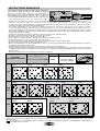 2
2
-
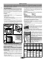 3
3
-
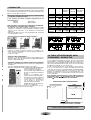 4
4
-
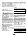 5
5
-
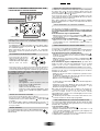 6
6
-
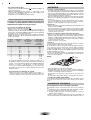 7
7
-
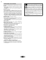 8
8
-
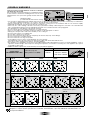 9
9
-
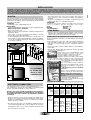 10
10
-
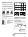 11
11
-
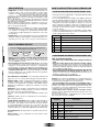 12
12
-
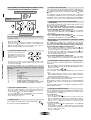 13
13
-
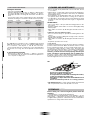 14
14
-
 15
15
-
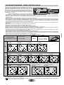 16
16
-
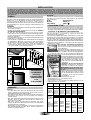 17
17
-
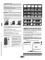 18
18
-
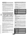 19
19
-
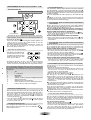 20
20
-
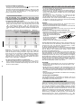 21
21
-
 22
22
-
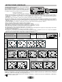 23
23
-
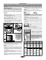 24
24
-
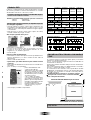 25
25
-
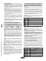 26
26
-
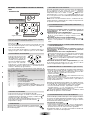 27
27
-
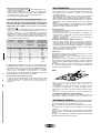 28
28
-
 29
29
-
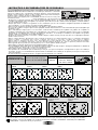 30
30
-
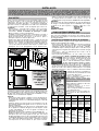 31
31
-
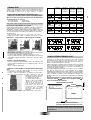 32
32
-
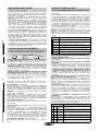 33
33
-
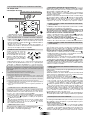 34
34
-
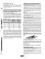 35
35
-
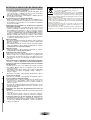 36
36
-
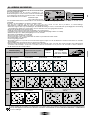 37
37
-
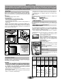 38
38
-
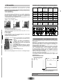 39
39
-
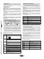 40
40
-
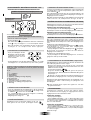 41
41
-
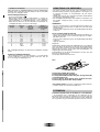 42
42
-
 43
43
-
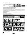 44
44
-
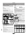 45
45
-
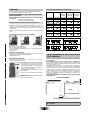 46
46
-
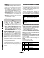 47
47
-
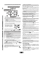 48
48
-
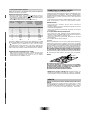 49
49
-
 50
50
-
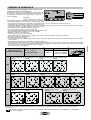 51
51
-
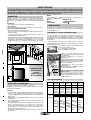 52
52
-
 53
53
-
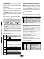 54
54
-
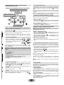 55
55
-
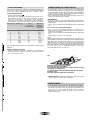 56
56
-
 57
57
-
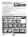 58
58
-
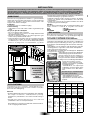 59
59
-
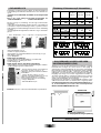 60
60
-
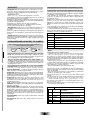 61
61
-
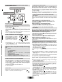 62
62
-
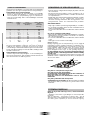 63
63
-
 64
64
-
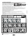 65
65
-
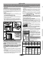 66
66
-
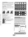 67
67
-
 68
68
-
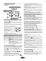 69
69
-
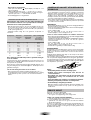 70
70
-
 71
71
-
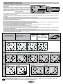 72
72
-
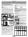 73
73
-
 74
74
-
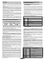 75
75
-
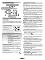 76
76
-
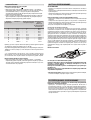 77
77
-
 78
78
-
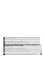 79
79


Candy PVC 460 C Le manuel du propriétaire
- Catégorie
- Plaques de cuisson
- Taper
- Le manuel du propriétaire
dans d''autres langues
- English: Candy PVC 460 C Owner's manual
- español: Candy PVC 460 C El manual del propietario
- Deutsch: Candy PVC 460 C Bedienungsanleitung
- Nederlands: Candy PVC 460 C de handleiding
- português: Candy PVC 460 C Manual do proprietário
- dansk: Candy PVC 460 C Brugervejledning
- svenska: Candy PVC 460 C Bruksanvisning
- suomi: Candy PVC 460 C Omistajan opas
Documents connexes
-
Candy PVD 633/1 X Manuel utilisateur
-
Candy pvd 6401 c Manuel utilisateur
-
-
-
-
-
-
-
Candy PC PVD604X E Manuel utilisateur
-
Autres documents
-
ROSIERES RVE 641 Le manuel du propriétaire
-
-
Brandt TV1203B Le manuel du propriétaire
-
Brandt TV1220B Le manuel du propriétaire
-
-
-
M-system MKK - 772 IX Le manuel du propriétaire
-
-
-