DCS BFG-30BGD-L-70845A Le manuel du propriétaire
- Catégorie
- Barbecues
- Taper
- Le manuel du propriétaire
Ce manuel convient également à


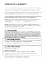
A MESSAGE TO OUR CUSTOMERS
Thank you for selecting this DCS Professional "Liberty Collection" Outdoor Appliance. Because of this appliance's
unique features we have developed this Use & Care and Installation Guide. It contains valuable information on
how to properly install, operate and maintain your new appliance for years of safe and enjoyable use.
To help serve you better, please fill out and submit your Product Registration by visiting our website at
www.dcsappliances.com and selecting "Customer Care" on the home page and then select "Product
Registration". In addition, keep this guide handy, as it will help answer questions that may arise as you use your
new appliance.
For your convenience, product questions can be answered by a DCS Customer Care Representative at
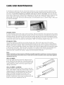
NOTE: Please write the Model, Code and Serial Numbers on this page for references (can be found on the inside,
right side panel behind the drip pan handle. See page 7.)
MODEL NUMBER CODE SERIAL NUMBER
NOTE: Inspect the product to verify that there is no shipping damage. If any damage is detected, call the shipper
and initiate a damage claim. DCS by Fisher & Paykel is not responsible for shipping damage.
DO NOT discard any packing material (box, pallet, straps) until the unit has been inspected.
WARNING!
Do not try lighting this appliance without reading the "Lighting Instructions" section of this manual.
Improper installation, adjustment, alteration, service or maintenance can cause property damage,
injury or death. Read the installation, operating and maintenance instructions thoroughly before use,
installing or servicing this equipment.This outdoor cooking gas appliance is not intended to be
installed in or on recreational vehicles, boats or in a non-ventilated room. For outdoor residence use
only.
WARNING
1. Do Not store or use gasoline or any other flammable vapors and liquids in the vicinity of
this or any other appliance.
2. An LP cylinder not connected for use shall not be stored in the vicinity of this or any
other appliance.
DANGER
If you smell gas:
1. Shut off gas to the appliance.
2. Extinguish any open flames.
3. Remove any covers in place over burners/griddle.
4. If odor continues, keep away from the appliance and immediately call your gas supplier
or your fire department.
PLEASE RETAIN THIS MANUAL FOR FUTURE REFERENCE.

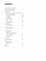
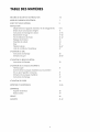
CONTENTS
SAFETY PRACTICES & PRECAUTIONS
OUTDOOR APPLIANCE MODELS
BEFORE USING YOUR APPLIANCE
3-5
6
7
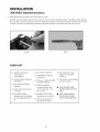
INSTALLATION
Locating Outdoor Appliance/Built-in Clearances 8-9
Built-in Construction Details 10
Cart Assembly Instructions 11-15
Gas Hook-up 16-19
Leak Testing 20-21
Burner Adjustment 22
Radiant Assembly 23
Sink 24
Side Shelf (optional) 25-26
Installer Checklist 26
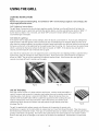
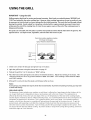
USING THE GRILL
Lighting Instructions 27
Use of the Grill 27-28
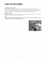
USING THE SIDE BURNER
Lighting Instructions
USING THE GRIDDLE
Thermocouple
Before Using the Griddle for the
First Time or to Re-season
Use of the Griddle
Lighting Instructions
USING THE SINK
CARE & MAINTENANCE
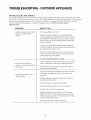
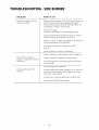
TROUBLESHOOTING
Outdoor appliance
Side Burner
SERVICE
WARRANTY
29
3O
30
30
31
32
33-36
37
38
39
40-41

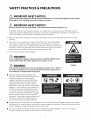
SAFETY PRACTICES & PRECAUTIONS
1.
2.
IMPORTANT SAFETY NOTICE!
Certain Liquid Propane dealers may fill liquid propane cylinders for usein the outdoor appliance beyond cylinder
filling capacity. This"Overfilling" may create a dangerous condition.
IMPORTANT SAFETY NOTICE!
Be sure to remove covers from grill, griddle or side burners before attempting to light or use.
"Overfilled"tanks can build up excess pressure. As a safety device, the tanks pressure relief valve will vent
propane gas vapor to relieve this excess pressure. This vapor is combustible and therefore can be ignited. To
reduce this danger, you should take the following safety precautions:
When you have your tank filled, be sure you tell the supplier to fill it to no more than 3/4 (75%) of its total
capacity.
If you own or use a spare tank, or have a disconnected tank, you should NEVER
store it near or under the outdoor appliance/cart unit or heat box, or near any
other ignition or heat source. A metallic sticker with this warning is provided with
the grill to remind you, your family and all others who may use your grill of these
safety precautions. Install this sticker close to your barbeque grill.
3. Do not store a full tank in direct sunlight.
WARNING!
Do not try lighting this appliance without reading the "LIGHTING INSTRUCTIONS"
section of this manual. This outdoor appliance is for outdoor use only.
WARNING!
Push and hold the igniter button, turn the selected burner knob to "HI" or "SEAR". If
burner does not light in 4 to S seconds turn knob"OFF"and wait S minutes for any
accumulated gas to dissipate before trying again.
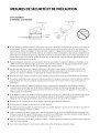
STICKER
Begin by insuring proper installation and
servicing. Follow the installation instructions
within this manual. Have your outdoor
appliance installed by a qualified technician.
Have the installer show you where the gas
supply shut-off valve is located so that you
know where to shut off the gas to the outdoor
appliance. If you smell gas, your installer has
not done a proper job of checking for leaks. If
the connections are not perfectly sealed, you
can have a small leak and therefore a faint gas
smell. Finding a leak is not a"do-it-yourself"
procedure. Some leaks can only be found with
the burner control in the "ON" position and
this must be done by a qualified technician.
Children should not be left alone or unattended in an area where the outdoor appliance is being used. Never
allow them to sit, stand or play on or around the outdoor appliance at any time. When in use, portions of the
outdoor appliance can get hot enough to cause severe burns.
Do not store items of interest to children around or below the outdoor appliance, in the cart or masonry
enclosure. Never allow children to crawl inside a cart or enclosure.

SAFETY PRACTICES & PRECAUTIONS
• Never let clothing, pot holders or other flammable materials come in contact with or too close to any grate,
burner or hot surface until it has cooled. Fabric may ignite and result in personal injury.
• Never attach or disconnect an LP cylinder, or move or alter gas fittings when the grill is in operation or is hot.
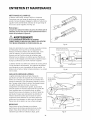
• Clean and perform general maintenance on the grill twice a year. Watch for corrosion, cracks, or insect activity.
Check the regulator, hoses, burner ports, air shutter, and venturi/valve section carefully. Always turn off gas at
the source (tank or supply line) prior to inspecting parts.
• After a period of storage or non-use (such as over the winter), the gas grill should be checked for gas leaks,
deterioration, proper assembly, and burner obstructions before using.
• Do not heat unopened food containers as a build-up of pressure may cause the container to burst.
• Always use a covered hand when taking off the lid and only do so slowly to allow heat and steam to escape.
• Never lean over an open outdoor appliance. When lighting a burner, always pay close attention to what you are
doing.
• After lighting burners, make sure burners are operating normally (see pages 21 and 22).
• When using the outdoor appliance, do not touch the outdoor appliance burner grate or immediate surrounding
area as these areas become extremely hot and could cause burns.
• Grease is flammable. Let hot grease cool before attempting to handle it. Avoid letting grease deposits collect in
the drip pan. Clean often.
For personal safety, wear proper apparel. Loose fitting garments or sleeves should never be worn while using
this appliance. Some synthetic fabrics are highly flammable and should not be worn while cooking. Only certain
types of glass, heat-proof glass ceramic, earthenware, or other glazed utensils are suitable for outdoor appliance
use. Use of some types of materials may break with sudden temperature changes. Use only on low or medium
heat settings according to the manufacturer's directions.
WARNING!
Spiders and insects can nest in the burners of this and any other outdoor appliance, and cause the gas to flow from
the front of the burner. The gas will flow from the front of the burner into the control panel. This isa very dangerous
condition which can cause a fire to occur behind the valve panel, thereby damaging the outdoor appliance
components and making it unsafe to operate.
WARNING!
Keep the area surrounding the outdoor appliance free from combustible materials, trash, or combustible fluids and
vapors such as gasoline or charcoal lighter fluid. Do not obstruct the flow of combustion and ventilation air.
WARNING!
Never use the outdoor appliance in windy conditions. If located in a consistently windy area (oceanfront,
mountaintop, etc.) a wind break will be required. Always adhere to the specified clearances listed.
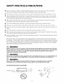
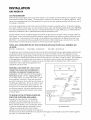
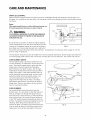
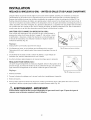
OUTDOOR APPLIANCE PLACEMENT
PREFERREDAIR FLOW
_ _ FLAME
`4_*,__*,i/_,_,4,_!_0 ,",0)F-"_ BURNER
0000000
@

SAFETY PRACTICES & PRECAUTIONS
Do not use aluminum foil to line drip pans, grates or radiants. This can severely upset combustion air flow or trap
excessive heat in the control area. The result of this can be melted knobs or damaged ignition components.
When using the side burners always use flat bottomed pans which are large enough to cover the side burner. Adjust
the flame so that it heats only the bottom of the pan to avoid ignition of clothing. Position handles inward away from
open edges of the unit to avoid burns associated with unintentionalspillovers. Hold the handle of the pan to prevent
movement of it when turning or stirring food. For proper lighting and performance of the burners, keep the ports
clean. It is necessary to clean them periodically for optimum performance.
Clean the outdoor appliance with caution. Avoid steam burns; do not use a wet sponge or cloth to clean the outdoor
appliance while it is hot. Some cleaners produce noxious fumes or can ignite if applied to a hot surface.
Be sure all outdoor appliance controls are turned off and the outdoor appliance is cool before using any type of
aerosol cleaner on or around the outdoor appliance. The chemical that produces the spraying action could, in the
presence of heat, ignite or cause metal parts to corrode.
Do not use the grill for cooking excessively fatty meats or products which promote flare-ups.
Never use outdoor appliance without the drip pan and grease tray in place and pushed all the way to the back.
Without the grease pan, hot grease could leak downward and produce a fire or explosion hazard.
Do not operate the outdoor appliance under unprotected combustible construction. Use only in well ventilated areas.
Do not use in buildings, garages, sheds, breezeway, covered structure or other such over head structures and
enclosed areas. This unit is for outdoor use only.
If a cart unit is stored indoors, ensure that it is cool, fold the optional side shelf(s) down, and never push or pull on
the side shelves. IfLP, the LP cylinder must be unhooked and stored outside in a well ventilated area, out of reach of
children.
• Do not use charcoal or lighter fluid in the outdoor appliance.
• Never use the outdoor appliance in a windy area.
• Never use a dented or rusty LP tank. Keep the ventilation openings of the cylinder enclosure free and clear from
debris.
• Use only dry potholders; moist or damp potholders on hot surfaces may cause burns from steam. Do not useatowel
or bulky cloth in place ofpotholders. Do not let potholderstouch hot portions of the outdoor appliance.
• Have an ABC rated Fire Extinguisher accessible - never attempt to extinguish a grease fire with water or ot her liquids.
• To avoid burns when cooking, use long handled BBQ tools.
• Do not move the appliance during its use.
• This unit is for outdoor use only! Do not operate in enclosed areas. This could result in carbon monoxide build-up
which would result in injury or death.
• When using the grill, be sure that all parts of the unit are firmly in place and that the grill is stable (can't be tipped
over).
To put out flare-ups, adjust the controls to lower the temperature
CALIFORNIA PROPOSITION 6S-WARNING: The burning of gas cooking fuel generates some by-products which are on
the list of substances which are known by the State of California to cause cancer or reproductive harm. California law
requires businesses to warn customers of potential exposure to such substances. To minimize exposure to these
substances, always operate this unit according to the Use and Care Guide, ensuring you provide good ventilation
when cooking with gas.
• This outdoor cooking gas appliance is not intended to be installed in or on recreational vehicles, trailers and/or boats.
Note:
This product must be installed by a licensed plumber or gas fitter when installed within the Commonwealth of
Massachusetts.

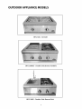
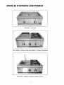
OUTDOOR APPLIANCE MODELS
BFG-30G - All-Grill
BFG-30BGD - Double Side Burner/Griddle
BFG-30BS - Double Side Burner/Sink

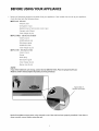
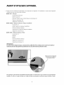
BEFORE USING YOUR APPLIANCE
1.
Remove all packaging materials and labels from your appliance. If the installer has not set up your appliance,
check that you have the following items:
• BFG-30G - All-Grill
- All-Grill cover
- Grill grates (5 pcs)
- Radiant trays to hold ceramic rods (2 pcs)
- Ceramic rods (28 pcs)
- Cover hanger (2 pcs)
• BFG-3OBGD - Side BurnerlGriddle
- Covers (2 pcs)
- Griddle grease cup
- Side burner grate
- Griddle flu cover
- Cover hanger (2 pcs)
• BFG-3OBS - Side BurnerlSink
- Covers (2 pcs)
- Faucet
- Drain plug
- Side burner grate
- Cover hanger (2 pcs)
- Burner caps (2 pcs)
NOTE:
If any of the listed items are missing, contact DCS at (888) 936-7872. Please be prepared with your
Model #, Serial # and description of product you have purchased.
Tag location of
Model # and Serial #
Read all installation instructions in this manual to see if the unit has been properly installed. If not done or
done correctly, correct before using the unit.

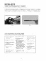
INSTALLATION
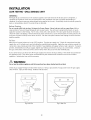
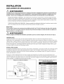
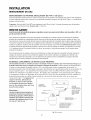
LOCATING OUTDOOR APPLIANCE/BUILT-IN CLEARANCES
LOCATION:
When determining a suitable location, take into account concerns such as exposure to wind (If located in a
windy area, a wind break must be provided to prevent poor burner performance or product damage.), proximity
to traffic paths and keeping any gas or electrical supply lines as short as possible. Locate the outdoor appliance
only in a well ventilated area. Do not install the outdoor appliance under overhead unprotected combustible
construction. Never locate the outdoor appliance ina building, garage, breezeway, shed, gazebo, lanai or other
such enclosed areas without an approved ventilation system. During heavy use, the outdoor appliance will
produce a lot of smoke and flames. Ensure there is adequate area for it to dissipate.
Important!
Gas fittings, regulator, and installer supplied shut-off valves must be used and easily accessible.
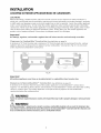
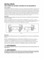
Clearances to Combustible* Construction (see definition on page 9):
A minimum of12" from the sides and a minimum of 12" from the back must be maintained from the outdoor
appliance above the cooking surface to adjacent vertical combustible* construction. (Fig. 01) Do not install
under unprotected combustible* construction.
--I Maintain .............. -- Maintain
12" from 12" from
combustible :ombustible
construction :onstruction
i
2,-:..........2s2, , 3,t
Maintain
12"from
Fig. 01
Important!
All outdoor appliances must have an insulated jacket to combustible island construction.
Clearances to Noncombustible** Construction (see definition on page 9):
A minimum of 3" clearance from the back of the outdoor appliance to noncombustible** construction is
required. It is desirable to allow at least 6" side clearance to noncombustible** construction above the cooking
surface or counter space. The outdoor appliance can be placed directly adjacent to noncombustible**
construction below the cooking surface.
WARNING!
Failure to maintain required clearances creates a fire hazard that may result in property damage or serious personal
injury.
WARNING!
If a Noncombustible** material such as metal is covering a combustible material such as wood, the minimum clear-
ance distance needs to be held to the wood. The presence of a Noncombustible** material inside the clearance zone
does not eliminate the minimum clearance zone to combustible material.

INSTALLATION
LOCATING BUILT-IN CLEARANCES
WARNING!
The appliances are designed to function in an open area. Recommended minimum clearances should be maintained
to all surfaces (combustible _ and noncombustible _*) for optimum performance. Noncombustible _* material within
the minimum clearance area could result in discoloration or deterioration.
*DEFINITION OF COMBUSTIBLE MATERIAL - Any materials of a building structure or decorative structure made of wood, compressed
paper, plant fibers, stucco or other materials that are capable of transferring heat or being ignited and burned. Such material shall be
considered combustible even though flame-proofed, fire-retardant treated, or painted surface or plastered.
**DEFINITION OF Noncombustible MATERIAL - Material which is not capable of being ignited and burned, such as materials consisting
entirely of, or a combination of, steel, iron, brick, tile, concrete, slate, and plaster (which is unpainted).
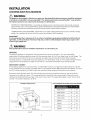
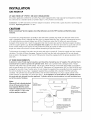
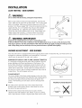
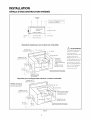
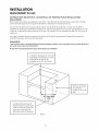
Important!
It is recommended that a minimum of 10 sq. inches of ventilation opening be provided for both the left and
right sides, as well as the back of enclosure (Fig. 02), in order to safely dissipate unburned gas vapors in the
event of a gas supply leak.
WARNING!
Note specific built-in enclosure ventilation requirements. See text and Fig. 02.
GENERAL
The outdoor appliance is designed for easy placement into masonry enclosures. For non-combustible
applications the outdoor appliance drops into the opening shown in Fig. 03 and hangs from its side flanges. The
deck must be level and flat. A deck is not required to support the unit from the bottom. When using the
insulated jacket in a combustible enclosure application, see the bottom of Fig. 03. The jacket assembly must be
supported from the bottom by a ledge on each side or a solid deck beneath the entire insulated jacket.
INSULATED JACKET:
If the outdoor appliance is to be placed into a combustible enclosure, an approved insulated jacket is required
and is available from your dealer. Insulated jacket is not required for BFG-30BS Side Burner Sink Model. Use only
the DCS insulated jacket (p/n #70859) which has specifically been designed and tested for this purpose.
Review the detail drawing shown (Fig. 03) and take into account the provisions shown for gas line hook-up
clearance in the right rear corner. It is recommended that ventilation holes are provided in the enclosure to
eliminate the potential build-up of gas in the event of a gas leak. The supporting ledges or deck must be level
and flat. The counter should also be level.
Ventilation Requirements:
2
10 in. Min. ventilation
on the back side
2
10 in. Min.ventilation 2
-10 in. Min. ventilation
left hand side on the right hand side
1" Min. Note: not drawn to scale
Opening for
access doors/drawers
Fig. 02
CUTOUTDIMENSIONSOFMATCHINGACCESSDOORS/DRAWERS:
ADN 20X24
ADN 20X30 28" 20"
ADN 20X36 34" 20"
ADN 20X48 46" 20"
ADR24 22" 20"
ADR36 34" 20"
ADR30 28" 20"
ADR48 46" 20"

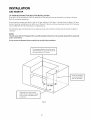
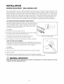
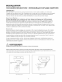
INSTALLATION
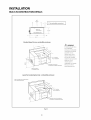
BUILT-IN CONSTRUCTION DETAILS
grill
exhaust
-- -- [ 12" (to combustible construction)
J
10-1/16"
J
2. ZII .........
i
Standard layout for non-combustible enclosure:
22-3/4"
for gas supply line
35-1/2"
Max.
NOTE: See page 9
for ventilation notes.
opening for access doors
(see page gfor ordering information)
_ WARNING!
If installing the grill into a
non-combustible
enclosure, all combustible
construction must still be
outside the 12 inch
clearance zone. If your
island is made of stucco
over the top of wooden
studs, the wood can not be
inside the 12 inch
clearance zone to
combustible, even though
the stucco is what is
touching the grill area.
Layout for insulated jacket only -corn bustible enclosure:
NOTE: See page 9 for insulated jacket
part ordering information.
_" min.
23-3/4"
." 3q/2" f_rXg_:°Pupply gine
_sPeeng:gef°9;cCCe;dd°°gl/r _rc;we rt.Son)
Fig.03
10

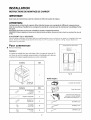
INSTALLATION
CART ASSEMBLY INSTRUCTIONS
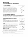
IMPORTANT:
Read all instructions before you begin. Do not jump ahead or skip any step.
CAUTION:
Some parts have sharp edges; care must be taken when handling the various components to
avoid injury. Please read safety information provided in these instructions before beginning
assembly. Wear gloves when handling.
Two or more people should work together to assemble the cart and All-Grill, Double Side
Burner/Sink, or Double Side Burner/Griddle.
NOTE: Avoid using optional side shelf to move cart. Push or pull cart by grasping corners of head.
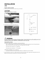
LOCATING THE CART
For proper use, this product should be installed/positioned on a flat ground or patio. Unevenness such as
bumps, cracks and protrusions should be 1/4" or less. Refer to Fig. 04 for rec uired flat area dimensions.
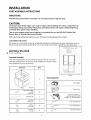
Getting Started
Remove packaging.
Contents Included:
Your cart is packaged in one box.The box contains your 30"cart and a
universal hardware kit to be used for head installation and may contain
extra hardware for your convenience.
Contents
i - z _ _//_
. ._ 30" Cart
Qty.
Machined Phillips
screws 13
10-24X1/2"
Bracket, Tab 2
Bolt Hex
1/4-20-1/2" 2
(_ Washer 4
.313 x .750
Nut Hex 2
1/4-20
11
TOP VIEW (with drawers open)
CAD 30= 30"
CAD 36= 36"
CAD48 =48"
o ©
Fig.04
Tools Required:
Work Gloves
Power Screwdriver or
Variable Speed Drill with
Phillips - tip #2 Attachment
5/32"Allen Wrench
3/16" Allen Wrench
3/32"Allen Wrench
Eye Goggles

INSTALLATION
CART ASSEMBLY INSTRUCTIONS
Step 1
Link Carts Together (optional)
(To link two or more CAD carts, the following instructions must be done first, using
the hardware provided, before installing the top modules.)
To link your carts together - hand tighten 2 bolts, 4 washers, and 2 nuts on the front and back sides of the carts
as shown in Fig. 04. Carefully wrench tighten fasteners once carts are aligned with each other.
CAUTION:
Once the carts are linked, they cannot be moved. Moving the carts once linked could damage the carts.
Head of bolt with washer
Head of bolt with washer
End of bolt with nut and washer End of bolt with nut and washer
12

1.
INSTALLATION
CART ASSEMBLY INSTRUCTIONS
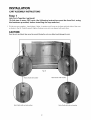
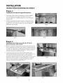
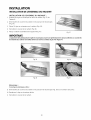
Step 2
Outdoor Appliance Head Preparation
First you will need to remove the angle brackets from the side
of the unit and replace them with cart mount brackets
(Fig. 06). Unit is shipped prepared for island installation.
2.
Install the bracket tab on both sides of the appliance head
using 8 of the 10-24 x 1/2" screws. Install each bracket with 4
screws on each side of the outdoor appliance head
(Fig. 07 and 08).
1.
Fig. 07
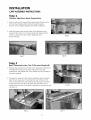
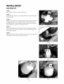
Step 3
Head Placement onto Cart (2 Persons Required)
Remove drip tray/pan (Fig. 09) and other removable components
(to lighten the load) such as grates, top burner caps and
components, and griddle flue cover, radiant tray and grill burner
for easier handling.
2.
Two persons required to lift head (sink module shown). Placing
head on cart, place rear of head over the rear of the cart first
(Fig. 10). Then allow the rear side tabs to first locate in the slots
on the top of the cart sides. The other tabs will locate in the
middle and front slots as the head is lowered into position on the
cart (Fig. 11).
Fig. 10
13
Fig.06
Fig.08
Fig. 11
Fig. 09

3.
INSTALLATION
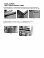
CART ASSEMBLY INSTRUCTIONS
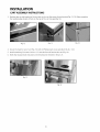
Position tabs on side bracket to fit into slots on the cart (be aware of pinch points)(Fig. 12-13). When complete,
the leading ledge should sit flush on the top of the cart (no gap)(Fig. 14).
Fig. 12 Fig. 13 Fig. 14
4. Secure the head to rear of cart (Fig. 15) with (2) Phillips-head screws provided (10-24 x 1/2").
5. Install remaining (3) screws (10-24 x 1/2") into the front of head to the cart (Fig. 16).
6. Slide drip tray/pan back into place and reinstall parts removed in Step 3, #1.
Fig. 15
14
Fig. 16

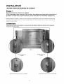
INSTALLATION
CART ASSEMBLY INSTRUCTIONS
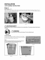
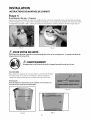
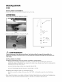
Step 4
Gas Hookup - LP
Make sure the cart assembly is stable. Open the tank drawer. Place the LP tank into location as shown in Fig. 17.
Connect the regulator assembly to the tank connection with all appliances valves in the "OFF" position. Open the
tank valve and test for gas leaks (Fig. 18).
Fig. 17 Fig. 18
FORYOUR SAFETY
To prevent personal injury or damage to the drawers, do not overload them. The maximum rating of each drawer is
35 pounds.
WARNING!
Do not push down on the top of the drawers. The unit could tip forward.
COVER HANGER
To use the cover hangers provided, first place the cover hanger
into the slot on the side or rear of your Cart (Fig. 19). Then hang
the cover in either direction. (Fig. 20 or 21).
Note:
Do not move the cart while the covers are hung. This could cause
the covers to fall off the hangers and damage the covers.
Fig. 20
15
Fig. 21
Fig. 19

INSTALLATION
GAS HOOK-UP
GAS REQUIREMENT
Verify the type of gas supply to be used, either natural or LID,and make sure the marking on the appliance rating
plate agrees with that of the supply. The rating plate is located on the bottom of the outdoor appliance. Never
connect an unregulated gas line to the appliance. You must use the gas regulator provided with the unit even if
the supply is controlled.
An installer-supplied gas shut-off valve must be installed in an easily accessible location. All installer supplied
parts must conform to local codes, or in the absence of local codes, with the National Electrical Code, ANSI/NFPA
70 or the Canadian Electrical Code, CSA C22.1, and the National Fuel Gas Code, ANSI Z223.1 or CAN/CGA-B149.1
Natural Gas Installation Code or CAN/CGA-B149.2 Propane Installation Code.
All pipe sealants must be an approved type and resistant to the actions of LPgases. Never use pipe sealant on
flare fittings. All gas connections should be made by a qualified technician and in accordance with local codes
and ordinances. In the absence of local codes, the installation must comply with the National Fuel Gas Code,
ANSIZ223.1. Gas conversion kits are available from the factory. When ordering gas conversion kits, have the
model number, and the type of gas (natural or LP) from your outdoor appliance.
TOTAL GAS CONSUMPTION OF THE OUTDOOR APPLIANCE WITH ALL BURNERS ON
HI/SEAR:
BFG-30G - 50,000 Btu/hr BFG-30BGD - 49,000 Btu/hr BFG-30BS - 34,000 Btu/hr
The appliance and its individual shut-off valve must be disconnected from the gas supply piping system during
any pressure testing of that system at test pressures in excess of 1/2 PSIG (3.5 kPa.) The appliance must be
isolated from the gas supply piping system by closing its individual manual shut-off valve during any pressure
testing of the gas supply piping system at test pressures equal to or less than 1/2 PSIG (3.5 kPa.). The installation
of this appliance must conform with local codes or, in the absence of local codes, with the National Fuel Gas
Code, ANSI Z223.1. Installation in Canada must be in accordance with the Standard Canl-b149.1 and/or .2
(installation code for gas burning appliances and
equipment) and local codes.
NATURAL GAS HOOK UP: (THIS TYPE OF
CONNECTION SHOULD BE PERFORMED BY A
CERTIFIED OR LICENSED TECHNICIAN ONLY.)
Connection: 1/2" NPT male with 3/8" flare adapter.
Operating pressure: 4.0" W.C. Supply pressure: 5"
to 14" water column. If in excess of 14" W.C., a step-
down regulator is required. Check with your local
gas utility company or local codes for instructions on
installing gas supply lines. Be sure to check on type
and size of run, and how deep to bury the line. If
the gas line is too small, the outdoor appliance will
not function properly. Any joint sealant used must
be an approved type and be resistive to the actions
of natural gases.
TO HOOK-UP THE FITTINGS SUPPLIED
WITH THE OUTDOOR APPLIANCE:
Assemble as shown (Fig. 22). Use threading
compound on male threads only. Do not use
threading compound on the male end of the 1/2"
NPT to 3/8 flare adapter. Useasecond pipe wrench
to hold the outdoor appliance inlet pipe to avoid
shifting any internal gas lines of the outdoor
appliance. Ensure that the regulator arrow points in
c t
ottomountJ
coupllng
Threading compound "_,_ /
must be resistant to LPgas /_ 1/2" NPTx
_ 2.0"
Nipple
__ Regulator
1/2" NPT x 5.0" 4.0" W.C.
Nipple
\Z/_ Adapter 1/2" NPT
/ to 3/8" flare fitting
Installer supplied shut-off __
accessible_valvemust be easily _ _ Do not put threading
compound on these
_./' threads
_lnstallation must conform with local
codes or with the National Fuel GasCode
ANSIZ223.1 or the CAN/CGA-B149.2
Propane Installation Code
Fig. 22 Natural Gas
the direction of gas flow towards the unit, away from the supply. Do not forget to place the installer-supplied
gas valve in an accessible location.
16

INSTALLATION
GAS HOOK-UP
LP GAS HOOK UP (TYPE 1 OR QCC1 REGULATOR):
All outdoor appliances orificed for use with LP gas come equipped with a high capacity hose/regulator assembly
for connection to a standard 20 lb. LP cylinder (Type 1). The LP tank is not included.
Connection: 1/2" NPT male with a 3/8" Flare adapter (included). LP Hose with a quick disconnect and fittings are
included. Operating pressure: 11.0" W.C.
CAUTION!
Before connecting LP tank to regulator, check that all burners are in the"OFF" position and the lid has been
removed.
To connect the LP regulator/hose assembly to the tank/valve assembly, first make sure the main valve on the
tank is completely closed. Although the flow of gas is stopped when the Type 1 system is disconnected as part
of its safety feature, you should always turn off the LP tank main valve (Fig. 23) after each use and during
transport of the tank or unit. Insert the regulator inlet into the tank valve and turn the black coupler clockwise
until the coupler tightens up. Do not overtighten the coupler. Turn the main tank valve on, push and turn the
burner control valves on the unit to the "HI" position for about 20 seconds to allow the air in the system to
purge, turn valves off and wait 5 minutes before attempting to light the burners.
To disconnect the coupler, first make sure the main tank valve is turned off. Grasp the coupler and turn counter
clockwise. The inlet will then disengage. Remove the inlet from the tank valve opening if it has not already
done so when it disengaged. Your local LP filling station should be equipped with the proper equipment to fill
your tank.
LP TANK REQUIREMENTS:
A dented or rusty LP tank may be hazardous and should be checked by your LP supplier. The cylinder that is
used must have a collar to protect the cylinder valve. Never use a cylinder with a damaged valve. Always
check for leaks after every LP tank change. The LP gas cylinder must be constructed and marked in accordance
with the specifications for LP gas cylinders of the U.S. Department of Transportation (DOT or CAN/CSA-B339) and
designed for use with a Type 1 system only. Do not change the regulator/hose assembly from that supplied with
the unit or attempt to use a Type 1 equipped regulator/hose assembly with a standard 510 POL tank/valve
assembly. The cylinder must be provided with a shut-off valve terminating in a LP gas supply cylinder valve
outlet specified, as applicable, for connection Type 1. If the appliance is stored indoors, the cylinder must be
disconnected and removed from the appliance. Cylinders must be stored outdoors in a well-ventilated area
out of the reach of children.
Note:
When an LP unit is directly attached
into an LP house system, the step-
down regulator MUST be used to
reduce the supply pressure to a max.
14" W.C. and min. 1I" W.C. to the
outdoor appliance regulator.
Threading
compound must be
resistant to LPgas _ /
• 1/2"female
Bottom of unit
_._ NPTx 3/8" male flare
_ (installed on unit)
Type 1 Regulator _ z_ /_ Note: Do not put
• _ / f threading compound
Main TankValve _ _ II on male threads of flare
J i ] assembly 11" W.C.
/ l_. _1 (installed on unit)
TypelTank l_ I
k J _lnstallation must conform with
_ local codes or with the National
Fuel Gas Code ANSI Z223.1 orthe
CAN/CGA-B149.2 Propane
Installation Code
17
Fig. 23 LP Gas

INSTALLATION
GAS HOOK-UP
LP TANK RESTRAINT FOR BUILT-IN INSTALLATION
If the grill is to be installed in a Built-in application, then the grill must be installed in accordance with the
Built-in installation guidelines.
If you intend to operate your Built-in grill on LP gas utilizing a 201b Type cylinder, then the Built-in LPtank
restraint must be installed prior to initial use of the grill. If you do not have one please contact DCS Customer
Care at (888) 936-7872 for information on obtaining one.
The following steps will illustrate how to properly locate and install the LP tank restraint within the Built-in
enclosure.
NOTE:
The grill comes with the LP Regulator/Hose assembly installed at the factory. The assembly, along with the entire grill
system, is leak tested.
Do not remove the Regulator/Hose assembly from the grill during installation.
The maximum distance from the center
of the manifold cut out to the center of
the tank restraint is 18 inches.
Tank Restraint can be placed
within this area without causing
stress on the LP regulator hose
connection.
', 18" max.
Center of manifold
cut out projected to
floor of the island.
Fig.24
18

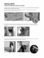
INSTALLATION
GAS HOOK-UP
STEP I
Place the tank restraint in the island (Fig. 25).
STEP 2
Locate the tank restraint in the island within the recommended area
(Fig. 24 and 26).
STEP 3
Once located, secure to the bottom of the island using all eight hole
locations provided on the restraint. Wood screws can be used for
wooden floors or I/4 inch diameter anchor screws or bolts may be
used if the floor is concrete or masonry (Fig. 27).
STEP 4
When secure, place the LP cylinder into the tank restraint making
sure to seat the tank all the way down, securely affixing the tank in
the restraint (Fig. 28).
STEP 5
Attach the regulator hose assembly and operate the grill normally as
described in the Use and Care manual (Fig. 29).
Fig.28
19
Fig.25
Fig. 26
Fig. 27
Fig.29
La page est en cours de chargement...
La page est en cours de chargement...
La page est en cours de chargement...
La page est en cours de chargement...
La page est en cours de chargement...
La page est en cours de chargement...
La page est en cours de chargement...
La page est en cours de chargement...
La page est en cours de chargement...
La page est en cours de chargement...
La page est en cours de chargement...
La page est en cours de chargement...
La page est en cours de chargement...
La page est en cours de chargement...
La page est en cours de chargement...
La page est en cours de chargement...
La page est en cours de chargement...
La page est en cours de chargement...
La page est en cours de chargement...
La page est en cours de chargement...
La page est en cours de chargement...
La page est en cours de chargement...
La page est en cours de chargement...
La page est en cours de chargement...
La page est en cours de chargement...
La page est en cours de chargement...
La page est en cours de chargement...
La page est en cours de chargement...
La page est en cours de chargement...
La page est en cours de chargement...
La page est en cours de chargement...
La page est en cours de chargement...
La page est en cours de chargement...
La page est en cours de chargement...
La page est en cours de chargement...
La page est en cours de chargement...
La page est en cours de chargement...
La page est en cours de chargement...
La page est en cours de chargement...
La page est en cours de chargement...
La page est en cours de chargement...
La page est en cours de chargement...
La page est en cours de chargement...
La page est en cours de chargement...
La page est en cours de chargement...
La page est en cours de chargement...
La page est en cours de chargement...
La page est en cours de chargement...
La page est en cours de chargement...
La page est en cours de chargement...
La page est en cours de chargement...
La page est en cours de chargement...
La page est en cours de chargement...
La page est en cours de chargement...
La page est en cours de chargement...
La page est en cours de chargement...
La page est en cours de chargement...
La page est en cours de chargement...
La page est en cours de chargement...
La page est en cours de chargement...
La page est en cours de chargement...
La page est en cours de chargement...
La page est en cours de chargement...
La page est en cours de chargement...
La page est en cours de chargement...
La page est en cours de chargement...
La page est en cours de chargement...
La page est en cours de chargement...
La page est en cours de chargement...
La page est en cours de chargement...
-
 1
1
-
 2
2
-
 3
3
-
 4
4
-
 5
5
-
 6
6
-
 7
7
-
 8
8
-
 9
9
-
 10
10
-
 11
11
-
 12
12
-
 13
13
-
 14
14
-
 15
15
-
 16
16
-
 17
17
-
 18
18
-
 19
19
-
 20
20
-
 21
21
-
 22
22
-
 23
23
-
 24
24
-
 25
25
-
 26
26
-
 27
27
-
 28
28
-
 29
29
-
 30
30
-
 31
31
-
 32
32
-
 33
33
-
 34
34
-
 35
35
-
 36
36
-
 37
37
-
 38
38
-
 39
39
-
 40
40
-
 41
41
-
 42
42
-
 43
43
-
 44
44
-
 45
45
-
 46
46
-
 47
47
-
 48
48
-
 49
49
-
 50
50
-
 51
51
-
 52
52
-
 53
53
-
 54
54
-
 55
55
-
 56
56
-
 57
57
-
 58
58
-
 59
59
-
 60
60
-
 61
61
-
 62
62
-
 63
63
-
 64
64
-
 65
65
-
 66
66
-
 67
67
-
 68
68
-
 69
69
-
 70
70
-
 71
71
-
 72
72
-
 73
73
-
 74
74
-
 75
75
-
 76
76
-
 77
77
-
 78
78
-
 79
79
-
 80
80
-
 81
81
-
 82
82
-
 83
83
-
 84
84
-
 85
85
-
 86
86
-
 87
87
-
 88
88
-
 89
89
-
 90
90


DCS BFG-30BGD-L-70845A Le manuel du propriétaire
- Catégorie
- Barbecues
- Taper
- Le manuel du propriétaire
- Ce manuel convient également à
dans d''autres langues
Documents connexes
-
DCS BFGC30BGDN Le manuel du propriétaire
-
DCS GDE1-30-N Guide d'installation
-
DCS BH148RN Guide d'installation
-
-
-
-
-
-
DCS BGC30BQN Guide d'installation
-
