KitchenAid KBNU367TSS0 Le manuel du propriétaire
- Catégorie
- Barbecues
- Taper
- Le manuel du propriétaire
Ce manuel convient également à

OUTDOOR GRILLS
FREESTANDING AND BUILT-IN
Installation Instructions and Use & Care Guide
For questions about features, operation/performance, parts, accessories or service, call: 1-800-422-1230
or visit our website at www.kitchenaid.com
In Canada, for assistance, installation and service, call: 1-800-807-6777
or visit our website at www.KitchenAid.ca
GRILS D'EXTÉRIEUR
AUTOPORTANTS ET ENCASTRÉS
Instructions d’installation et Guide d’utilisation et d’entretien
Au Canada, pour assistance, installation ou service composez le 1-800-807-6777
ou visitez notre site web à www.KitchenAid.ca
Table of Contents/Table des matières.............................................................................2
Models/Modèles KFRU368T, KFRU488T, KBNU367T, KBNU487T
W10110725C
IMPORTANT:
Save for local electrical inspector's use.
Installer: Leave installation instructions with the homeowner.
Homeowner: Keep installation instructions for future reference.
IMPORTANT :
À conserver pour consultation par l'inspecteur local des installations électriques.
Installateur : Remettre les instructions d'installation au propriétaire.
Propriétaire : Conserver les instructions d'installation pour référence ultérieure.

2
TABLE OF CONTENTS
OUTDOOR GRILL SAFETY............................................................3
INSTALLATION REQUIREMENTS................................................5
Tools and Parts ............................................................................5
Tools and Parts ............................................................................5
Location Requirements................................................................5
Product Dimensions.....................................................................6
Built-In Outdoor Grill Enclosure...................................................6
Cabinet Dimensions.....................................................................6
Electrical Requirements ...............................................................9
Gas Supply Requirements.........................................................10
Gas Connection Requirements..................................................11
Gas Connection Requirements..................................................12
INSTALLATION INSTRUCTIONS................................................12
Style 1 - Freestanding Outdoor Grill Installation........................12
Style 2 - Built-in Outdoor Grill Installation .................................15
Check and Adjust the Burners...................................................17
OUTDOOR GRILL USE ................................................................18
Using Your Outdoor Grill............................................................18
Using Your Infrared Sear Burner................................................19
Using Your Side Burner .............................................................20
Using Your Rotisserie.................................................................20
Rotisserie Cooking Tips .............................................................22
Using Your Smoker Box ............................................................23
Hood Lights................................................................................23
USING YOUR WARMING DRAWER ...........................................23
Control Knob ..............................................................................23
Moist-Dry Slide Control..............................................................24
Setting the Controls ...................................................................24
Warming Cookware ...................................................................25
Warming Pans and Positioning Rack ........................................25
Proofing Bread ...........................................................................25
Slow Cook Function...................................................................25
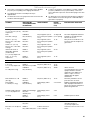
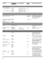
TIPS FOR OUTDOOR GRILLING ................................................26
Cooking Methods.......................................................................26
Grilling Chart...............................................................................27
OUTDOOR GRILL CARE .............................................................28
Changing the Light Bulb ............................................................28
General Cleaning........................................................................29
Drawer Slides .............................................................................31
Drawer Removal.........................................................................31
TROUBLESHOOTING ..................................................................31
ASSISTANCE OR SERVICE.........................................................32
In the U.S.A. ...............................................................................32
Accessories................................................................................32
In Canada ...................................................................................32
WARRANTY ..................................................................................33
TABLE DES MATIÈRES
SÉCURITÉ DU GRIL D'EXTÉRIEUR ...........................................35
EXIGENCES D'INSTALLATION...................................................37
Outillage et pièces......................................................................37
Outillage et pièces......................................................................37
Exigences d'emplacement.........................................................37
Dimensions du produit...............................................................38
Enceinte du gril d'extérieur encastré .........................................38
Dimensions du placard ..............................................................38
Spécifications électriques ..........................................................41
Spécifications de l'alimentation en gaz .....................................42
Exigences concernant le raccordement au gaz ........................43
Exigences concernant le raccordement au gaz ........................44
INSTRUCTIONS D'INSTALLATION.............................................44
Style 1 - Installation du gril d'extérieur autoportant ..................44
Style 2 - Installation du gril d'extérieur encastré .......................47
Contrôle et réglage des brûleurs................................................49
UTILISATION DU GRIL D'EXTÉRIEUR.......................................51
Utilisation du gril d'extérieur.......................................................51
Utilisation du brûleur à infrarouge..............................................53
Utilisation du brûleur latéral........................................................53
Utilisation du tournebroche........................................................54
Conseils de cuisson à l’aide du tournebroche ..........................55
Utilisation du fumoir ...................................................................56
Lampes sous le capot................................................................56
UTILISATION DU TIROIR-RÉCHAUD.........................................57
Bouton de commande ...............................................................57
Curseur de réglage Moist-Dry (humide-sec)..............................57
Réglage des commandes ..........................................................57
Ustensiles de réchauffage..........................................................58
Ustensiles de réchauffage et grille de positionnement..............58
Levée du pain.............................................................................59
Fonction de cuisson lente ..........................................................59
CONSEILS POUR L'UTILISATION DU GRIL D'EXTÉRIEUR ....60
Méthodes de cuisson.................................................................60
Tableau de cuisson au gril .........................................................61
ENTRETIEN DU GRIL D'EXTÉRIEUR .........................................63
Changement de l'ampoule d'éclairage......................................63
Nettoyage général ......................................................................63
Glissières de tiroir.......................................................................65
Dépose du tiroir..........................................................................65
DÉPANNAGE.................................................................................66
ASSISTANCE OU SERVICE.........................................................66
Au Canada..................................................................................66
Accessoires ................................................................................67
GARANTIE.....................................................................................67

3
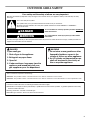
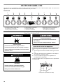
OUTDOOR GRILL SAFETY
You can be killed or seriously injured if you don't immediately
You
can be killed or seriously injured if you don't
follow
All safety messages will tell you what the potential hazard is, tell you how to reduce the chance of injury, and tell you what can
happen if the instructions are not followed.
Your safety and the safety of others are very important.
We have provided many important safety messages in this manual and on your appliance. Always read and obey all safety
messages.
This is the safety alert symbol.
This symbol alerts you to potential hazards that can kill or hurt you and others.
All safety messages will follow the safety alert symbol and either the word “DANGER” or “WARNING.”
These words mean:
follow instructions.
instructions.
DANGER
WARNING
If you smell gas:
1. Shut off gas to the appliance.
2. Extinguish any open flame.
3. Open lid.
4. If odor continues, keep away from the
appliance and immediately call your
gas supplier or your fire department.
DANGER
WARNING
1. Do not store or use gasoline or other
flammable liquids or vapors in the
vicinity of this or any other appliance.
2. An LP cylinder not connected for use
shall not be stored in the vicinity of
this or any other appliance.
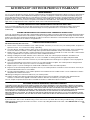
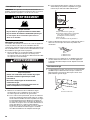
State of California Proposition 65 Warnings:
WARNING: This product contains a chemical known to the State of California to cause cancer.
WARNING: This product contains a chemical known to the State of California to cause birth defects or other reproductive harm.
In the State of Massachusetts, the following installation instructions apply:
■ Installations and repairs must be performed by a qualified or licensed contractor, plumber, or gasfitter qualified or licensed by
the State of Massachusetts.
■ If using a ball valve, it shall be a T-handle type.
■ A flexible gas connector, when used, must not exceed 3 feet.

4
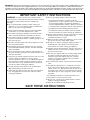
IMPORTANT: This grill is manufactured for outdoor use only. For grills that are to be used at elevations above 2000 ft (609.6 m) orifice
conversion is required. See “Gas Supply Requirements” section. It is the responsibility of the installer to comply with the minimum
installation clearances specified on the model/serial rating plate. The model/serial rating plate for built-in models can be found on the
right-hand side of the grill. The model/serial rating plate for freestanding models can be found on the right-hand inside cabinet wall.
SAVE THESE INSTRUCTIONS
IMPORTANT SAFETY INSTRUCTIONS
WARNING:
To reduce the risk of fire, electrical shock,
injury to persons, or damage when using the outdoor cooking
gas appliance, follow basic precautions, including the
following:
■
Do not install portable or built-in outdoor cooking gas
appliances in or on a recreational vehicle, portable trailer,
boat or in any other moving installation.
■
Always maintain minimum clearances from combustible
construction, see “Location Requirements” section.
■
The outdoor cooking gas appliance shall not be located
under overhead unprotected combustible construction.
■
This outdoor cooking gas appliance shall be used only
outdoors and shall not be used in a building, garage, or any
other enclosed area.
■
Keep any electrical supply cord and fuel supply hose away
from any heated surfaces.
■
Keep outdoor cooking gas appliance area clear and free
from combustible materials, gasoline and other flammable
vapors and liquids.
■
Do not obstruct the flow of combustion and ventilation air.
Keep the ventilation openings of the cylinder enclosure free
and clear from debris.
■
Inspect the gas cylinder supply hose before each use of the
outdoor cooking gas appliance. If the hose shows
excessive abrasion or wear, or is cut, it MUST be replaced
before using the outdoor cooking gas appliance. Contact
your dealer and use only replacement hoses specified for
use with the outdoor cooking gas appliance.
■
Visually check the burner flames. They should be blue.
Slight yellow tipping is normal for LP gas.
■
Check and clean burner/venturi tube for insects and insect
nest. A clogged tube can lead to fire under the outdoor
cooking gas appliance.
■
The LP gas supply cylinder to be used must be:
- constructed and marked in accordance with the
Specification for LP Gas Cylinders of the U.S. Department
of Transportation (DOT) or the National Standard of
Canada, CAN/CSA-B339, Cylinders, Spheres, and Tubes
for Transportation of Dangerous Goods; and Commission.
- provided with a listed overfilling prevention device.
- provided with a cylinder connection device compatible
with the connection for outdoor cooking gas appliances.
■
Always check connections for leaks each time you connect
and disconnect the LP gas supply cylinder. See
“Installation Instructions” section.
■
When the outdoor cooking gas appliance is not in use, the
gas must be turned off at the supply cylinder.
■
Storage of an outdoor cooking gas appliance indoors is
permissible only if the cylinder is disconnected and
removed from the outdoor cooking gas appliance.
■
Cylinders must be stored outdoors and out of the reach of
children and must not be stored in a building, garage, or
any other enclosed area.
■
The pressure regulator and hose assembly supplied with
the outdoor cooking gas appliance must be used. A
replacement pressure regulator and hose assembly
specific to your model is available from your outdoor
cooking gas appliance dealer.
■
Gas cylinder must include a collar to protect the cylinder
valve.
■
For appliances designed to use a CGA791 Connection:
Place a dust cap on cylinder valve outlet whenever the
cylinder is not in use. Only install the type of dust cap on
the cylinder valve outlet that is provided with the cylinder
valve. Other types of caps or plugs may result in leakage
of propane.
If the following information is not followed exactly, a fire
causing death or serious injury may occur.
■
Do not store a spare LP gas cylinder under or near this
outdoor cooking gas appliance.
■
Never fill the cylinder beyond 80 percent full.

5
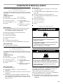
INSTALLATION REQUIREMENTS
Tools and Parts
Style 1 - Freestanding Outdoor Grills
Gather the required tools and parts before starting installation.
Read and follow the instructions provided with any tools listed
here.
Tools Needed
Parts Supplied
■ Gas pressure regulator/hose assembly set for 11" WCP LP
gas (attached to manifold).
■ Rotisserie motor mounting bracket
■ Rotisserie motor
■ Rotisserie forks
■ Rotisserie spit
■ Smoker box
■ 2 warming drawer pans
■ 1 single-prong plug/500 mAmp transformer assembly
Parts Needed
■ 20 lb LP gas fuel tank
Tools and Parts
Style 2 - Built-In Outdoor Grills
Gather the required tools and parts before starting installation.
Read and follow the instructions provided with any tools listed
here.
Tools Needed
Parts Needed
■ Gas line shutoff valve
■ ½" male pipe thread nipple for connection to pressure
regulator
■ LP gas-resistant pipe-joint compound
■ CSA design-certified outdoor flexible stainless steel
appliance connector (4-5 ft [1.2-1.5 m]) or rigid gas supply
line as needed.
Parts Supplied
■ Convertible regulator set for 4" WCP Natural gas.
■ 1 single-prong plug/5,000 mAmp transformer assembly for
the grill
■ Rotisserie motor mounting bracket
■ 1 single-prong plug/500 mAmp transformer assembly for the
rotisserie
■ Rotisserie motor
■ Rotisserie forks
■ Rotisserie spit
■ Smoker box
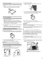
Location Requirements
Select a location that provides minimum exposure to wind and
traffic paths. The location should be away from strong draft
areas.
Do not obstruct flow of combustion and ventilation air.
Clearance to combustible construction for built-in and
freestanding outdoor grills:
■ A minimum of 24" (58 cm) must be maintained between the
front of the grill hood, sides and back of the grill and any
combustible construction.
■ A 24" (58 cm) minimum clearance must also be maintained
below the cooking surface and any combustible construction.
Rotisserie
A 6" (15.2 cm) minimum clearance is needed for the rotisserie
motor.
A grounded, 3-prong outlet located to the left of the grill is
required. See “Electrical Requirements” section.
■ Tape measure
■ Small, flat-blade screwdriver
■ Flat-blade screwdriver
■ #2 and #3 Phillips screwdriver
■ Level
■ Wrench or pliers
■ Pipe wrench
■ Scissors or cutting pliers
(to remove tiedowns)
■ Noncorrosive leak-
detection solution
■ Tape measure
■ Small, flat-blade screwdriver
■ Flat-blade screwdriver
■ #2 and #3 Phillips screwdriver
■ Level
■ Wrench or pliers
■ Pipe wrench
■ Scissors or cutting pliers
(to remove tiedowns)
■ Noncorrosive leak-
detection solution
WARNING
Explosion Hazard
Do not store fuel tank in a garage or indoors.
Do not store grill with fuel tank in a garage or indoors.
Failure to follow these instructions can result in death,
explosion, or fire.
WARNING
Fire Hazard
Do not use grill near combustible materials.
Do not store combustible materials near grill.
Doing so can result in death or fire.

6
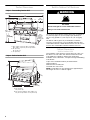
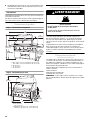
Product Dimensions
Style 1 - Freestanding Outdoor Grill
Style 2 - Built-In Outdoor Grill
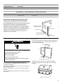
Built-In Outdoor Grill Enclosure
The enclosure for the built-in outdoor grill is to be a minimum of
11" (28.0 cm) high x 23" (58.4 cm) deep x [39" (99.0 cm) for
36" (91.4 cm) grill and 51" (129.5 cm) for 48" (121.9 cm) grill]
wide.
This built-in outdoor grill is only for installation in a built-in
enclosure constructed only of noncombustible materials. Non-
combustible materials could be brick, firewall or steel. Do not use
wood or other combustible materials for built-in enclosure.
Cabinet Dimensions
Built-In Outdoor Grills
The installation of this grill must conform with local codes or, in
the absence of local codes, with either the National Fuel Gas
Code, ANSI Z223.1/NPFA 54, Natural Gas and Propane
Installation Code, CSA B149.1, or Propane Storage and Handling
Code, B149.2.
Copies of the standards listed may be obtained from:
CSA International
8501 East Pleasant Valley Rd.
Cleveland, Ohio 44131-5575
NOTE: The grill drops into the opening and is supported by its
side flanges. Do not use a bottom support.
A. 84½" (214.6 cm) on 36" (91.4 cm) models
96½" (245.1 cm) on 48" (121.9 cm) models
B. 36" (91.4 cm)
48" (121.9 cm)
C. 14" (35.6 cm)
A. 36" (91.4 cm)
48" (121.9 cm)
B. 36" (91.4 cm) models - 40¾" (103.4 cm)
48" (121.9 cm) models - 52¾" (133.9 cm)
50¹⁄₈"
(127.2 cm)
28¹⁄₂"
(72.4 cm)
front of
handle to
back of grill
A
B
50¹⁄₈"
(127.2 cm)
62⁵⁄₈"
(158.7 cm)
17¼"
(43.8 cm)
17¼"
(43.8 cm)
C
23¾"
(60.5 cm)
36¼"
(92.1 cm)
28½"
(72.4 cm)
22¾"
(57.7 cm)
10⁵⁄₈"
(27.1 cm)
A
B
WARNING
Fire Hazard
Do not install grill on or near combustible materials.
Doing so can result in death or fire.

7
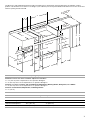
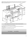
The dimension chart and illustration below include cutout dimensions and minimum spacing requirements for all built-in outdoor
products. The illustration is for reference. The design of your cabinet layout can be personalized, but the dimensions for the cutouts and
minimum spacing must be followed.
C
E
D
H
A
G
K
K
F
K
B
J
D
E
20⁵⁄₈" (52.4 cm)
1¹⁄₂"
(3.8 cm) min.
3" (7.6 cm) min.
to open hood
2¹⁄₂" (6.4 cm) min.
12" (30.5 cm) min.
to any accessory
12" min.
to any
accessory
20⁷⁄₈" (53.0 cm)
9¹⁄₈"
(23.2 cm)
5"
(12.7 cm) min.
C
M
L
K
K
Grills or
Refreshment Centers
Side
or
Sear
Burners
Warming
Drawer
Access Doors
Refrigerator
or
Ice Maker
Utility
or
Trash
Drawer
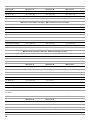
Minimum Spacing Requirement Between Cutouts - Dimension K
Between 2 or more sets of Access Doors adjacent to each other:
K = 14" (35.6 cm) when 2 adjacent doors are opened to 90 degrees
K = 8" (20.3 cm) when 1 of the adjacent doors is opened to 90 degrees
Between a set of Access Doors and a Trash Drawer, Utility Drawer, Warming Drawer, Refrigerator, or Ice Maker:
K = 8" (20.3 cm) when 1 of the adjacent doors is opened to 90 degrees
Between a Trash Drawer, Utility Drawer, or Warming Drawer:
K = 3" (7.6 cm)
Cabinet Height and Depth Dimensions
Dimension A Minimum Dimension B Minimum
With outdoor refrigerator 37" (94.0 cm) 26" (66.0 cm)
Grill with insulated jacket 36½" (92.7 cm) 27" (68.6 cm)
Grill without insulated jacket 35½" (90.2 cm) 26" (66.0 cm)

8
*Dimension L is the minimum mounting surface area around the opening for mounting the optional door or drawers.
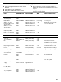
Cutout Dimensions - Built-in Grill
Grill Size Dimension C Dimension D Dimension E
27" (68.6 cm) 29⁵⁄₈" (75.2 cm) 10¾" (27.3 cm) 22⁷⁄₈" (58.1 cm)
36" (91.4 cm) 38⁵⁄₈" (98.1 cm) 10¾" (27.3 cm) 22⁷⁄₈" (58.1 cm)
48" (121.9 cm) 50⁵⁄₈" (128.6 cm) 10¾" (27.3 cm) 22⁷⁄₈" (58.1 cm)
Cutout Dimensions - Built-in Grill with Insulated Jacket
Grill Size Dimension C Dimension D Dimension E
27" (68.6 cm) 33" (83.8 cm) 11¾" (29.8 cm) 24" (61.0 cm)
36" (91.4 cm) 42" (106.7 cm) 11¾" (29.8 cm) 24" (61.0 cm)
48" (121.9 cm) 54" (137.2 cm) 11¾" (29.8 cm) 24" (61.0 cm)
Cutout Dimensions - Built-in Side Burner
Burner Position Dimension C Dimension D Dimension E
Front to Back 13½" (34.3 cm) 10¾" (27.3 cm) 22⁵⁄₈" (57.5 cm)
Side by Side 24½" (62.2 cm) 10¾" (27.3 cm) 16⁷⁄₈" (42.9 cm)
Cutout Dimensions - Built-in Sear Burner
Dimension C Dimension D Dimension E
13½" (34.3 cm) 10⁵⁄₈" (27.0 cm) 22¹¹⁄₁₆" (57.6 cm)
Cutout Dimensions - Built-in Refreshment Center
Dimension C Dimension D Dimension E
30½" (77.5 cm) 10¾" (27.3 cm) 23" (58.4 cm)
Cutout Dimensions - Built-in Access Doors
Door Size Dimension F Dimension L*
18" (45.7 cm) 16³⁄₁₆" (41.1 cm) 1½" (3.8 cm)
27" (68.6 cm) 25¹⁄₈" (63.8 cm) 1½" (3.8 cm)
30" (76.2 cm) 28¹⁄₈" (71.4 cm) 1½" (3.8 cm)
36" (91.4 cm) 34¹⁄₈" (86.7 cm) 1½" (3.8 cm)
48" (121.9 cm) 46¹⁄₈" (117.2 cm) 1½" (3.8 cm)
Cutout Dimensions - Outdoor Refrigerator
Dimension G Dimension H
24" (61.0 cm) 35¼" (89.5 cm)
Cutout Dimensions - Outdoor Ice Maker
Dimension G Dimension H
18" (45.7 cm) 34" (86.4 cm) min. to 34½" (87.6 cm) max.

9
*Dimension L is the minimum mounting surface area around the opening for mounting the optional door or drawers.
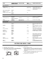
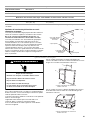
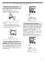
Built-in Outdoor Grill Enclosure Ventilation for LP Gas:
An enclosure for an LP gas fuel tank is to be ventilated by
openings at both the top and lower levels of the enclosure.
If converting to LP gas these vents are to be in the enclosure:
An enclosure for use with an LP gas fuel tank for built-in
installation is to have at least one ventilation opening on an
exposed exterior side located within 5" (12.7 cm) of the top is to
be a minimum of 20 in.
2
(129.0 cm
2
). One ventilation opening
within 1" (2.5 cm) of the bottom of the enclosure and the bottom
opening is to be a minimum of 10 in.
2
(64.5 cm
2
). All vent
openings are to be unobstructed. Every opening is to be a
minimum of ¹⁄₈" (0.32 cm) wide.
Electrical Requirements
If codes permit and a separate ground wire is used, it is
recommended that a qualified electrician determine that the
ground path is adequate.
Check with a qualified electrician if you are not sure whether the
grill is properly grounded.
A 120-volt, 60-Hz, AC-only, 15-amp, fused electrical supply is
required.
It is recommended that a separate circuit servicing only this grill
be provided.
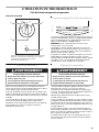
On freestanding models, the model/serial number rating plate is
located inside the grill cabinet on the right-hand cabinet side.
See the following illustration.
On built-in models, the model/serial number rating plate is
located on the right-hand side of the grill. See the following
illustration.
Cutout Dimensions - Built-in Warming Drawer
Warming Drawer Size Dimension J
24" (61.0 cm) 22½" (57.2 cm)
Cutout Dimensions - Built-in Utility Drawer and Built-in Trash Drawer
Dimension M Dimension L*
12¼" (31.1 cm) 1½" (3.8 cm)
10 in.
2
(64.5 cm
2
) min.
ventilation both sides
5" (12.7 cm) max.
1" (2.5 cm) max.
20 in.
2
(129.0 cm
2
) min.
ventilation both sides
5" (12.7 cm) max.
Electrical Shock Hazard
Plug into a grounded 3 prong outlet.
Do not remove ground prong.
Do not use an adapter.
Do not use an extension cord.
Failure to follow these instructions can result in death,
fire, or electrical shock.
WARNING
A. Model/serial number plate
A. Model/serial number plate
A
A

10
Recommended Ground Method
The outdoor grill, when installed, must be electrically grounded in
accordance with local codes or, in the absence of local codes,
with the National Electrical Code ANSI/NFPA 70, or Canadian
Electrical Code, CSA C22.1.
Copies of the standards listed above may be obtained from:
CSA International
8501 East Pleasant Valley Rd.
Cleveland, Ohio 44131-5575
National Fire Protection Association
One Batterymarch Park
Quincy, Massachusetts 02269
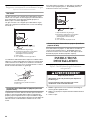
Gas Supply Requirements
Observe all governing codes and ordinances.
IMPORTANT: This installation must conform with all local codes
and ordinances. In the absence of local codes, installation must
conform with American National Standard, National Fuel Gas
Code ANSI Z223.1 - latest edition or CAN/CGA B149.1 - latest
edition.
IMPORTANT: Grill must be connected to a regulated gas supply.
Refer to the model/serial rating plate for information on the type
of gas that can be used. If this information does not agree with
the type of gas available, check with your local gas supplier.
Gas Conversion:
No attempt shall be made to convert the grill from the gas
specified on the model/serial rating plate for use with a different
gas type without consulting the serving gas supplier. The
conversion kits specified must be used.
Gas Pressure Regulator
The gas pressure regulator supplied with this grill must be used.
The inlet (supply) pressure to the regulator should be as follows
for proper operation:
LP Gas:
Operating pressure: 11" (27.9 cm) WCP
Inlet (supply) pressure: 11" to 14" (27.9 cm to 35.5 cm) WCP
Natural Gas:
Operating pressure: 4" (10.2 cm) WCP
Inlet (supply) pressure: 7" to 14" (17.8 cm to 35.5 cm) WCP
maximum.
Contact local gas supplier if you are not sure about the inlet
(supply) pressure.
Burner Requirements for High Altitude
Input ratings shown on the model//serial rating plate are for
elevations up to 2,000 ft (609.6 m).
For elevations above 2,000 ft (609.6 m), ratings are reduced at a
rate of 4% for each 1,000 ft (304.8 m) above sea level. Orifice
conversion is required. See “Assistance or Service” section to
order.
Gas Supply Line Pressure Testing
Testing above ½ psi (3.5 kPa) or 14" (35.5 cm) WCP (gauge):
The grill and its individual shutoff valve must be disconnected
from the gas supply piping system during any pressure testing of
that system at test pressures greater than ½ psig (3.5 kPa).
Testing below ½ psi (3.5 kPa) or 14" (35.5 cm) WCP (gauge) or
lower:
The grill must be isolated from the gas supply piping system by
closing its individual manual shutoff valve during any pressure
testing of the gas supply piping system at test pressures equal to
or less than ½ psig (3.5 kPa).
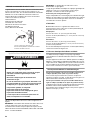
A. 3-prong ground plug
B. 3-prong polarized type outdoor outlet
C. Ground prong
A
B
C
WARNING
Explosion Hazard
Use a new CSA International approved “outdoor”
gas supply line.
Securely tighten all gas connections.
If connected to LP, have a qualified person make sure
gas pressure does not exceed 11” (28 cm) water
column.
Examples of a qualified person include:
licensed heating personnel,
authorized gas company personnel, and
authorized service personnel.
Failure to do so can result in death, explosion, or fire.

11
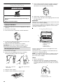
Gas Connection Requirements
Style 1 - Freestanding Outdoor Grills
20 lb LP Gas Fuel Tank
This grill is equipped for use with a 20 lb LP gas fuel tank (fuel
tank not supplied). A gas pressure regulator/hose assembly is
supplied.
It is also design-certified by CSA International for local LP gas
supply or for Natural gas with appropriate conversion.
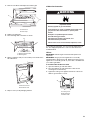
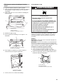
The 20 lb LP gas fuel tank must be mounted and secured.
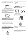
1. Open the 20 lb LP gas fuel tank drawer.
2. Place the 20 lb LP gas fuel tank bottom collar into the
mounting hole in the tank tray.
3. Tighten the locking screw against the bottom collar of the
20 lb LP gas fuel tank to secure.
4. Slide tank drawer back into the cabinet.
Local LP Gas Supply
IMPORTANT: The gas installation must conform with local
codes, or in the absence of local codes, with the National Fuel
Gas Code, ANSI Z223.1/NFPA 54 - latest edition. The qualified
LP gas technician shall provide the LP gas supply to the selected
grill location in accordance with the National Fuel Gas Code,
ANSI Z223.1/NFPA 54 and local codes.
Natural Gas Conversion
Conversion must be made by a qualified gas technician. The
qualified Natural gas technician shall provide the Natural gas
supply to the selected grill location in accordance with the
National Fuel Gas Code ANSI Z223.1/NFPA 54 - latest edition,
and local codes. For conversion to Natural gas, the Natural gas
conversion kit must be used.
IMPORTANT: The gas installation must conform with local
codes, or in the absence of local codes, with the National Fuel
Gas Code, ANSI Z223.1/NFPA 54 - latest edition.
To convert to Natural gas, the Natural Gas Conversion Kit Part
Number W10118098 must be used. Follow instructions included
with the kit.
A. Gas pressure regulator/hose assembly
A. Locking screw
B. Mounting hole
C. Bottom collar
A
A
B
C
A. Grill gas pipe
B. New ANSI Z21.54 certified gray hose
C. Rear of grill
D. To local LP gas supply
A. Grill gas pipe
B. New ANSI Z21.54 certified gray hose
C. Rear of grill
D. To Natural gas supply
A
B
C
D
A
B
C
D

12
Gas Connection Requirements
Style 2 - Built-In Outdoor Grills
Natural Gas
Built-in grill models are equipped for use with Natural gas. They
are design-certified by CSA International for LP (propane or
butane) gases with appropriate conversion.
Built-in models are set for Natural gas use and have a pressure
regulator with ½" female pipe threads.
The supply line shall be equipped with an approved shutoff valve.
This valve should be located in the same area as the grill and
should be in a location that allows ease of opening and closing.
Do not block access to the shutoff valve. The valve is for turning
on or shutting off gas to the grill.
LP Gas Conversion Using a Local LP Gas Supply
Conversion must be made by a qualified person. A qualified
Natural gas technician shall provide the LP gas supply to the
selected grill location in accordance with the National Fuel Gas
Code ANSI Z223.1/NFPA 54 - latest edition, and local codes.
To convert to LP gas, the LP Gas Conversion Kit Part Number
W10118099 must be used. Follow instructions included with kit.
LP Gas Conversion Using a 20 lb LP Gas Fuel Tank
To convert to LP gas, the LP Gas Conversion Kit Part Number
W10118099 must be used. Follow instructions included with kit.
A 20 lb LP gas fuel tank must be purchased separately.
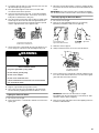
INSTALLATION
INSTRUCTIONS
Style 1 - Freestanding Outdoor Grill
Installation
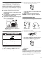
1. Unpack grill. Remove all packaging materials and remove grill
from wooden skid.
2. Move grill into desired outdoor location.
3. Open the hood.
Remove Packaging Material Inside the Grill
1. Cut the tiedowns holding the grates together.
2. Remove condiment shelf, warming shelf and grill grates from
inside the grill and remove packaging material.
A. Grill gas pipe
B. New CSA International approved
“outdoor” flexible gas supply line
C. Rear of grill
D. To Natural gas supply
A. Gas supply line
B. Shutoff valve “open” position
C. To grill
A
B
C
D
A
B
C
A. Grill gas pipe
B. New CSA International approved
“outdoor” flexible gas supply line
C. Rear of grill
D. To local LP gas supply
A
B
C
D
Excessive Weight Hazard
Use two or more people to move and install grill.
WARNING
Failure to do so can result in back or other injury.

13
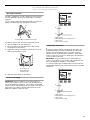
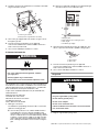
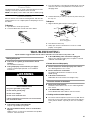
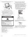
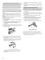
3. Remove foam block and wrap from inside the grill.
4. Replace the grill grates.
5. Place warming shelf on brackets as shown.
6. Attach condiment shelf (on some models) to the inside of the
left cabinet door.
7. Dispose of/recycle all packaging material.
Make Gas Connection
If converting to Natural gas, see conversion kit requirements in
the “Gas Supply Requirements” section. Follow instructions
included with kit.
LP Gas:
IMPORTANT: A 20 lb LP gas fuel tank must be purchased
separately.
IMPORTANT: The gas pressure regulator/hose assembly
supplied with the grill must be used. Replacement gas pressure
regulator/hose assembly specific to your model, is available from
your outdoor grill dealer.
To Install the 20 lb LP Gas Fuel Tank:
1. Open the 20 lb LP gas fuel tank drawer.
2. Place the 20 lb LP gas fuel tank bottom collar into the
mounting hole in the tank tray
3. Tighten the locking screw against the bottom collar of the
20 lb LP gas fuel tank to secure.
A. Foam block
B. Foam wrap
A. Warming shelf brackets
B. Warming shelf
A. Attachment holes
B. Condiment shelf
A
B
A
B
A
A
B
A. Locking screw
B. Mounting hole
C. Bottom collar
WARNING
Explosion Hazard
Securely tighten all gas connections.
If connected to LP, have a qualified person make sure
gas pressure does not exceed 11” (28 cm) water
column.
Examples of a qualified person include:
licensed heating personnel,
authorized gas company personnel, and
authorized service personnel.
Failure to do so can result in death, explosion, or fire.
A
B
C

14
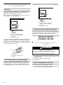
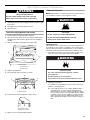
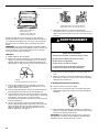
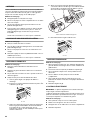
4. Screw the gas pressure regulator/hose assembly to the 20 lb
LP gas fuel tank as shown.
5. Turn on the gas supply. Wait a few minutes for gas to move
through the gas line.
6. Test all connections by brushing on an approved
noncorrosive leak-detection solution. Bubbles will show a
leak. Correct any leak found.
7. Go to “Check and Adjust the Burners” section.
If Converted to Natural Gas
This installation must conform with local codes and ordinances.
In the absence of local codes, installations must conform with
either the National Fuel Gas Code ANSI Z223.1, or CAN/CGA-
B149.1 Natural Gas and Propane installation code.
Copies of the standards listed above may be obtained from:
CSA International
8501 East Pleasant Valley Rd.
Cleveland, Ohio 44131-5575
National Fire Protection Association
One Batterymarch Park
Quincy, Massachusetts 02269
1. Make gas connections.
A combination of pipe fittings must be used to connect the
grill to the existing gas line.
■ If local codes permit, use an outdoor flexible stainless
steel tubing gas connector, design-certified by CSA
International, to connect the grill to the rigid gas supply
line. A ⁵⁄₈" diameter line is recommended. Using a wrench
to tighten, connect the gas supply to the grill. Use pipe-
joint compound on all non-flared male threads. Do not
kink or damage the flexible connector when moving the
grill.
■ Pipe-joint compounds suitable for use with Natural gas
must be used. Do not use TEFLON
®†
tape.
2. Open the manual shutoff valve in the gas supply line. The
valve is open when the handle is parallel to the gas pipe.
3. Test all connections by brushing on an approved
noncorrosive leak-detection solution. Bubbles will show a
leak. Correct any leak found.
4. Go to “Check and Adjust the Burners” section.
Plug in Grill
1. Plug into a grounded 3-prong outlet.
A. 20 lb LP gas fuel tank
B. Gas pressure regulator/hose assembly
A
B
WARNING
Explosion Hazard
Use a new CSA International approved “outdoor”
gas supply line.
Securely tighten all gas connections.
Failure to do so can result in death, explosion, or fire.
A. Grill gas pipe
B. New ANSI Z21.54 certified gray hose
C. Rear of grill
D. To Natural gas supply
A. Closed valve
B. Open valve
†®TEFLON is a registered trademark of E.I. Du Pont De Nemours and Company.
A
B
C
D
A
B
Electrical Shock Hazard
Plug into a grounded 3 prong outlet.
Do not remove ground prong.
Do not use an adapter.
Do not use an extension cord.
Failure to follow these instructions can result in death,
fire, or electrical shock.
WARNING

15
Style 2 - Built-in Outdoor Grill Installation
■ Unpack grill. Remove all packaging materials and remove grill
from carton.
■ Move grill close to desired outdoor location.
■ Open the hood.
Remove Packaging Material Inside the Grill
1. Cut the tiedowns holding the grates together.
2. Remove rotisserie skewer (on some models), warming shelf
and grill grates from inside the grill and remove packaging
material.
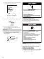
3. Remove foam block and wrap from inside the grill.
4. Replace the grill grates.
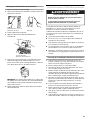
5. Place warming shelf on brackets as shown.
6. Install rotisserie mounting bracket using 2 screws.
7. Dispose of/recycle all packaging material.
Make Gas Connection
NOTE: If grill has been converted to LP gas, follow instructions in
“If Converting to LP Gas” at the end of this section.
Natural Gas Use
This installation must conform with local codes and ordinances.
In the absence of local codes, installations must conform with
either the National Fuel Gas Code ANSI Z223.1 - latest edition, or
CAN/CGA-B149.1 Natural Gas and Propane installation code.
1. Place grill into outdoor enclosure, but leave enough room in
back to connect to gas supply and electrical plug-in.
2. Make gas connections.
A combination of pipe fittings must be used to connect the
grill to the existing gas line.
■ If local codes permit, use an outdoor flexible stainless
steel tubing gas connector, design-certified by CSA
International, to connect the grill to the rigid gas supply
line. A ⁵⁄₈" diameter line is recommended. Using a wrench
to tighten, connect the gas supply to the grill. Use pipe-
joint compound on all non-flared male threads. Do not
kink or damage the flexible connector when moving the
grill.
A. Foam block
B. Foam wrap
A. Warming shelf brackets
B. Warming shelf
A. 2 bracket screws
B. Rotisserie bracket
Excessive Weight Hazard
Use two or more people to move and install grill.
WARNING
Failure to do so can result in back or other injury.
A
B
A
B
A
A B
WARNING
Fire Hazard
Do not use grill near combustible materials.
Do not store combustible materials near grill.
Doing so can result in death or fire.
WARNING
Explosion Hazard
Use a new CSA International approved “outdoor”
gas supply line.
Securely tighten all gas connections.
Failure to do so can result in death, explosion, or fire.

16
■ Pipe-joint compounds suitable for use with Natural gas
must be used. Do not use Teflon
®
tape.
3. Open the manual shutoff valve in the gas supply line. The
valve is open when the handle is parallel to the gas pipe.
4. Test all connections by brushing on an approved
noncorrosive leak-detection solution. Bubbles will show a
leak. Correct any leak found.
Plug in Grill
1. This built-in outdoor grill comes with a 5,000 mAmp power
transformer plug assembly for the grill lights and igniter. Plug
in the single-prong plug in the receptacle on the left
underside of the grill.
2. Plug into a grounded 3-prong outlet.
3. Gently slide grill completely into outdoor enclosure.
4. Now go to the “Check and Adjust the Burners” section.
If Converting to LP Gas
IMPORTANT: A 20 lb LP gas fuel tank must be purchased
separately.
IMPORTANT: The gas pressure regulator/hose assembly
supplied with the conversion kit must be used. Replacement gas
pressure regulator/hose assembly specific to your model, is
available from your outdoor grill dealer.
To Install the 20 lb LP Gas Fuel Tank:
1. Install the 20 lb LP gas fuel tank into the compartment below
the grill.
2. Screw the gas pressure regulator/hose assembly to the
20 lb LP gas fuel tank as shown.
A. Grill gas pipe
B. New CSA International approved
“outdoor” flexible gas supply line
C. Rear of grill
D. To Natural gas supply
A. Closed valve
B. Open valve
A. Single-prong plug
A
B
C
D
A
B
A
Electrical Shock Hazard
Plug into a grounded 3 prong outlet.
Do not remove ground prong.
Do not use an adapter.
Do not use an extension cord.
Failure to follow these instructions can result in death,
fire, or electrical shock.
WARNING
WARNING
Explosion Hazard
Use a new CSA International approved “outdoor”
gas supply line.
Securely tighten all gas connections.
If connected to LP, have a qualified person make sure
gas pressure does not exceed 11” (28 cm) water
column.
Examples of a qualified person include:
licensed heating personnel,
authorized gas company personnel, and
authorized service personnel.
Failure to do so can result in death, explosion, or fire.

17
3. Turn on the gas supply. Wait a few minutes for gas to move
through the gas line.
4. Test all connections by brushing on an approved
noncorrosive leak-detection solution. Bubbles will show a
leak. Correct any leak found.
5. Go to “Check and Adjust the Burners” section.
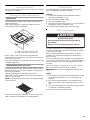
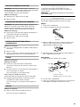
Check and Adjust the Burners
The burners are tested and factory-set for most efficient
operation. However, variations in gas supply and other conditions
may make minor adjustments to air shutter or low flame setting
necessary.
It is recommended that a qualified person make burner
adjustments.
NOTE: The rotisserie burner cannot be adjusted.
Checking and adjusting the grill burner flames requires removing
the grate and sear plates.
Burner Flame Characteristics
The flames of the grill burners and side burners (on some models)
should be blue and stable with no excessive noise or lifting (LP
gas flames will have a slightly yellow tip). A yellow flame indicates
not enough air. If flame is noisy or lifts away from the burner, there
is too much air. Some yellow tips on flames when the burner is
set to HI setting are acceptable as long as no carbon or soot
deposits appear.
Check that burners are not blocked by dirt, debris, insect nests,
etc. and clean as necessary. If they are clean, adjust air shutters
as needed.
IMPORTANT: Before adjusting air shutters, let burners cool
completely.
To Adjust:
1. Light grill using information in the “Outdoor Grill Use” section.
2. Observe flame to determine which burners need adjustment
and how the flame is acting.
3. Turn off the valve and wait until grill and burners cool
completely.
4. Remove grill grates and sear plates.
5. Remove the 2 screws that hold the burner in place. Remove
gas burner from the grill.
6. If flame is yellow (not enough air), turn air shutter adjustment
screw counterclockwise.
If flame is noisy or lifts away from burner (too much air), turn
air shutter adjustment screw clockwise.
Adjustment should be made clockwise or counterclockwise
from ¹⁄₈" (3.2 mm) to ¹⁄₄" (6.4 mm).
7. Replace gas burner, sear plates and grates.
8. Light grill using information in the “Outdoor Grill Use” section.
See “Burner Flame Characteristics.”
Low Flame Adjustment
If flame goes out on the “LO” setting, the low flame setting must
be adjusted.
1. Turn off the valve and wait until grill and burners are cool.
2. Remove grill grates and sear plates.
3. Light grill using information in the “Outdoor Grill Use” section.
4. Turn burner to its lowest setting and remove knob.
5. Hold valve stem with pliers and insert a small flat-blade
screwdriver into the shaft.
6. Watch the flame and slowly turn the screwdriver
counterclockwise.
7. Adjust flame to minimum stable flame.
8. Replace the control knob and turn off the burner.
9. Repeat steps 3 through 8 for each burner if needed.
10. Replace the sear plates and grates after the burners have
cooled.
A. 20 lb LP gas fuel tank
B. Gas pressure regulator/hose assembly
A
B
A. 2 screws
A. Air shutter adjustment screw
A. Valve stem
B. Small flat-blade screwdriver
C. Pliers
A
A
A
B
C

18
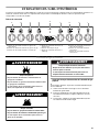
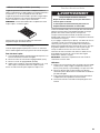
OUTDOOR GRILL USE
This manual covers several different models. The grill you have purchased may have some or all of the features listed. The locations and
appearances of the features shown here may not match those of your model.
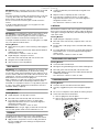
Control Panel
Using Your Outdoor Grill
Inspect the LP Gas Fuel Tank Supply Hose
Inspect the gas pressure regulator/hose assembly before each
use.
1. Open the right-hand drawer and slide 20 lb LP gas fuel tank
out.
2. Inspect the entire gas pressure regulator/hose assembly for
cuts, abrasions, or excessive wear.
3. If necessary, replace the gas pressure regulator/hose
assembly before using the grill.
Contact the dealer and use only replacement hoses specified for
use with the grill.
A. Left rotisserie burner control knob
B. Left grill burner control knob
C. Center grill burner control knob
D. Right grill burner control knob
E. Electronic grill display
F. Sear burner control knob
G. Right rotisserie burner control knob
H. Front side burner control knob
I. Rear side burner control knob
A
B
C D
E
F
G
H I
LIGHTS
WARNING
Explosion Hazard
Do not store fuel tank in a garage or indoors.
Do not store grill with fuel tank in a garage or indoors.
Failure to follow these instructions can result in death,
explosion, or fire.
WARNING
Fire Hazard
Do not use grill near combustible materials.
Do not store combustible materials near grill.
Doing so can result in death or fire.
A. Gas pressure regulator/hose assembly
WARNING
Food Poisoning Hazard
Do not let food sit for more than one hour before or
after cooking.
Doing so can result in food poisoning or sickness.
A

19
Prepare the Gas Supply
1. Open the hood completely. Do not light burners with the hood
closed.
2. Make sure control knobs are turned to OFF. The drip pan
must be in place and pushed all the way to the back.
Turn the Gas Supply On
1. For freestanding outdoor grills using a 20 lb LP gas fuel tank:
Slowly open the tank valve.
NOTE: If flow limiting device activates, your grill may not
light. If your grill does light, the flames will be low and will not
heat properly. Turn tank valve and all control knobs off and
wait 30 seconds. After shutting off the tank, very slowly open
tank valve and wait 5 seconds before lighting.
2. For outdoor grills using gas supply source other than 20 lb LP
gas fuel tank:
Open the manual shutoff valve in the gas supply line. The
valve is open when the handle is parallel to the gas pipe.
Lighting the Grill and Infrared Sear Burner
1. Do not lean over the grill.
2. Select the burner you want to light. Push in and turn the grill
burner control knob to LITE/HI, while continuing to hold it in.
3. You will see the igniter glow. When burner is lit, release the
knob. Turn knob to desired setting.
4. Repeat for each of the other burners as needed.
IMPORTANT: If burner does not light immediately, turn the
burner knob to OFF and wait 5 minutes before relighting.
Manually Lighting Main Grill and Infrared Sear Burners
1. Do not lean over the grill.
2. Remove the manual lighting extension (see following
illustration) and attach a match to the split ring.
3. Strike the match to light it.
4. Guide the lit match between the grill grate and one of the
slots in the sear plate.
5. Push in and turn the burner knob to LITE/HI for the burner
closest to the lit match. The burner will light immediately.
When burner is lit, turn knob to desired setting.
6. Repeat steps 2 through 5 for each main burner.
7. Remove match and replace manual lighting extension inside
the cabinet drawer.
IMPORTANT:
If burner does not light immediately, turn the burner knob to OFF
and wait 5 minutes before relighting.
If any burners do not light after attempting to light them manually,
contact the KitchenAid Customer eXperience Center. See the
“Assistance or Service” section.
Using Your Infrared Sear Burner
Infrared grilling produces intense heat which quickly sears the
meat. Searing locks in flavor and juices while allowing the outer
surface to absorb smoke and food aroma that is produced as
grease and drippings are vaporized by the burner. The result is a
crisp, flavorful outside with a tender, juicy inside.
■ Preheat the infrared sear burner for 5 minutes.
■ Ensure that meats are fully thawed and that all excess fat is
trimmed away prior to grilling.
■ Leave the burner set to HI when placing food on the grill to
sear.
■ Use the sear burner to sear meat 1 to 2 minutes on each side,
then move the meat to the main grill cooking surface to finish
grilling to the desired doneness.
A. Drip pan
Freestanding grills - right-
hand cabinet door
Built-in grills - right-hand side
flange
A
NOTE: View is shown with grates removed. Grates are
to be in place when using the infrared sear burner.

20
Using Your Side Burner
Lighting the Side Burner
1. Remove the side burner cover. Do not light burners with the
cover on.
2. Do not lean over the grill.
3. Push in and turn the control knob to LITE/HI and hold in.
4. You will see the igniter glow. When burner is lit, release the
knob. Turn knob to desired setting.
5. Repeat for each of the other burners as needed.
IMPORTANT: If burner does not light immediately, turn the
burner knob to OFF and wait 5 minutes before relighting.
Manually lighting the side burner
1. Do not lean over the grill.
2. Remove the manual lighting extension (see following
illustration) and attach a match to the split ring.
3. Strike the match to light it.
4. Guide the match to the burner you wish to light.
5. Push in and turn the burner knob to LITE/HI for the burner
closest to the lit match. The burner will light immediately.
When burner is lit, turn knob to desired setting.
6. Repeat steps 2 through 5 for each burner.
7. Remove match and replace manual lighting extension inside
the cabinet drawer.
IMPORTANT:
If burner does not light immediately, turn the burner knob to OFF
and wait 5 minutes before relighting.
If any burners do not light after attempting to light them manually,
contact the KitchenAid Customer eXperience Center. See the
“Assistance or Service” section.
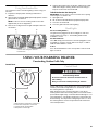
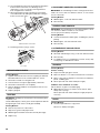
Using Your Rotisserie
For best cooking results, do not use main grill burners when
using the rotisserie.
The rotisserie system is designed to cook food from the rear
using intense, searing infrared heat.
NOTE: To avoid product damage when not using the rotisserie,
remove motor and store indoors. Remove spit rod and forks.
Store out of reach of children.
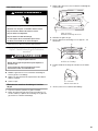
To Use:
1. Remove warming shelf.
2. Mount rotisserie motor on the grill’s mounting bracket.
Position it securely into support bracket slots. Plug single-
prong plug 500 mAmp transformer assembly into rotisserie
motor.
Portable grills - right-hand
cabinet drawer
Built-in grills - right-hand side
flange
WARNING
Burn Hazard
Do not let the burner flame extend beyond the edge of
the pan.
Doing so can result in burns.
A. Rotisserie motor
B. Spit rod
C.Rotisserie fork
D. Rotisserie burner
A. Rotisserie motor
B. Single-prong power cord
A
B
C
D
A
B
La page est en cours de chargement...
La page est en cours de chargement...
La page est en cours de chargement...
La page est en cours de chargement...
La page est en cours de chargement...
La page est en cours de chargement...
La page est en cours de chargement...
La page est en cours de chargement...
La page est en cours de chargement...
La page est en cours de chargement...
La page est en cours de chargement...
La page est en cours de chargement...
La page est en cours de chargement...
La page est en cours de chargement...
La page est en cours de chargement...
La page est en cours de chargement...
La page est en cours de chargement...
La page est en cours de chargement...
La page est en cours de chargement...
La page est en cours de chargement...
La page est en cours de chargement...
La page est en cours de chargement...
La page est en cours de chargement...
La page est en cours de chargement...
La page est en cours de chargement...
La page est en cours de chargement...
La page est en cours de chargement...
La page est en cours de chargement...
La page est en cours de chargement...
La page est en cours de chargement...
La page est en cours de chargement...
La page est en cours de chargement...
La page est en cours de chargement...
La page est en cours de chargement...
La page est en cours de chargement...
La page est en cours de chargement...
La page est en cours de chargement...
La page est en cours de chargement...
La page est en cours de chargement...
La page est en cours de chargement...
La page est en cours de chargement...
La page est en cours de chargement...
La page est en cours de chargement...
La page est en cours de chargement...
La page est en cours de chargement...
La page est en cours de chargement...
La page est en cours de chargement...
La page est en cours de chargement...
-
 1
1
-
 2
2
-
 3
3
-
 4
4
-
 5
5
-
 6
6
-
 7
7
-
 8
8
-
 9
9
-
 10
10
-
 11
11
-
 12
12
-
 13
13
-
 14
14
-
 15
15
-
 16
16
-
 17
17
-
 18
18
-
 19
19
-
 20
20
-
 21
21
-
 22
22
-
 23
23
-
 24
24
-
 25
25
-
 26
26
-
 27
27
-
 28
28
-
 29
29
-
 30
30
-
 31
31
-
 32
32
-
 33
33
-
 34
34
-
 35
35
-
 36
36
-
 37
37
-
 38
38
-
 39
39
-
 40
40
-
 41
41
-
 42
42
-
 43
43
-
 44
44
-
 45
45
-
 46
46
-
 47
47
-
 48
48
-
 49
49
-
 50
50
-
 51
51
-
 52
52
-
 53
53
-
 54
54
-
 55
55
-
 56
56
-
 57
57
-
 58
58
-
 59
59
-
 60
60
-
 61
61
-
 62
62
-
 63
63
-
 64
64
-
 65
65
-
 66
66
-
 67
67
-
 68
68


KitchenAid KBNU367TSS0 Le manuel du propriétaire
- Catégorie
- Barbecues
- Taper
- Le manuel du propriétaire
- Ce manuel convient également à
dans d''autres langues
Documents connexes
-
KitchenAid KBNU367T Manuel utilisateur
-
-
-
-
-
KitchenAid KFRU488TSS00 Le manuel du propriétaire
-
-
-
-
