Paslode F325R Compact Framing Nailer Le manuel du propriétaire
- Catégorie
- Outils électroportatifs
- Taper
- Le manuel du propriétaire

1
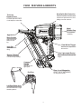
MODEL F325R
Framing Nailer
IMPORTANT!
DO NOT DESTROY
It is the customers responsibility to have all
operators and service personnel read and
understand this manual.
OPERATING MANUAL AND
SCHEMATIC
513057-2
10/14
PRINTED IN U.S.A.
© 2014, Illinois Tool Works Inc.

2
INTRODUCTION
TOOL AND FASTENER SPECIFICATIONS ................................................................. 3
SAFETY INSTR
UCTIONS ............................................................................................
4
TOOL INSTALLATION AND OPERATION ................................................................ 5-6
AIR SYSTEMS ............................................................................................................. 7-8
FEATURES AND BENEFITS .......................................................................................... 9
EXPLODED VIEW AND SPARE PARTS LIST ....................................................... 10-11
MAINTENANCE ........................................................................................................ 12-13
TROUBLESHOOTING .................................................................................................. 14
WARRANTY .................................................................................................................. 15
ACCESSORIES ........................................................................................................... 16
applications. This tool will deliver
dependable performance
when
used according
to the manufactures guidelines.
Please study this manual including
the
safety instructions
to fully understand the operation of this tool.
The Paslode F325R remodeling framing nailer is a quality-built tool designed for use in
residential framing
®

3
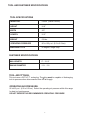
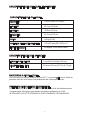
TOOL SPECIFICATIONS
MODEL NO. F325R (Part# 513000)
HEIGHT
12.9”
WIDTH
4.3"
LENGTH
12.3"
WEIGHT 5.9 lbs.
OPERATING PRESSURE 90 to 120 p.s.i. (6.2 to 8.3 bar)
FASTENER SPECIFICATIONS
TOOL AIR FITTINGS:
This tool uses a 3/8” N.P.T. male plug. The
tting must be capable of discharging
tool air pressure when disconnected from the air supply.
OPERATING AIR PRESSURE:
90 to120 p.s.i. (6.2 to 8.3 bar). Select the operating air pressure within this range
for best tool performance.
DO NOT EXCEED THIS RECOMMENDED OPERATING PRESSURE.
NAIL LENGTH
2” - 3-1/4"
SHANK DIAMETER .113 - .131
TOOL AND FASTENER SPECIFICATIONS
MAGAZINE TYPE 30 degree, Single Strip

4
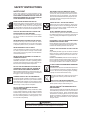
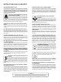
WARNING
Failure to follow any of the above instructions could result in severe personal
injury to tool user and bystanders or cause damage to tool and property.
SAFETY INSTRUCTIONS
SAFETY FIRST
WEAR EYE AND HEARING PROTECTION
Always wear hearing and eye protection devices, that
conform to ANSI Z87.1 requirements, when operating
or working in the vicinity of a tool. As an employer you
are responsible for enforcing the use of eye protection.
Wear hard hats in environments that require their use.
THE TOOL MUST BE USED ONLY FOR THE PUR-
POSE FOR WHICH IT WAS DESIGNED
any way or use the tool as a hammer to knock material
into place.
NEVER ENGAGE IN HORSEPLAY WITH THE TOOL
The tool is not a toy so do not use it like one. Never
engage in horseplay with the tool or point it at yourself
or any other person, even if you think it is not loaded.
NEVER ASSUME THE TOOL IS EMPTY
Check the magazine for fasteners that may be left in the
tool. Even if you think the tool is empty or disconnected,
never point it at anyone or yourself. Unseen fasteners
NEVER CLAMP THE TRIGGER IN A LOCKED OR
OPERATING POSITION
The trigger of the tool must never be tampered with,
disabled or clamped in a locked or operating position
since this will cause the tool to drive a fastener any
time the work contacting element depressed.
DO NOT LOAD FASTENERS WITH THE AIR LINE
CONNECTED, OR WITH THE TOOL TRIGGER OR
WORK CONTACTING ELEMENT DEPRESSED
When loading fasteners into the tool be sure you
disconnect the air line and that you do not depress
the trigger or work contacting element.
OPERATE THE TOOL ONLY ON A WORKPIECE
The tool should be operated only when it is in contact
with the workpiece. Even then you should be careful
when fastening thin material or working near the edges
and corners of the workpiece since the fasteners may
drive through or away from the workpiece.
DO NOT DISABLE OR REMOVE THE WORK
CONTACTING ELEMENT
This tool is equipped with a safety mechanism, called
a work contacting element, to help prevent accidental
the work contacting element. Do not use the tool unless
the work contacting element is working properly. The
DISCONNECT THE TOOL WHEN NOT IN USE
Always disconnect the tool from the air line when it
is not in use, when you leave the work area or when
moving the tool to a new location. The tool must
never be left unattended because people who are
not familiar with the tool might handle it and injure
themselves or others.
CARRY THE TOOL ONLY BY THE HANDLE
Always carry the tool by the handle only. Never carry
the tool by the air hose or with the trigger depressed
since you could drive a fastener unintentionally and
injure yourself or someone else.
DO NOT WEAKEN THE TOOL HOUSING
The tool housing is a pressure vessel and should never
be weakened by having your name, area of
work or anything else stamped or engraved into its
surface.
DISCONNECT THE TOOL WHEN PERFORMING
REPAIRS AND CLEARING JAMS
Never attempt to clear a jam or repair a tool unless
you have disconnected the tool from the air line and
removed all remaining fasteners from the tool.
ALWAYS USE THE PROPER FITTING FOR THE
TOOL
Only MALE pneumatic type air connectors should be
to the tool, so that high pressure air in the tool is
vented to atmosphere as soon as the air line is dis-
connected.
NEVER install FEMALE quick disconnect couplings on
the tool. Female couplings will trap high pressure air in
the tool when the air line is disconnected, leaving the
tool charged and able to drive at least one fastener.
DO NOT EXCEED THE MAXIMUM RECOMMENDED
AIR PRESSURE
.erusserp ria dednemmocer eht ta ylno loot eht etarepO
Do not the air pressure marked on
the tool. Be sure the air pressure gauge is operating
properly and check it at least twice a day.
Never use any bottled air or gases such as to
operate the tool since they could cause the tool
to
INSPECT TOOL FOR PROPER OPERATION
.deriuqer sa etacirbul dna yliad tsael ta loot eht naelC
Never operate a dirty or malfunctioning tool.
USE ONLY PASLODE RECOMMENDED PARTS
AND FASTENERS
Use only parts and fasteners designed and
recommended by Paslode for use in the tool and for
and for work to be done. Using unauthorized parts
and fasteners or modifying the tool in any way creates
dangerous situations. Replace all missing warning
labels---refer to tool schematic for correct placement
and part number.
These safety instructions provide information neces-
sary for safe operation of Paslode framing tools. DO
NOT ATTEMPT TO OPERATE THE TOOL UNTIL YOU
READ AND UNDERSTAND ALL SAFETY PRECAU-
TIONS AND MANUAL INSTRUCTIONS.
®
®
®

5
TOOL INSTALLATION
Your Paslode tool comes ready for immediate use
and can be installed by following these steps:
1. SAFETY - All tool operators and their immediate
supervisors must become familiar with the operator
safety instructions before operating the tool. The
instructions are on page 4 of this manual.
2. Included with each tool are one copy of this
Safety and Maintenance manual and one copy of
the Tool Schematic. Keep these publications for
future reference. An ownership registration card is
also included. This card must be completed and
returned to Paslode immediately to register your
ownership.
3. The plastic cap in the air inlet of the tool must be
removed before the male fitting is installed. The t-
ting must be a male pneumatic type that discharges
the air from the tool when the air line is disconnected.
4. Install a fi
lter/regulator/lubricator unit, with a
gauge as close as practical to the tool, preferably
within ten feet. Refer to the Air Systems section of
this manual for air hose requirements and lengths.
In general, no other special installation is required.
5. If the operator is working at a bench or table,
it is usually best to run the air line underneath the
bench. A small tray under the benchtop can hold
the fastener supply and the tool when not in use.
6. If this tool does not work when it is first connect-
ed, do not try to make repairs. Call your Paslode
representative immediately.
TOOL OPERATION
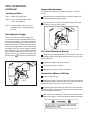
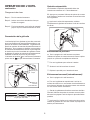
Depth of Drive Adjustment
(On tools equipped with this feature)
2. The depth of drive adjustment is made by turn-
ing the thumbwheel on the work contact element.
If the tool is overdriving (the fastener head is
driven below the work surface), the work con-
tact element should be moved downward. If
the fasteners stand up (the head not flush with
the surface), the work contact element should
be moved up.
Adjust the work contact element until the fas-
tener head depth meets job requirements.
WORK
CONTACT
ELEMENT
ROTATE
THUMBWHEEL
IN EITHER
DIRECTION
®
®
®
The depth of drive adjustment can be adjusted
two ways.
1. One way is to adjust the air supply to provide
mended operating pressure of 120 PSI.
enough drive to meet the proper depth for the
application without exceeding manufactures recom-
Tools with a Depth of Drive
Adjustment

6
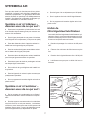
Sequential Operation
The sequential operating kit prevents succesive or "bounce"
driving.
Depress the work contacting element and hold it against the
work surface before pulling the trigger.
After each fastener is driven, completely release the trigger
and lift the tool from the work surface.
Precision Placement Driving
pletely depressed.
Squeeze the trigger to drive the fastener.
Lift the tool from the workpiece.
Repeat the procedure for the next fastener.
Successive (Bounce) Driving
Squeeze the trigger and move the tool along the workpiece
with a bouncing motion, depressing the work contacting element
at the points where you want to insert a fastener.
Keep the trigger depressed and continue to bounce the work
contacing element against the workpiece, positioning the tool
above as carefully as possible.
When the desired number of fasteners have been driven,
release the tool trigger to avoid unintentional fastener discharge.
TOOL OPERATION -
continued
Loading of Nails
rear of the magazine.
magazine until it is engaged behind
the nails.
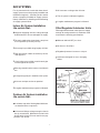
Switching the Trigger
The tool is manufactured with a trigger that
can be switched from sequential operation to a
bounce drive operation. The trigger is placed in
the sequential operating position when the tool
was manufactured. To switch the trigger to the
and trigger pivot pin from the trigger assembly.
Move the trigger to the bounce operation position
postion indicator on the tool should now be
pointing to the as shown in the illustration.
Bounce drive
position
indicator
Sequential
drive position

7
AIR SYSTEMS
For air-powered tools to work their best, the air
supply system must be properly installed and
maintained regularly. A drawing in this section
shows a properly installed air supply system.
Handy checklists for installing and maintaining
air supply systems follow.
Indoor Air System Installation
-Be certain that:
All pipes supplying air have a large enough
inside diameter to ensure adequate air supply.
The main supply pipe slopes down, away from
the compressor (1/16 inch per foot).
Air storage is provided along lengthy air lines.
Pipe line branch outlets are at the top of the
main pipe line.
Cutoff valves are provided at each branch pipe
line throughout the system.
Water legs extend from the bottom of each branch
line.
A refrigerant-type dryer is installed on the system.
Air hoses are kept as short as practical.
A regular maintenance program is followed.
Outdoor Air System Installation
-Be certain that:
are installed at the compressor.
inch ID with 1/2 inch ID hose used for any ap-
plication over 25 feet.
Air hoses are not longer than 150 feet.
The air system is lubricated regularly.
A regular maintenance program is followed.
Filter/Regulator/Lubricator Units
Filter/regulator/lubricator units that can supply
enough air and protection for Paslode
Lubricators designed for low or changing
®
tools

8
AIR SYSTEMS - Continued
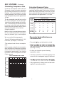
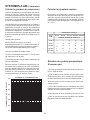
Calculating Compressor Size
The air consumption chart will help you find
the
correct compressor size for your appli-
cation that will quickly replenish tool air pres-
sure.
To use the chart you will need to know
how many tools will be used and approxi-
mately how many fasteners will be driven
each
minute by each tool on the line.
Number of tools X average fasteners/minute/
tool X 1.2 (safety factor) X air consumption
(scfm) @ pressure* (psi) = scfm required.
We can use the following example:
10 tools X 30 fasteners/minute/tool X 1.2 X
0.051scfm* (@100psi) = 18.36 scfm.
*This number is found in the air consumption
chart.
In this example, using the air consumption
chart we find that a compressor providing
at least 19 scfm of air is required. Because
in compressors approximately 1 hp is required
to produce 4 scfm, a compressor of at least
5 hp is required.
Calculated Required Piping
For example, given a 20 hp electric compressor
supplying approximately 80 cfm of air at 120 psi
and a main supply pipe length of 350 feet, we see
by the table the minimum main pipe inside diam-
eter required for this application is 1-1/4 inch.
Pneumatic System Maintenance
- Be certain that:
Pneumatic ttings are tight and do not leak.
and ensure that automatic draining systems are
operating correctly.
especially in winter.
ensure it has an adequate supply of lubricant.
regulator is operating properly.
Using the equation:
VOLUME
OF AIR
(CFM)
LENGTH OF RUN (FT.)
NOMINAL PIPE DIAMETER (IN.)
50-200 290-500 500-1000 1000-2500 2500-5000
30-60
60-100
100-200
200-500
500-1000
1 1 1¼ 1½ 1½
1 1¼ 1¼ 2 2
1¼ 1½ 2 2¼ 2½
2 2½ 3 3½ 3½
2½ 3 3½ 4 4½
Use the air consumption chart in the Tool
Schematic for each tool when calculating
the operating requirements for the tools.
Paslode tools are designed to operate
efficently between 90 and 120 psi and should
never be operated at pressure greater than
120 psi.
®
60 70 80 90 100 110 120
AIR CONSUMPTION-SCFM/FASTENER
.060
.055
.050
.040
.035
AIR PRESSURE-PSIG
.030
REFER
TO CHA
R
T
IN TOOL
SCHEMATIC
AIR CONSUMPTION CHART

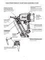
9
Metal
Exhaust Cap
For maximun
durability.
Tool-Less
Provides precise control
of nail depth (on other side)
Compact
Design
Able to get into
tight spots
Bypass Follower
For fast 2-step loading.
Lock Out
Eliminates blank
Holds 1 strip or appoximately
41 nails
plus lockout.
Aggressive
Work Contact
Grabs the wood
when toe nail-
ing.
Dual Mode
Trigger
Switches from sequential to
Ultra Lightweight Design
Easy to manuever with less arm
fatigue.
F325R FEATURES & BENEFITS
Left/Right Rafter Hook
Accommodates left-or right-
handed operators.
End Plug
Nonslip No-Mar Protection
Prevents scratches of interior work
sliding on smooth surfaces
surfaces and prevents the tool from
Depth of Drive
Rear Load Magazine

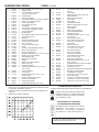
10
1
511444 1 Air Deflector 2
511847 4 3
408302 6
S.H.C.S. #10-24 x 1”
4
513003 1 Top Cap 5
511413 1 Top Cap Gasket 6
513042 1 Valve Spring, Main 7
201756 1 O-Ring, Post 8
202398 1 O-Ring, Cap 9
511960 1 Poppet 10
511876
1 O-Ring, Internal Poppet11
539676
1 O-Ring, External Poppet12
511719 1 Exhaust Seal13
1011802 1 14
511799 1 S.H.C.S.1/4-28 x 1-9/16” 15
511411 1 Piston “K” Seal16
17
18
511409 1 Sleeve
19
502310 1 Check Valve Band
20
511970 1 O-Ring, Inner Flange
21
511407 1 Sleeve Flange
22
511447 1 O-Ring, Outer Flange
23
513076 1
Bumper
24
511585 1 Driver Blade Seal
25
502055 1 Compression Spring
26
502050 1 Detent Body
27
404361 1 Roll Pin 1/8 x 1/2”
28
502046 1 Upper Work Contact Element
29
502049 1 Ball Detent
30
502061 1 Compression Spring
31
502036 1 Thumbwheel Assembly
32
502047 1 Lower Work Contact Element
33
513002 1 Housing with Grip
34
502058 2 Housing Label
35
36
502333 2 Roll Pin 1/8 x 1-1/2”
37
502324 1 Trigger Pin
38
502042 1 O-Ring
511713 1 Roll Pin 3/16 x 1-3/8”
40
502033 1 Work Contact Element Guide
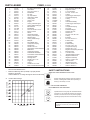
PARTS LEGEND
F325R
,
513000
* Denotes Normal Wear Items.
** Make sure Warning Label (513092) is properly affixed.
Replace if necessary.
Label available at no charge through the Service Parts Dept.
Always wear hearing protection and eye protection
devices, including side shields when operating or
working in the vicinity of a tool.
Operate the tool using only the recommended air
pressure. Do not exceed the maximum air pressure
marked on the tool. Be sure the air pressure gauge is
operating properly and check it at least twice a day.
41
513066 1 Nose Assembly with Isolators
42
002187 4 1/4” Lockwasher
43
511714 4 S.H.C.S. 1/4-20 x 7/8”
44
502014 2 Magazine Isolator
45
197913 1 O-Ring
46
502044 1 Upper Trigger Valve Spool
47
502059 1 Compression Spring
48
196345 1 O-Ring
49
1015358 1 O-Ring
50
511446 1 Valve Pin Assembly
51
502043 1 Lower Trigger Valve Spool
52
092747 1 O-Ring
53
502060 1 Compression Spring
54
502040 1 Trip Lever
55
511145 1 Dual ModeTrigger
56
091866 1 Roll Pin 1/8 x 3/4”
57
502332 1 Rafter Hook
58
502345 1 S.H.C.S. 5/16-18 x 5/8”
59
402963 1 O-Ring
60
513005 1 End Plug
61
502336 2 S.H.C.S. #10-24 x 1”
62
502019 1 Follower Claw
63
511196 1 Negator Drum/Spring Assembly
64
65
502021 1 Lockout Bar
66
511118 1 Follower Body
67
500627 1 S.H.C.S. 8-32 x 1/2”
68
502020 1 Compression Spring
69
513092 1 Warning Label
70
2 Lock Nut 1/4-20
71
442681
2 Magazine Wear Rods
72
502193 1 Actuation Settings Label
73
513016
1 Magazine Assembly
74
513059
2 B.H.C.S. 1/4-20 x 3/4”
75
502017
2 Stop Nut 8-32
76
404325
1 Magazine End Cap502029
1 B.H.C.S. #8-32 x 1/2”
Never use any bottled air or gases such as oxygen
to operate the tool since they could cause the tool
to explode.
SAFETY INSTRUCTIONS
WEAR EYE AND HEARING PROTECTION
**
*
*
*
*
*
*
*
*
*
*
*
*
*
*
AIR CONSUMPTION - SCF/FASTENER
AIR PRESSURE - PSIG
DO NOT EXCEED MAXIMUM
RECOMMENDED AIR PRESSURE
.090
SCF
Denotes New Change
Flat Washer
Flat Washer
*
*
*
*
•
502031
502038
511943 1 Nut, Nylon-insert 1/4”-28
403796 1 Roll Pin 1/8 x 1-1/4”
1 B.H.C.S. #8-32 x 1”
39

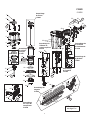
11
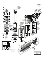
1
2
3
4
5
6
7
8
9
12
10
11
13
14
15
4
16
17
Note: Install check band
with thick side down.
# Torque Values
IN-LBS
Follower Body
Assembly
513068
Magazine
Assembly
513059
Piston
Assembly
513008
Trigger
Valve
Assembly
511460
Trigger
Assembly
513061
120
#
65
#
200
#
15
#
120
#
20
#
70
#
130
#
Nose
Assembly
513066
Upper WCE
Assembly
502734
Valve
Assembly
511465
Main
F325R
513000
18
19
20
21
22
23
24
25
26
27
28
29
30
31
32
33
34
35
36
37
38
39
40
41
42
43
44
45
48
46
47
49
50
51
52
53
54
55
56
57
58
59
60
61
65
64
63
62
66
67
68
70
69
71
72
73
74
75
76

12
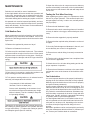
MAINTENANCE
Air-operated tools must be inspected periodically, and worn
or broken parts must be replaced to keep the tool operating
safely and ef
fi
ciently. Also the items on the maintenance
chart must be checked often.
Cold Weather Care
When temperatures are below freezing, tools should be
kept warm by any convenient, safe method. If this is not
possible, the following procedure should be used to warm
up the tools.
Reduce the regulated air pressure to 30 psi.
Remove all fasteners from the tool.
Collect an air line and blank fi
re the tool. The reduced
air pressure will be enough to free-fire the tool. Slow speed
operation tends to warm up the moving parts. Slowing up
the piston helps the bumper and the O-rings to become
springy.
Once the tool is warmed up, readjust the regulator to the
proper working pressure and reload the tool.
Tool operators working outdoors or in unheated areas in
extremely cold temperatures should also:
Use pneumatic oil with antifreeze in the
lubricator, Part No. 219090 (8oz.)
Once a week, depending on the amount of tool
use, take the tool apart and wash away any sludge
with tool cleaner ( Part No. 219348) to keep the
tool operating efficently.
Cleaning the air-operated tools with solvents removes the
thin coating of grease applied to the cylinder wall and
O-rings at the factory. To replace this coating of grease,
use Chemplex grease (Part No. 403734).
Open the drain on the air compressor tank to drain any
moisture at least daily in extremely cold or humid weather.
A few ounces of anti-freeze in the tank will keep the air
free of frost.
Testing the Tool After Servicing
After replacing any part or parts, it is important to check
the tool for proper operation. This ensures that the tool
was put together correctly, is safe to use, and will perform
the job properly.
Ensure that all hardware is tight.
Ensure that the work contacting element is installed
correctly in relation to the trigger, and that both parts move
freely.
Ensure that the magazine is properly attached.
Ensure that the required safety information on the tool
is legible.
Use only Paslode®
approved fasteners in the tool, and
ensure that they are correct for the application.
Ensure that a male air fitting is securely connected to
the tool.
Test the tool by driving fasteners into a workpiece iden-
tical to the tool's application.
Check the tool for air leaks during testing and for the
proper sequence of operation.
Ensure that all fasteners are driven to the same depth
and that the crown of the fastener is flush with the work-
piece.
Tool Lubrication
It is most important that the tool be properly lubricated by
keeping the air line lubricator fi
lled and correctly adjusted.
Without proper lubrication the tool will not work properly
and parts will wear prematurely.
Use the proper lubricant in the air line lubricator. The
lubricator should be of low air flow or changing air flow
type, and should be kept filled to the correct level. Use
harm the rubber compounds in the tools O-rings and other
rubber parts. Part No. 403720 is a pneumatic lubricanting
oil specially made for pneumatic applications.
If a filter/regulator/lubricator is not installed on the air sys-
tem, air operated tools should be lubricated at least once
a day with 6 to 20 drops of oil, depending on the work en-
vironment, directly through the male fitting in the tool
housing.
Most minor problems can be resolved quickly and easily
using the maintenance table that follows. If problems per-
sist, contact your Paslode® dealer for assistance.
Paslode tools are built for ease of maintenance.
A few simple details will assure trouble-free operation and
long tool life. Anyone who uses or maintains the tool must
read the safety and maintenance instructions. Study the
schematic drawing before starting any repairs on the tool.
®

13
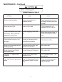
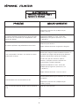
MAINTENANCE - Continued
Drain air line filter(daily).
Keep lubricator
filled.
Clean filter element-then blow
air through filter in direction
opposite to normal flow.
Check that all screws on tool
are tight.
Keep work contacting elelment
working properly.
Keep magazine and feeder
mechanism clean.
Lubricate "O" rings that are
replaced.
Use only Paslode replacement
parts.
ACTION WHY HOW
MAINTENANCE TABLE
Prevent accumulation of
mositure and dirt.
Keep tool lubricated.
Prevent clogging of filter with
dirt.
Prevent air leakage and pro-
mote efficient operation.
Promote operator safety and
efficient tool operation.
Prevent jamming of fasteners.
Assure long life and proper
operation of tool.
Keep tool operating efficiently
and maintain Paslode tool war-
ranty.
Open manual petcock (most
air supply systems have such
a valve).
Fill with pneumatic tool
lubricant. Part No. 403720.
Wash with soap and water or
follow manufacturers instruc-
tions.
Check screws daily.
Blow clean daily.
Blow clean daily.
Use Chemplex grease, Part
No. 403734.
Order any repacement parts
needed from your local
Paslode Dealer.
CAUTION
Disconnect the tool when performing
repairs or clearing jams.
®
®
®

14
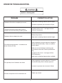
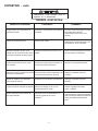
OPERATOR TROUBLESHOOTING
PROBLEM CORRECTIVE ACTION
Fasteners will not drive completely into wood.
Fasteners penetrate properly during normal
operation, but won't drive fully at faster speeds.
Fasteners drive too deeply into wood.
Tools skips during operation - no fasteners are
driven from time to time.
Tool operates, but no fasteners are driven.
Air leaks at cap when tool is connected to air.
Adjust work contacting element (retract length).
Increase air pressure (do not exceed 120 psi).
Increase air flow to tool -- use larger air lines
(3/8 inch ID minimum).
Adjust work contacting element (extend length).
Reduce air pressure.
Check magazine for proper fasteners. Magazine
follower should slide freely. Clean as needed to
remove debris.
Make sure correct fasteners are being used.
Use fasteners that meet Paslode specifications
only.
Increase air flow to tool -- use larger air lines
(3/8 ID minimum).
Adjust work contacting element where available.
Check magazine for proper fasteners. Fasteners
should slide freely with no follower pressure.
Increase air pressure (do not exceed 120psi).
Tighten cap screws.
CAUTION
Disconnect the tool when performing
repairs or clearing jams.
14

15
888 Forest Edge Drive
Vernon Hills, Illinois 60061
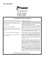
TOOL WARRANTY AND LIMITATIONS
TOOL WARRANTY
ONE-YEAR LIMITED WARRANTY
A one-year warranty will apply to all parts, except
those which are specifi
cally covered by an extended
warranty.
FIVE-YEAR EXTENDED LIMITED WARRANTY
A
ve-year warranty will apply to all housing and cap
assembly castings.
WARRANTY STATEMENT
This warranty is limited to tools sold and service requested
in the United States. To obtain information on warranty
service in the United States, refer to the Service Center
listing that was provided with your tool.
MODEL F325R
Framing Nailer
Paslode's sole liability hereunder will be to replace any
part or accessory which proves to be defective within the
speci
c time period. Any replacement part or accessory
provided in accordance with this warranty will carry a
warranty for the balance of the period of warranty appli-
cable to the part it replaces. This warranty does not apply
to part replacement required due to normal wear.
This warranty is void as to any tool which has been subjected
to misuse, abuse, accidental or intentional damage, use
with fasteners, not
specification, size,
or quality, improperly maintained, repaired with other than
genuine Paslode replacement parts, damaged in
transit or
handling, or which, in opinion, has been altered
or, repaired in a way that affects or detracts from the
®
MAKES NO WARRANTY, EXPRESSED OR
IMPLIED, RELATING TO MERCHANTABILITY, FIT-
NESS
,
OR
OTHERWISE,
EXCEPT
AS
STATED
ABOVE, AND
LIABILITY
AS
STATED ABOVE
AND
AS
ASSUMED ABOVE is in lieu of all other warranties arising
out of, or in connection with, the use and
performance of the
tool, except to the extent otherwise
provided by applic-
able law. PASLODE SHALL IN NO
EVENT BE LIABLE
FOR
ANY
DIRECT,
INDIRECT,OR CONSEQUENTIAL
DAMAGES,
INCLUDING,
BUT NOT
LIMITED TO, DAMAGES
WHICH MAY
ARISE FROM
LOSS OF ANTICIPATED
PROFITS OR PRODUCTION,
SPOILAGE
OF
MATERIALS,
INCREASED COST OF
OPERATION,
OR OTHERWISE.
An Illinois Tool Works Company
Paslode®
warrants that newly purchased power
fastening tools, parts and accessories will be free
from defects in material and workmanship for the
period shown below, after the date of delivery to
the original user.
®
®
Paslode reserves
the
right to
change
specifications,
equipment, or
designs
at any time without notice and without incurring obligation.
®
performance of the tool.
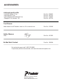
PASLODE

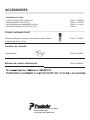
L
ubricants and Loctite
Loctite 242 (Blue) .20 oz. Part No. 093500
Lubricating Oil 16 oz. Part No. 403720
Lubricating Oil with Antifreeze 8 oz. Part No. 219090
Chemplex 710 Lubricant 1lb. Part No. 403734
Tool Cleaner
843912 .oN traPPaslode tools in a 12 oz. aerosol can. lla rof renaelc laedI
Safety Glasses
Clear Part No. 401382
ACCESSORIES
888 Forest Edge Drive
Vernon Hills, Illinois 60061-3105
No Mar Work Contact Part No. 502234
For technical support call 1-800-222-6990.
To purchase parts and accessories, visit www.itwconstructionparts.com.
An Illinois Tool Works Company
®

1
MODE D’EMPLOI ET
SCHÉMAS
IMPRIMÉ AUX ÉTATS -UNIS
© 2014, Illinois Tool Works Inc.
513057 -1
06/14
MODLE F325R
Cloueuse à Charpente
IMPORTANT!
NE DÉTRUISEZ PAS
Il incombe au client de s’assurer que tous les
utilisateurs et le personnel d’entretien et de
réparation lisent et comprennent ce guide.

La cloueuse à charpente pour rénovation modèle F325R de Paslode
®
est un outil de qualité
conçu pour être utilisé pour les travaux de charpentes résidentielles.
................................................... 3
.
.................................................................................. 4
.
.......................................................5-6
.
............................................................................................... 7-8
.
.................................................................. 9
.
..................................... 10-11
.
................................................................................................... 12-13
.
..................................................................................................... 14
.
.......................................................................................................... 15
.
.................................................................................................. 16
2
INTRODUCTION
Cet outil fournira un rendement efficace et fiable s’il est utilisé conformément aux instruc-
tions du fabricant. Veuillez étudier ce mode d’emploi y compris les consignes de sécurité
pour bien comprendre le fonctionnement de cet outil.
CARACTÉRISTIQUES DE L’OUTIL ET ATTACHES
CONSIGNES DE SÉCURITÉ
INSTALLATION ET UTILISATION DE L’OUTIL
SYSTÉME D’AIR
CARACTÉRISTQUES ET AVANTAGES
VUE ÉCLATÉE ET LISTE DES PICES DE RECHANGE
ENTRETIEN
DÉPANNAGE
GARANTIE
ACCESSORIES

CARACTÉRISTIQUES DE L’OUTIL ET ATTACHES
CARACTÉRISTIQUES DE L’OUTIL
MODÈLE N°
F325R (Pièce n° 513000)
HAUTEUR
32,7 cm (12,9 po)
LARGEUR
10,9 cm (4,3 po)
LONGUEUR
31,2 cm (12,3 po)
POIDS
2,6 kg (5,9 lb)
PRESSION DE FONCTIONNEMENT
6,2 à 8,3 bars (90 à 120 p.s.i.)
TYPE DE MAGASIN
30 degrés, à une seule bande
CARACTÉRISTIQUES DES ATTACHES
L
ONGUEUR DES CLOUS
5 cm à 8,2 cm (2 po à 3¼ po)
DIAMÈTRE DE LA TIGE
2,8 mm à 3,3 mm (0,113 à 0,131 po)
R
ACCORDS À AIR DE L’OUTIL :
Cet outil utilise un raccord mâle de 3/8
po N.P.T. Le raccord
d
oit pouvoir libérer la
pression d’air de l’outil lorsqu’il est débranché de l’alimentation en air.
PRESSION D'AIR DE FONCTIONNEMENT :
6,2 à 8,3 bars (90 à 120 p.s.i.). Choisissez une pression d’air de fonctionnement
comprise dans cette plage pour obtenir le meilleur rendement de l’outil.
NE DÉPASSEZ PAS CETTE PRESSION DE FONCTIONNEMENT RECOMMANDÉE.
3

INSTRUCTIONS SUR LA S
É
CURIT
É
LA SÉCURITÉ AVANT TOUT
Ces instructions se rapportant à la sécurité donnent l'information
nécessaire pour manipuler les outils Paslode en toute sécurité.
NE PAS ESSAYER D'OPÉRER L'OUTIL AVANT D'A
VOIR LU ET
COMPRIS T
OUTES LES PRÉCAUTIONS À PRENDRE ET LES
INSTRUCTIONS DU MANUEL.
PORTER DE L'ÉQUIPEMENT DE PROTECTION
POUR LES YEUX ET L'OUÏE.
Toujours porter de l'équipement de protection pour
les yeux et l'ouïe qui se conforment aux normes
ANSI
Z87.1 lors de l'opération de l'outil ou à proximité. En
tant qu'employeur
, il en est de votre responsabilité de
vous assurer du port de l'équipement de protection.
Porter des casques de sécurité lorsque nécessaire.
L'OUTIL NE DOIT ÊTRE UTILISÉ QUE POUR SON USAGE
PRÉVU.
Ne pas jeter l'outil à terre, frapper le boîtier de quelque façon que
ce soit ou utiliser l'outil comme marteau pour enfoncer la pièce
en place.
NE JAMAIS INITIER DES JEUX BRUTAUX AVEC L'OUTIL
Cet outil n'est pas un jouet donc ne pas l'utiliser comme tel. Ne
jamais initier des jeux brutaux avec l'outil ou le pointer vers vous
ou toute autre personne, même si vous croyez que l'outil n'est
pas chargé.
NE JAMAIS PRÉSUMER QUE L'OUTIL EST VIDE
Vérifiez le magasin pour des attaches qui pourraienty reste
r
.
Même si vous croyez que l'outil est vide ou est désaccouplé, ne
jamais le pointer vers vous ou vers une autre personne. L'outil
pourrait décharger des attaches non remarquées.
NE JAMAIS PINCER LA GÂCHETTE EN POSITION BARRÉE
OU OPÉRATIONNELLE.
Ne jamais modifie
r
, mettre hors service ou pincer la gâchette de
l'outil en position barrée ou opérationnelle, puisque ceci permet-
trait à l'outil d'enfoncer une attache, n'importe quand, lorsque
l'élément de pointe de contact touche la pièce de travail.
NE P
AS CHARGER LES
A
T
T
ACHES LORSQUE LA SOURCE
D'AIR EST ACCOUPLÉE, LA GÂCHETTE EST PRESSÉE OU
L'ÉLÉMENT DE POINTE DE CON
T
ACT TOUCHE LA PIÈCE
DE TRAVAIL.
Assurez-vous d'avoir désaccouplé l'entrée d'air et que la gâchette
et la pointe de contact ne sont pas pressées lorsque vous
rechargez l'outil.
N'OPÉREZ L'OUTI
L
QUE SUR UNE SUR
F
ACE DE
TRAVAIL
L'outil ne devrait être opéré que lorsqu'il est en contact
avec la pièce de travail. Même dans cette situation,
doublez de précaution avec les pièces de travail
minces, ou près des bords et dans les coins, puisque
les attaches pourraient traverser ou faire ricochet de la pièce de
travail.
NE PAS ENLEVER OU METTRE HORS SE
R
VICE L'ÉLÉMENT
DE POINTE DE CONTACT
L'outil est équipé d'un mécanisme de sécurité, l'élément de pointe
de contact, afin de prévenir la décharge accidentelle. Ne jamais
modifier
, enlever ou mettre hors service l'élément de pointe de
contact. Ne pas utiliser l'outil à moins que l'élément de pointe de
contact ne fonctionne proprement. L'outil pourrait se décharger
accidentellement.
DÉSACCOUPLER L'OUTIL LORSQUE REMISÉ
T
oujours désaccoupler l'outil de la source d'air lorsqu'il est remisé,
lorsque vous quittez le chantier de travail ou que vous transportez
l'outil vers un autre endroit. L'outil ne doit jamais être laissé sans
surveillance, puisque de tierces personnes, non familières avec
son fonctionnement pourraient le manipuler et causer des bles-
sures.
NE TRANSPORTER L'OUTIL QUE PAR SA
POIGNÉE
T
oujours transporter l'outil uniquement pas sa
poignée. Ne jamais transporter l'outil par le tuyau
d'air ou avec la gâchette pressée puisque vous
pourriez décharger l'outil accidentellement et vous
blesser ou blesser une autre personne.
NE PAS AFFAIBLIR LE BOITIER DE L'OUTIL
Le boitier de l'outil est un conduit de pression et ne devrait jamais
être af
faibli en faisant graver ou poinçonner le nom de votre
entreprise, lieu de travail ou toute autre information sur sa surface.
DÉSACCOUPLER L'OUTI
L
LORS DE L'ENTRETIEN OU DES
DÉBLOCAGES
Ne jamais tenter de débloquer ou de réparer l'outil avant de
désaccoupler l'outil de la source d'air et d'enlever toutes attaches
de l'outil.
T
OUJOURS UTILISER LE BON RACCORD POUR L'OUTIL
N'utiliser que les raccords MÂLES de type pneumatique pour
l'outil, afin que la haute pression d'air dans l'outil puisse se dissiper
dans l'atmosphère dès que la ligne à air est désaccouplée.
Ne JAMAIS installer des raccords FEMELLES à désaccouplement
rapide sur l'outil. Les raccords femelles retiennent la haute
pression d'air dans l'outil lorsque la source d'air est désaccouplée,
laissant ainsi l'outil chargé et capable d'enfoncer une attache.
NE JAMAIS DÉ
PASSER LA
PRESSION D'AIR
MAXIMUM RECOMMANDÉE
N'opérer l'outil que dans les limites de pressions
recommandées. Ne pas dépasser la pression d'air
indiquée sur l'outil.
Assurez-vous que la jauge de
pression fonctionne adéquatement et en vérifier le
bon fonctionnement au moins deux fois par jour.
Ne jamais utiliser de l'air comprimé ou autre gaz en
bouteille tel que de l'oxygène pour faire fonctionner
l'outil, ceci pourrait faire exploser l'outil.
INSPECTER L'OUTIL
POUR SON BON FONCTIONNEMENT
Nettoyer l'outil tous les jours et le lubrifier au besoin. Ne jamais
opérer un outil sale ou qui ne fonctionne pas bien.
N'UTILISER QUE LES PIÈCES ET ATTACHES PASLODE
RECOMMANDÉES
N'utiliser que les pièces et les attaches spécifiquement conçues
et recommandées par Paslode pour l'outil et pour le travail à
accomplir. L'utilisation de pièces et attaches non autorisées ou
toute modification de l'outil créent des situations dangereuses.
Remplacez toutes les étiquettes d'avis – reportez vous au schéma
de l'outil pour l'emplacement et le numéro de pièce.
4
Le manque à suivre n'importe laquelle des instructions ci-haut mentionnées pourrait résulter en des
blessures sérieuses à l'utilisateur et tierces personnes et pourrait endommager l'outil et autres biens.
Communiquez avec votre représentant Paslode pour une présentation du Programme de Sensibilisation sur la Sécurité de Paslode.
AVIS
La page est en cours de chargement...
La page est en cours de chargement...
La page est en cours de chargement...
La page est en cours de chargement...
La page est en cours de chargement...
La page est en cours de chargement...
La page est en cours de chargement...
La page est en cours de chargement...
La page est en cours de chargement...
La page est en cours de chargement...
La page est en cours de chargement...
La page est en cours de chargement...
-
 1
1
-
 2
2
-
 3
3
-
 4
4
-
 5
5
-
 6
6
-
 7
7
-
 8
8
-
 9
9
-
 10
10
-
 11
11
-
 12
12
-
 13
13
-
 14
14
-
 15
15
-
 16
16
-
 17
17
-
 18
18
-
 19
19
-
 20
20
-
 21
21
-
 22
22
-
 23
23
-
 24
24
-
 25
25
-
 26
26
-
 27
27
-
 28
28
-
 29
29
-
 30
30
-
 31
31
-
 32
32


Paslode F325R Compact Framing Nailer Le manuel du propriétaire
- Catégorie
- Outils électroportatifs
- Taper
- Le manuel du propriétaire
dans d''autres langues
Documents connexes
-
Paslode 650385C Manuel utilisateur
-
-
-
-
-
-
Paslode CFN325XP Manuel utilisateur
-
Paslode 905600 Manuel utilisateur
-
-