KitchenAid KSSO36QMB02 Guide d'installation
- Catégorie
- Frigos
- Taper
- Guide d'installation
Ce manuel convient également à

®itchen_kid ®
SIDE BY SIDE BUILT-IN REFRIGERATOR
IMPORTANT: READ AND SAVE THESE INSTRUCTIONS. INSTALLATION REQUIRES 2 OR MORE PEOPLE.
REFRIGERADOR EMPOTI_DOS
DE DOS PUERTAS
IMPORTANTE: LEA Y GUARDE ESTAS INSTRUCCIONES. LA INSTALACION REQUIERE DE 20 MAS PERSONAS.
REFRIGERATEUR ENCASTRES COTE A COTE
IMPORTANT :LIREET CONSERVERCES INSTRUCTIONS.L'INSTALLATIONN¢:CESSITEL'INTERVENTIONDE2 PERSONNESOU PLUS.
Table of Contents/Jndice/Table des matieres .................................................................. 2
2266811A

TABLEOF
REFRIGERATOR SAFETY ............................................................. 3
DESIGN SPECIFICATIONS ............................................................ 4
Models .......................................................................................... 4
Product Dimensions ..................................................................... 6
Tipping Radius ............................................................................. 7
Door Swing Dimensions ............................................................... 7
Handle and Door Clearances ....................................................... 8
Classic Series Factory Panels and Kits ..................................... 11
Classic Series Custom Panels ................................................... 11
Overlay Series Custom Panels .................................................. 13
Classic, Architect ®and Pro LineTM Series Custom Side Panels. 14
Overlay Series Custom Side Panels .......................................... 14
INSTALLATION REQUIREMENTS .............................................. 15
Tools and Parts .......................................................................... 15
Location Requirements .............................................................. 16
Electrical Requirements ............................................................. 17
Water Supply Requirements ...................................................... 17
CONTENTS
INSTALLATION INSTRUCTIONS ................................................ 18
Unpack Refrigerator ................................................................... 18
Reduce Tipping Radius .............................................................. 18
Install Anti-Tip Boards ................................................................ 19
Connect Water Supply ............................................................... t 9
Plug in Refrigerator ..................................................................... 20
Move Refrigerator to Final Position ............................................ 20
Lower Leveling Legs .................................................................. 20
Install Classic Series Custom Panels ......................................... 20
Install Overlay Series Custom Panels ........................................ 21
Level Refrigerator ....................................................................... 22
Adjust and Remove Doors ......................................................... 23
Install Side Panel ........................................................................ 24
Install Base Grille ........................................................................ 24
Complete Installation .................................................................. 24
P
INDICE
SEGURIDAD DEL REFRIGERADOR ........................................... 25
ESPECIFICACIONES DE DISEI_IO .............................................. 26
Modelos ...................................................................................... 26
Medidas del producto ................................................................ 28
Arco de vuelco ........................................................................... 29
Medidas de oscilaci6n de las puertas ....................................... 29
Espacios para la agarradera y la puerta .................................... 30
Paneles y juegos de fabrica de la Serie Classic ........................ 33
Paneles de la puerta a la medida para la Serie Classic ............ 33
Paneles a la medida de la Serie Overlay ................................... 35
Paneles laterales a la medida para las
Serie Classic, Architect _y Pro LineTM ......................................... 36
Paneles laterales a la medida para la Serie Overlay .................. 36
REQUISITOS DE INSTALACION ................................................. 37
Piezas y Herramientas ............................................................... 37
Requisites de ubicaci6n ............................................................. 38
Requisites electricos .................................................................. 39
Requisitos del suministro de agua ............................................. 39
INSTRUCCIONES DE INSTALACION ......................................... 40
C6mo desempacar su refrigerador ............................................ 40
C6mo reducir el arco de vuelco ................................................. 40
C6mo instalar los tableros antivuelco ........................................ 41
C6mo conectar el suministro de agua ....................................... 41
C6mo enchufar el refrigerador ................................................... 42
Ubicaci6n final del refrigerador .................................................. 42
Baje las patas niveladoras ......................................................... 43
C6mo instalar los paneles a la medida para la Serie Classic....43
C6mo instalar los paneles a la medida para la Serie Overlay ...44
C6mo nivelar el refrigerador ....................................................... 45
Ajuste y quite las puertas ........................................................... 45
C6mo instalar el panel lateral ..................................................... 46
C6mo instalar la rejilla de la base .............................................. 47
C6mo terminar la instalaci6n ..................................................... 47
TABLE DES MATIERES
SI_CURITE DU REFRIGERATEUR .............................................. 48
SPECIFICATIONS DE DESIGN .................................................... 49
Modeles ...................................................................................... 49
Dimensions du produit ............................................................... 51
Rayon de basculement .............................................................. 52
Dimensions pour le pivotement des portes ............................... 52
D_gagements pour les poignees et portes ............................... 53
Ensembles de panneaux d'origine de la serie Classic .............. 56
Panneaux personnalises de la Serie Classic ............................. 56
Panneaux personnalises de la serie Overlay ............................. 58
Panneaux lateraux personnalises des
Series Classic, Architect®et Pro LineTM. ...................................... 59
Panneaux lateraux personnalises de la Serie Overlay .............. 59
EXIGENCES D'INSTALLATION ................................................... 60
Outillage et pieces necessaires ................................................. 60
Exigences d'emplacement ......................................................... 61
Specifications electriques ......................................................... 62
Specifications de I'alimentation en eau ..................................... 62
INSTRUCTIONS D'INSTALLATION ............................................. 63
Deballage du refrigerateur .......................................................... 63
Reduction du rayon de basculement ......................................... 63
Installation de planches antibasculement .................................. 64
Raccordement de la canalisation d'eau .................................... 65
Brancher le refrigerateur ............................................................. 65
Deplacement du refrigerateur a I'emplacement final ................. 65
Deploiement des pieds de nivellement ...................................... 66
Installation des panneaux personnalises de la Serie Classic....66
Installation des panneaux personnalises de la Serie Overlay ...67
Nivellement du refrigerateur ....................................................... 69
Ajustement et enlevement des portes ....................................... 69
Installation du panneau lateral ................................................... 70
Installation de la grille de la base ............................................... 71
Achever I'installation .................................................................. 71

REFRIGERATOR SAFETY
Your safety and the safety of others are very important.
We have provided many important safety messages in this manual and on your appliance. Always read and obey all safety
messages.
This is the safety alert symbol.
This symbol alerts you to potential hazards that can kill or hurt you and others.
All safety messages will follow the safety alert symbol and either the word "DANGER" or "WARNING."
These words mean:
You can be killed or seriously injured if you don't immediately/
follow instructions.
You can be killed or seriously injured if you don't follow
instructions.
All safety messages will tell you what the potential hazard is, tell you how to reduce the chance of injury, and tell you what can
happen if the instructions are not followed.
Tip Over Hazard
Refrigerator is top heavy and tips easily when not
completely installed.
Keep doors taped closed until refrigerator is
completely installed.
Use two or more people to move and install
refrigerator.
Failure do so can result in death or serious injury.

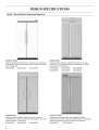
DESIGN SPECIFICATIONS
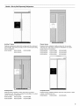
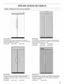
Models - Side by Side Non-Dispensing Refrigerators
Architect ®Series
Features wraparound styling that complements the contoured
door handles. This series provides a warm commercial-looking
built-in refrigerator.
KSSC36FMS KSSC42FMS KSSC48FMS
Classic Series
Features factory-installed, traditional style trim to provide a
"framed" look. This series requires the installation of custom
panels that are not included.
KSSS36FMB KSSS42FMB KSSS48FMB
KSSS36FMX KSSS42FMX KSSS48FMX
Overlay Series
Features factory-installed, overlay style trim to provide a
"frameless" look. This series requires the installation of custom
panels, handles, and standoffs.
KSSO36FMX KSSO42FMX KSSO48FMX
Pro Line TM Series
Features extraordinary design and exceptional levels of
performance. This series is a perfect blend of form and function
delivering professional quality, durability and simplicity.
KSSV42FMS KSSV42FMM

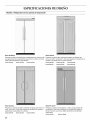
Models - Side by Side Dispensing Refrigerators
Architect ®Series
Features wraparound styling that complements the contoured
door handles. This series provides a warm commercial-looking
built-in refrigerator.
KSSC36QMS KSSC42QMS KSSC48QMS
KSSC42QMU
/'i n!!!um|!!!!!!!!|!!!m,|!!!mi i
Classic Series
Features factory-installed, traditional style trim to provide a
"framed" look. This series requires the installation of custom
panels that are not included.
KSSS36QMB KSSS42QMB KSSS48QMB
KSSS36QMW KSSS42QMW KSSS48QMW
KSSS36QMX KSSS42QMX KSSS48QMX
iiil
Overlay Series
Features factory-installed, overlay style trim to provide a
"frameless" look. This series requires the installation of custom
panels, handles, and standoffs.
KSSO36QMB KSSO42QMB KSSO48QMB
KSSO36QMW KSSO42QMW KSSO48QMW
Complete Series
Features factory-installed stainless steel trim and panels to create
a sleek, contemporary look.
KSSP36QMS KSSP42QMS KSSP48QMS

_!i __ _ _ _ __o_:_
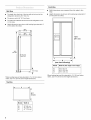
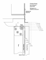
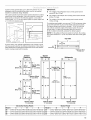
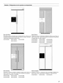
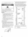
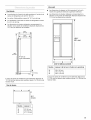
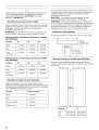
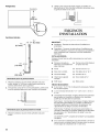
Side View
• The depth from the front of the top grille to the back of the
refrigerator cabinet is 25%" (64 cm).
• The power cord is 84" (213 cm) long.
• The water line attached to the back of the refrigerator is 5 ft.
(1.5 m)long.
• Height dimensions are shown with leveling legs extended %"
(3 mm) below the rollers.
.831/8"
(211 cm)
Y :
251/8''
(64 cm)
231/2"
(60 ore)
1
84" (213 cm)
Power Cord
_t "31/2" (9 cm)
*When leveling legs are fully extended to 1W' (32 mm) below
rollers, add 1V8"(29 mm) to the height dimensions.
Top View
Front View
• Width dimensions were measured from trim edge to trim
edge.
• Height dimensions are shown with leveling legs extended W'
(3 mm) below the rollers.
"83V_"
(211 cm)
v
(see chart following)
_f
Model Width A (Trim edge to trim edge)
36 36%" (92 cm)
42 42W' (107 cm)
48 48%" (123 cm)
*When leveling legs are fully extended to 1W' (32 mm) below
rollers, add 1%" (29 mm) to the height dimensions.
A
25V_"
(64 cm)
Model Width A
36 35" (89 cm)
42 41" (104 cm)
48 47" (119 cm)

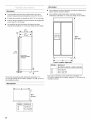
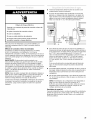
Besurethereisadequateceilingheighttostandtherefrigerator
uprightwhenitismovedintoplace.
• Thedollywheelheightmustbeaddedtothetippingradius
whenadollyisused.
• Ifneeded,thetippingradiuscanbereduced.See"Reduce
TippingRadius."
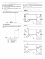
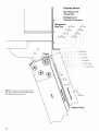
Forward Tipping Radius
The forward tipping radius is the same for all models.
871/4''
(222 cm) _L 7
Side Tipping Radius
The side tipping radius varies depending upon the width of the
model. Use the chart provided to determine the side tipping
radius.
//
/
/
/
/
/
/
/
/
f
/
/
A
r_r_ j
Model Tipping Radius A
36 901/2"(229.9 cm)
42 93" (236.2 cm)
48 96" (243.8 cm)
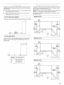
The location must permit both doors to open to a minimum of
90°. Allow 41/2'' (11.4 cm) minimum space between the side of the
refrigerator and a corner wall.
NOTE: More clearance may be required if you are using overlay
panels or custom handles.
To adjust the door swing, see the "Adjust Doors" section.
36 Models
141/2``
(37 crn)
#
40"
(102 cm)
_-- 193/4"--_
(50cm)
431/2-
!10cm)
m
I
42 Models
17%"
(_4cm)
197cJm)
48 Models
19_/4''
(50cm)
(102_Jm "
43112,,
45%"
(115cm)
"_-26_/""--_ 501/_''
(68cm)
(128cm)
\
\\, 9o"

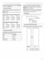
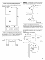
If you are installing custom panels, the panels must allow certain clearances for the handles and for the doors to swing open. First,
determine the types of handles you will be using and the door stop setting. Then, choose the appropriate scale drawing to use as a
template for creating the panels.
Classic
Handle
Optional
Extended
Handle
Door
Custom Panel
Architect ® Handle
Handle Dimensions
Actual Size
......... V4"(6.35 mm)
_/_"(1.3 cm)
3/4"(1.9 cm)
1" (2.5 cm)
1_/4"(3.2 cm)
1_/_"(3.8 cm)
13/4"(4.4 cm)
2" (5.1 cm)
2V4"(5.7 cm)
2V_"(6.4 cm)
23/4"(7 cm)
3" (7.6 cm)
" 2" 3"
(2.5 cm) (5.1 cm) (7.6 cm)

I
[
0
0 Hinge
Spacer Panel
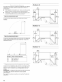
Overlay Series
Door Swing 90 °
Actual Size
Refrigerator to
Cabinetry Clearance
Refrigerator
Side Trim
i
i I i
i I i
, , ---7 .... t-___4.
i I i I I
i I I I
i I I I
--÷------4 .... J- I. 1
I I I I
I I I I
I I I I
i i i
i
--T .... i .... T-- 7 --_ .... +
1/2'
(1.3cm)i
3/4"
(1.9 cm)
1"
(2.5cm)
0
<
E
1/4"(6.35 mm)
1/2"(1.3 cm)
3/4"(1.9 cm)
1" (2.5 cm)
11/4"(3.2 cm)
11/2"(3.8 cm)
1 1/4"
(3.2 cm)
11/£'
(3.8cm)

O
O
O
Hinge
®
NOTE: Do not place the door stop screw in
the 130° position on Overlay Series models.
See "Adjust and Remove Door."
Overlay Series
Door Swing 110 °
Actual Size
Refrigerator to
Cabinetry Clearance
Refrigerator 1" 2"
Side Trim (2.5 cm) (5.1 cm)
3/4" 13/4" ',
(1.9 cm) (4.4 cm)i
1/2" 11/2" i
(1.3 cm) (3.8 cm)',
1/4" 11/4" ',
(6.35 mm) (3.2 cm)',
r
j
j
1/2"(1.3 cm)
3/4"(1.9 cm)
1" (2.5 cm)
11/4"(3.2 cm)
1lh" (3.8 cm)
Spacer Panel
10

_iii'iiiiii_i!i_!!!i;;!_!;!ii_:::i!'!i;_i?_i_i:ii_i?_i_iiii!:_;ii!_:di:o_:iii!!i,_¸'i!_ii!_i:_;i:iiii!_i,:_;_il;i_i:_i_,_;:i!iiiii::i:;iiii_i_:_!_!;,
All factory parts are available through your KitchenAid dealer or
by calling KitchenAid Parts and Accessories at 1-800-442-9991.
In Canada, call 1-800-807-6777.
Four kits containing colored acrylic or stainless steel door and
top grille panels are available. Follow the kit instructions for
installing the panels.
NOTE: Panel kits are not required for factory-installed stainless
steel panel models.
Door Panel Part Numbers for Non-dispenser Models
Color 36 42 48
White #2220852 #2220853 #2220854
Black #2220855 #2220856 #2220857
Stainless #2220861 #2220862 #2220863
Steel
Door Panel Part Numbers for Dispenser Models
Color 36 42 48
White #2220864 #2220865 #2220866
Black #2220867 #2220868 #2220869
Stainless #2220873 #2220874 #2220875
Steel
Extended Door Handle Kits
Use extended door handles when additional finger clearance is
needed between the door handles and custom panel. Follow the
kit instructions for installing the door handles.
Color Part Number
White #4387990
Black #8171418
Stainless Steel #4388062
Matte Aluminum #4387989
If you plan to install custom wood panels, you will need to create
the panels yourself or consult a qualified cabinetmaker or
carpenter. See dimensional drawings for panel specifications.
IMPORTANT: Panels weighing more than recommended may
cause damage to your refrigerator.
NOTE: Dimensions shown have a (+_ 1/1_"(1.5 mm) tolerance.
Panels that are more than 1/4"(6.35 mm) thick must be routed. If
panels are less than 1/4"(6.35 mm) thick, install a filler panel
between the doors and decorative panels.
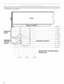
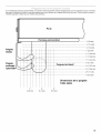
Top Grille Panel
The top panel should not weigh more than 10 Ibs. (4.5 kg).
_(18.4 cm)
Model A
36 35%" (90 cm)
42 41%" (105 cm)
48 47%" (120 cm)
Door Panels for Non-dispenser Models
The freezer panel should not weigh more than 30 Ibs. (13.5 kg).
The refrigerator panel should not weigh more than 50 Ibs. (23 kg).
•,_e--- A---4_ ,,_-_ B-_-
Model A B
36 141/4'' (36 cm) 191/4'' (49 cm)
42 16_/4'' (43 cm) 22_/4'' (58 cm)
48 191/4'' (49 cm) 261/4'' (67 cm)
11

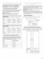
Door Panels for Dispenser Models
The two freezer panels combined should not weigh more than
30 Ibs. (13.5 kg). The refrigerator panel should not weigh more
than 50 Ibs. (23 kg).
237/1_''
[60crn)
7
347/1_''
[87cm)
m
Model A B
36 141/4'' (36 cm) 191/4'' (49 cm)
42 163/4'' (43 cm) 223/4'' (58 cm)
48 191/4'' (49 cm) 261/4'' (67 cm)
(179cm)
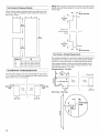
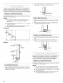
Top Grille Panel - Routing Requirements
Top and bottom edges of the top panel should be edge routed
1/2"(1.3 cm) and %" (9.5 mm), respectively. Both ends should be
1/4"
(6.35 ram) _-[--
max.
(2.2 era)
edge routed 7/8"(2.2 cm) as shown.
Top /
Top
Grills
1, :'35
max.
(2.2 cm)
NOTE: When creating a panel with face detail, the offsets will be
hidden and must be accounted for in order to center the detail in
the top grille.
_1/4"
(6.35 mm) max
1/2" I Top
(1.3 cm)
min.
detail between
offsets
3,°,,
(9.5 mm) L
min. Bottom
--(6.35 mm) max
Door Panels - Routing Requirements
If an extended handle kit is used, then routing the handle side of
the panels is not required. See "Classic Series Factory Panels
and Kits" for more information on ordering extended handles.
If the standard handle is used, route the entire handle side of
both panels 31/4'' (8.25 cm) to allow for finger clearance. Then
route the other sides 1" (2.54 cm).
Standard Handle - Top View
@
_d
=r
31/4 _'
_-_ (8.25 cm) _1
min. _ I Hinge Side
r= __1
o
_/4"(6.35ram) m Panel Panel
2" (5 cm) 1"
min. (2.54 cm)
Door Panel - Side View
V="(1.3 cm)
r-
13_
12

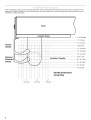
Custom overlay panels allow you to blend the exterior of your
refrigerator into the overall kitchen decor, and to use custom
handles for additional design flexibility.
The custom panels must have backer panels attached in order to
mount them to the refrigerator. It is most common to work with
three panels, as shown in the following graphic: a decorative
overlay panel, a 1/8" (3.18 mm) spacer panel or spacer strips and
a 1/4"(6.35 mm) backer panel.
[ Overlay Pahel Spacer Paliel 1
_'\ _i Backer Panel
%" to 3/4" ii_r_
%" (B,35mm)
(3.18mrn)
Spacer Panel
In some cases, your cabinet manufacturer may choose to work
with one panel routed for the different dimensions. Follow these
panel dimension and placement instructions to be sure that the
custom overlay panels will fit properly.
IMPORTANT:
• The weight of the refrigerator door overlay panel cannot
exceed 50 Ibs. (23 kg).
The weight of the freezer door overlay panel cannot exceed
30 Ibs. (13.5 kg).
The weight of the top grille overlay panel cannot exceed
10 Ibs. (4.5 kg).
To minimize panel weight, you may use 2" (5.08 cm) spacer strips
around the perimeter in place of full-sheet solid spacer panels.
The spacer strips must be set in at least 1" (2.54 cm) from the
top, bottom and sides edges of the backer panel. If you use
spacer strips, it is also recommended that you use two 2"
(5.08 cm) strips horizontally centered for added support.
NOTE: For the grille and the door panels to be flush, the overlay
door panel should be 1/4"(6.35 mm) thicker than the overlay grille
panel.
Top Grille
I< C >
73/8-
(18.73 cm)
8V=,,T _J'
_* Bottom Offset
1" (2.54 cm)
Model
36
42
48
24"
(60.96 cm)
343/4',
(88.27 cm)
1
Freezer
Dispenser
,' I i
Handle-Side
; 237/le,, m
l (59.53 cm)mmOffset
__D=_ Vs" (3.2 mm)
| m
_ Bottom Offset
%" (3.2 mm)
_-_ A _
|||£4 ....D_"
Handle-Side
347/_e" Offset
(87.47 cm V_" (3.2 mm)
Bottom_ Offset
V_" (3.2 ram)
Freezer
Non-Dispenser
•,_---- A -----1_
|
|
|
|
|
|
|
|
|
|
|
70V_" |
',(179.07cm)',
|
|
|
|
|
|
_[-- - D_
Botto_mOffset
V_" (3.2 ram)
t
Handle-Side
Offset
Vs" (3.2 mm)
711/16"
(180.50 cm)
Refrigerator
70V2"
'179.07 cm)
_:- E-->
Botto_m Offset
V_" (3.2 mm)
Decorative Overlay Panels
A B C Model
14%" (37.15 cm) 19%" (49.85 cm) 34W' (87.63 cm) 36
171/8'' (43.50 cm) 231/8'' (58.74 cm) 40W' (102.87 cm) 42
19%" (49.85 cm) 26%" (67.63 cm) 46W' (118.11 cm) 48
Backer Panels
D E
147/18"(36.67 cm) 197A8'' (49.37 cm)
16|%6'' (43.50 cm) 22|%6'' (58.26 cm)
197/18'' (49.37 cm) 267/18'' (67.15 cm)
F
341/_'' (87.63 cm)
401/_'' (102.87cm)
461/_'' (118.11 cm)
13

iii,illiiiiii_!i_!!i!;_!ii,_:::::,_,_!!!_:_:_,_;::_i_i_i:_!iiiii_ii:_:ii_:::i_:!¸¸¸¸_¸_¸_ii,i_i_:::ii_!_/:_oiliLi_;_ii_,_:!!,"¸¸¸:i:!_:!!_i_ii_i_i!_!ii,i
_iiiiiiiu_!_ii_iii:o_!_!_!_:_:_iii!!iii_iii_i:_!!_i_!__iiii:_ii!_ii_i_!_iiii_!_!i!_i_
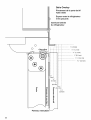
Custom side panels may be needed when not enough space is
available to have cabinets on both sides of the refrigerator or
when the refrigerator is placed at the end of a cabinet run. You
may choose an Inset, Flush, or Recessed Inset panel installation.
Refrigerator and Side Trim Dimensions
The width and height of a side panel is determined by the type of
installation you are planning.
NOTES:
• The dimensions shown are actual product dimensions
and may not reflect the needed panel installation
dimensions.
• The side panel should be a minimum of 1/2"(1.3 cm) thick
to prevent warping.
• If the opening depth is 25" (63.5 cm) or more, you may
want to install a support board on rear wall.
Refrigerator
241/8''
(61.3 cm)
(60.3 cm)
231/2''
(59.7 cm)
Side Trim
1/4H
(6.35 mm)
1/16 H ._
(1.5 mm)
7/32 II
(5.5 mm)
13/32"(10 mm)
5/3211
(4 mm)
Inset Installation Dimensions
1. Measure the distance from point A (as shown) to the back
wall. Add %2" (5.6 mm) to this measurement to allow the side
panel to fit into the trim.
2. If the panel is more than 1/4"(6.35 mm) thick, route the front
edge to allow the side panel to fit into the trim.
Flush Installation Dimensions
1. Measure the distance from point A (as shown) to the back
wall.
2. Attach the support board with a screw or adhesive that is
compatible with aluminum and wood.
A
Recessed Inset Installation Dimensions
1. Measure the distance from point A (as shown) to the back
wall.
2. Route the front edge of the support board or attach a 1/4"
(6.35 mm) board to hold the panel in the cabinet side trim.
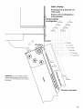
Custom side panels may be needed when not enough space is
available to have cabinets on both sides of the refrigerator or
when the refrigerator is placed at the end of a cabinet run. You
may choose an Inset or Recessed Inset panel installation.
Refrigerator and Side Trim Dimensions
The width and height of a side panel are determined by the type
of installation you are planning.
NOTES:
• The dimensions shown are actual product dimensions
and may not reflect the needed installation dimensions.
• The side panel should be a minimum of 1/2"(12 mm) thick
to prevent warping.
• If the opening depth is 25" (63.5 cm) or more, you may
want to install a support board on rear wall.
14

Refrigerator
Overlay
Recessed Inset Installation Dimensions
1. Measure the distance from point A (as shown) to back wall.
2. Route the front edge of the support board or attach a %"
(9.5 mm) board to hold the panel in the cabinet side trim.
Side Trim
3/16"
ram)
3 ii
/8 ._
(9.7 mm)
(1.5 mm)
!
118"-i-
(3.2 mm) 2
Inset Installation Dimensions
1. Measure the distance from point A (as shown) to the back
wall. Add 1/32"(0.8 mm) to this measurement to allow the side
panel to fit into the trim.
2. If the panel is more than %" (9.5 mm) thick, route the front
edge to allow the side panel to fit into the trim.
A
INSTALLATION
REQUIREMENTS
IMPORTANT:
• Installer: Leave Installation Instructions with the homeowner.
• Homeowner: Keep Installation Instructions for future
reference. Save these Installation Instructions for the local
electrical inspector's use.
TOOLS NEEDED:
Make sure that you have the tools necessary for proper
installation:
• Hand drill or electric drill • T27 flat-head 6 point
(properly grounded) driver
• Drill bits • 11/32"nut driver
• Two adjustable wrenches • %" and 1/_,,open-end
wrenches
• Phillips screwdriver • 3/=,,Allen wrench
• Small level • 3/16"socket wrench
• Appliance dolly • Tape measure
PARTS NEEDED:
• Six #8 x 3" (7.6 cm) wood screws (longer screws may be needed)
One or two 2" x 4" x 32" (5 cm x 10 cm x 81 cm) wood board(s)
Order factory panels, make custom panels or consult a
qualified cabinetmaker or carpenter to make the panels.
Classic Series: Order factory panels, make custom panels, or
consult a qualified cabinetmaker or carpenter to make the
panels. See "Design Specifications" for more information.
Overlay Series: Make custom panels, or consult a qualified
cabinetmaker or carpenter to make the panels. See
"Installation Requirements" and "Design Specifications" for
more information.
and Architect Series are shippedPro LineTM, Complete ®
complete.
If you are connecting the water line directly to copper tubing
and not to a shutoff valve, you need a ferrule, a union, and a
1/4"(6.35 mm) compression fitting.
15

The refrigerator can be recessed in an opening between cabinets
or installed at the end of a cabinet run using a side panel to
enclose the refrigerator.
E×plosion Hazard
Keep flammable materials and vapors, such as
gasomine, away from refrigerator.
Faimureto do so can resumt in death, e×pmosion, or fire.
IMPORTANT:
• Observe all governing codes and ordinances.
• Do not install the refrigerator near an oven, radiator, or
other heat source, nor in a location where the temperature
will fall below 55°F (13°C).
• Floor must support the refrigerator weight, more than
600 Ibs. (272 kg), door panels and contents of the
refrigerator.
• Ceiling height must allow for side or front tipping radius.
See "Tipping Radius."
• Location should permit doors to open fully. See "Door
Swing Dimensions."
• Location must permit top grille removal. See "Opening
Dimensions."
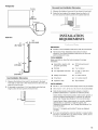
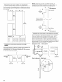
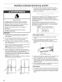
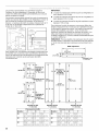
Opening Dimensions
The solid soffit must be within 1" (2.5 cm) maximum above
the refrigerator. If the solid soffit is higher than 1" (2.5 cm) or
one is not available, then the refrigerator must be braced to
prevent tipping during use.
If the anti-tip boards are needed, they must be attached to
the rear wall studs 80" to 90" (203 cm to 229 cm) above the
floor. See "Install Anti-Tip Boards" for more information.
NOTE: A clearance of 1/2"(1.3 cm) must be maintained above
the top grille in order for the top grille to be removed.
A grounded 3 prong electrical outlet should be placed within
4" (10.2 cm) of the right side cabinets or end panel. See
"Electrical Requirements" for additional information.
The water shutoff should be located in the base cabinet on
either side of the refrigerator or some other easily accessible
area. Ifthe water shutoff valve is not in the cabinets, the
plumbing for the water line can come through the floor or the
back wall. See "Water Supply Requirements" for more
information.
rain.
843/4'' (215 cm) max.
to bottom of solid soffit
A
Width
(see chart following)
3" (7.6 cm)
f 11,,
231/2'' (28 cm)
(60 cm) rain.
(10.2 cn
77"
(196 cm)
L
Model Width A (as shown above)
36 351/2"(90.2 cm)
42 411/2"(105.4 cm)
48 471/2'' (120.7 cm)
16

E(ectrical Shock Hazard
Pmuginto a grounded 3 prong outlet.
Do not remove ground prong,
Do not use an adapter,
Do not use an extension cord.
Failure to follow these }nstructions can reeumt }n death,
fire, or electrical shock.
Before you move your refrigerator into its final location, it is
important to make sure you have the proper electrical
connection.
Recommended Grounding Method
A 115 Volt, 60 Hz., AC only 15 or 20 amp fused, grounded
electrical supply is required, It is recommended that a separate
circuit serving only your refrigerator be provided. Use an outlet
that cannot be turned off by a switch, Do not use an
extension cord.
IMPORTANT: If this product is connected to a GFCI (Ground
Fault Circuit Interrupter) protected outlet, nuisance tripping of the
power supply may occur, resulting in loss of cooling. Food quality
and flavor may be affected, If nuisance tripping has occurred,
and if the condition of the food appears poor, dispose of it.
NOTE: Before performing any type of installation, cleaning, or
removing a light bulb, remove the top grille and turn the master
power switch to OFF or disconnect power at the circuit breaker
box.
When you are finished, turn ON the master power switch or
reconnect power at the circuit breaker box. Then reset the control
to the desired setting.
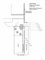
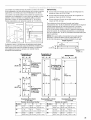
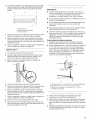
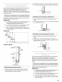
All installations must meet local plumbing code requirements.
The water shutoff should be located in the base cabinet on
either side of the refrigerator or some other easily accessible
area. The right-hand side is recommended. The access hole
through the right-hand side cabinet must be within 1/2"
(12.7 mm) of the rear wall.
3II (7.6 cm)
23112''
(60 crn) rain.
6It
(15.2 cm}
If the water shutoff valve is not in the cabinets, the plumbing
for the water line can come through the floor or the back wall.
A 1/2"(12.7 mm) hole for plumbing should be drilled 6"
(15.2 cm) to 12" (30.4 cm) from the right-hand side cabinet or
panel. On the floor, the hole should be no more than 11"
(28 cm) away from the back wall. On the wall, the hole should
be no more than 3" (7.6 cm) up from the floor. See "Connect
Water Supply."
If this recommended water line location is used, no additional
plumbing must be purchased.
• If additional tubing is needed, use copper tubing and check
for leaks. Install the copper tubing only in areas where the
household temperatures will remain above freezing.
• Do not use a piercing-type or 3/16"(4.76 mm) saddle valve
which reduces water flow and clogs more easily.
NOTE: Your refrigerator dealer has a kit available with a 1/4"
(6,35 ram) saddle-type shutoff valve, a union, and copper
tubing. Before purchasing, make sure a saddle-type valve
complies with your local plumbing codes.
Cold Water Supply
Connect the ice maker to a cold water line with water pressure
between 20 and 120 psi (138 - 827 kPa). If you have questions
about your water pressure, call your utility company.
17

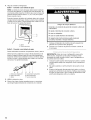
INSTALLATION INSTRUCTIONS
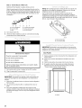
Tip Over Hazard
Refrigerator is top heavy and tips easily when not
completely installed.
Keep doors taped closed until refrigerator is
completely installed.
Use two or more people to move and install
refrigerator.
Failure do so can result in death or serious injury.
IMPORTANT:
• Do not remove the protective film or cardboard from door or
grille until the refrigerator is in its operating position.
• All 4 leveling legs must contact the floor to support and
stabilize the full weight of the refrigerator.
• Keep the cardboard shipping piece or plywood under the
refrigerator until it is installed in the operating position.
1. Remove the 4 brackets (2 on each side) that attach the
shipping base to the refrigerator bottom.
NOTE: Do not remove tape and door bracing until the
refrigerator is in its final position.
2. Place an appliance dolly under the freezer side of the
refrigerator. Be sure to protect the side trims and handles.
Place the corner posts from the packing materials over the
trims and handles as appropriate. Carefully tighten the strap.
NOTE: Pass the dolly strap under the handles for the
Architect ®Series.
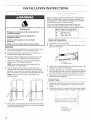
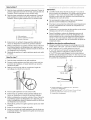
Before bringing the refrigerator into the home, be sure there is
adequate ceiling height to stand the refrigerator upright. See
"Tipping Radius" in the "Installation Requirements and Design
Specifications" section for more information.
If you do not have adequate ceiling height to stand the
refrigerator upright, the tipping radius can be reduced by
removing the top grille and side trims (see the following chart).
Model Reduced Tipping Radius
36 88" (223.5 cm)
42 881/2'' (224.8 cm)
48 891/4'' (226.7 cm)
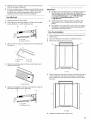
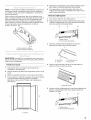
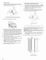
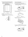
Classic and Overlay Series
1. Grasp both ends of the top grille.
2. Push the top grille straight up, then pull straight out. Lay the
grille on a soft surface.
B A B
A. Top grille
B. Cabinet side trim
3. Remove the 6 screws attaching each cabinet side trim to the
refrigerator and remove the side trims.
4. Stand the refrigerator up. First, place the left bottom edge of
the refrigerator on the floor, stand the refrigerator upright and
then lower the right-hand side of the refrigerator to the floor.
5. Reassemble the trim and top grille after the dolly has been
removed from the refrigerator.
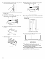
Architect _ Series
1. Grasp both ends of the louver panel. Push the louver panel
straight up, then pull straight out. Lay the panel on a soft
surface.
2. Grasp both ends of the top grille. Push the top grille straight
up, then pull straight out. Lay the top grille on a soft surface.
B A B
3=
Place pieces of the shipping carton on the floor when rolling
the dolly and refrigerator into the house. Move the refrigerator
close to the built-in opening.
A. Top grille
B. Cabinet side trim
C. Louver panel
18

3. Remove the 6 screws attaching each cabinet side trim to the
refrigerator and remove the side trims.
4. Stand the refrigerator up by first placing the left bottom edge
of the refrigerator on the floor, standing the refrigerator
upright and then lowering the right-hand side of the
refrigerator down to the floor.
5. Reassemble the trim and top grille after the dolly has been
removed from the refrigerator.
Pro Line TM Series
1. Grasp both ends of the top grille.
2. Push the top grille straight up, and then pull straight out.
3. Disconnect the wiring harness from the back of the top grille.
4. Lay the top grille on a soft surface.
5. Remove the 6 screws that attach each cabinet side trim to
the refrigerator, and remove the side trims.
6. Stand the refrigerator up. First, place the left bottom edge of
the refrigerator on the floor, stand the refrigerator upright and
then lower the right-hand side of the refrigerator to the floor.
7. After the dolly has been removed from the refrigerator,
reassemble the trim.
8. Reattach wiring harness into grille back.
9. Insert top grille hooks into slots on the side trim. Pull grille
down slightly to lock into place.
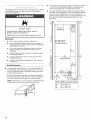
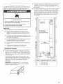
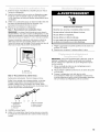
IMPORTANT:
• The solid soffit must be within 1" (2.5 cm) maximum above
the refrigerator. If the solid soffit is higher than 1" (2.5 cm) or
one is not available, prevent the refrigerator from tipping
during use as shown.
• It is recommended that board(s) be installed before the
refrigerator is installed.
• Board(s) must be long enough to fully cover the width of the
compressor cover.
• Locate the board(s) so the bottom surface(s) of the board(s)
is(are) 84" (213 cm) from the floor.
During installation, raise the refrigerator up so there is 1/4"
(6.35 mm) maximum between the top of the refrigerator and
the bottom of the anti-tip board(s). Do not crush the
condenser cover when raising the rear leveling legs.
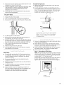
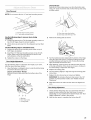
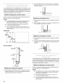
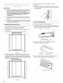
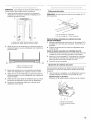
To Install Anti-tip Boards
1. Mark the stud locations on rear wall 80" to 90" (203 cm to
229 cm) above floor.
2. Securely attach one or two 2" x 4" x 32" (5 cm x 10 cm x
81 cm) wood boards to wall studs behind refrigerator. Use six
#8 x 3" (7.6 mm) (or longer) wood screws. The wood screws
must be screwed into the studs at least 11/2"(3.8 cm). The
board(s) must overlap the compressor cover.
A B
\
................... ii TM
2" (5 cm)
D
A. Center board _" (6.35 mm) max.above refrigerator
B. Two2" x 4" x 32" (5 cm x 10 cmx 81 cm)boards
C.Attach to studs with six #8 x 3" (7.6cm) screws
D. Compressor cover
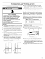
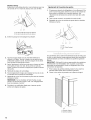
1. Remove the shipping tape from the gray, coiled water tubing
on the rear of the refrigerator.
2. Before attaching copper tubing to the refrigerator, flush at
least 2 qt. (1.9 L) of water through the copper tubing and into
a bucket to get rid of any particles in the water line.
3. Check for leaks around the saddle valve. Do not overtighten
the clamp or sleeve. This will crush the copper tubing.
4. Make connection to the refrigerator.
Style 1 - Connecting to a Water Valve:
NOTE: The water shutoff valve should be located in the base
cabinet on either side of the refrigerator. The right-hand side
is recommended. The access hole through the right cabinet
must be within 1/2"(12.7 mm) of rear wall.
Push the bulb end of the tubing into the water valve as far as
it will go. Slide the nut forward and finger tighten. Then
tighten it with a wrench two more turns. Do not overtighten.
A
B
A. Bulb
B. Nut (provided)
19

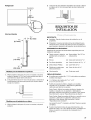
Style 2 - Connecting to a Water Line
Additional Parts Needed: Coupling, ferrule and nut.
Slide the purchased nut then the purchased ferrule onto the
tubing. Push the tubing into the purchased coupling as far as
it will go. Slide the nut and ferrule forward. Tighten the nut by
hand. Then tighten it with a wrench two more turns. Do not
overtighten.
5.
6.
A B b o
A.Line to refrigerator D. Coupling (purchased)
B. Nut (provided) E. Ferrule(purchased)
C. Bulb F Nut (purchased)
Turn shutoff valve ON.
Check for leaks. Tighten any nuts or connections (including
connections at the valve) that leak.
Emectrica_ Shock Hazard
Pmuginto a grounded 3 prong outlet.
Do not remove ground prong.
Do not use an adapter.
Do not use an extension cord.
Failure to follow these instructions can resumt in death,
fire, or eJectrical shock.
7. Set control switch at top of cabinet to the OFF position.
8. Plug into grounded 3 prong outlet.
IMPORTANT: To prevent floor damage, make sure levelers are
raised (not touching floor) and refrigerator is on rollers before
moving.
1. Place top of cardboard carton or plywood under refrigerator.
Remove dolly.
2. Do not remove protective film or cardboard from door or
grille.
3. Move the refrigerator straight back and evenly into the
opening. Check to make sure that water tubing is not kinked
and the power supply cord is on top of the refrigerator next to
the cover.
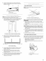
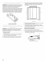
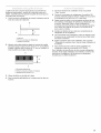
NOTE: All 4 leveling legs must contact the floor to support and
stabilize the full weight of refrigerator. Rollers are for moving
refrigerator and not for permanent support.
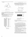
Use socket wrench to turn leg levelers on both sides of
refrigerator to the right (clockwise) until refrigerator weight is
supported by leveling legs. The rollers should be off the floor. To
avoid cabinet damage, do not apply more than 50 inch - pounds
(58 cm - kg) of torque to the leveling legs.
A B
A. Rear leveling legs
B, Front leveling legs
IMPORTANT: KitchenAid is not responsible for the removal or
addition of molding or decorative panels that would prevent the
refrigerator from being serviced.
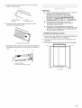
Door Panels
1. Remove all tape and door bracing from the refrigerator and
freezer doors.
2. Remove the screws that attach the handles to the door
frame.
3. Slide the decorative door panels into the door frames.
4. If needed, route the door panels or install a filler panel
between the doors and the decorative panels. See the
"Classic Series Custom Panels" section.
A .......
A. Panels
-A
20
La page est en cours de chargement...
La page est en cours de chargement...
La page est en cours de chargement...
La page est en cours de chargement...
La page est en cours de chargement...
La page est en cours de chargement...
La page est en cours de chargement...
La page est en cours de chargement...
La page est en cours de chargement...
La page est en cours de chargement...
La page est en cours de chargement...
La page est en cours de chargement...
La page est en cours de chargement...
La page est en cours de chargement...
La page est en cours de chargement...
La page est en cours de chargement...
La page est en cours de chargement...
La page est en cours de chargement...
La page est en cours de chargement...
La page est en cours de chargement...
La page est en cours de chargement...
La page est en cours de chargement...
La page est en cours de chargement...
La page est en cours de chargement...
La page est en cours de chargement...
La page est en cours de chargement...
La page est en cours de chargement...
La page est en cours de chargement...
La page est en cours de chargement...
La page est en cours de chargement...
La page est en cours de chargement...
La page est en cours de chargement...
La page est en cours de chargement...
La page est en cours de chargement...
La page est en cours de chargement...
La page est en cours de chargement...
La page est en cours de chargement...
La page est en cours de chargement...
La page est en cours de chargement...
La page est en cours de chargement...
La page est en cours de chargement...
La page est en cours de chargement...
La page est en cours de chargement...
La page est en cours de chargement...
La page est en cours de chargement...
La page est en cours de chargement...
La page est en cours de chargement...
La page est en cours de chargement...
La page est en cours de chargement...
La page est en cours de chargement...
La page est en cours de chargement...
La page est en cours de chargement...
-
 1
1
-
 2
2
-
 3
3
-
 4
4
-
 5
5
-
 6
6
-
 7
7
-
 8
8
-
 9
9
-
 10
10
-
 11
11
-
 12
12
-
 13
13
-
 14
14
-
 15
15
-
 16
16
-
 17
17
-
 18
18
-
 19
19
-
 20
20
-
 21
21
-
 22
22
-
 23
23
-
 24
24
-
 25
25
-
 26
26
-
 27
27
-
 28
28
-
 29
29
-
 30
30
-
 31
31
-
 32
32
-
 33
33
-
 34
34
-
 35
35
-
 36
36
-
 37
37
-
 38
38
-
 39
39
-
 40
40
-
 41
41
-
 42
42
-
 43
43
-
 44
44
-
 45
45
-
 46
46
-
 47
47
-
 48
48
-
 49
49
-
 50
50
-
 51
51
-
 52
52
-
 53
53
-
 54
54
-
 55
55
-
 56
56
-
 57
57
-
 58
58
-
 59
59
-
 60
60
-
 61
61
-
 62
62
-
 63
63
-
 64
64
-
 65
65
-
 66
66
-
 67
67
-
 68
68
-
 69
69
-
 70
70
-
 71
71
-
 72
72


KitchenAid KSSO36QMB02 Guide d'installation
- Catégorie
- Frigos
- Taper
- Guide d'installation
- Ce manuel convient également à
dans d''autres langues
Documents connexes
-
KitchenAid KBLC36FTS06 Guide d'installation
-
-
-
-
-
-
KitchenAid KSSO36FTX18 Guide d'installation
-
-
-
Autres documents
-
Jenn-Air JUR248LBCX00 Le manuel du propriétaire
-
Jenn-Air JS42CXFXDB Guide d'installation
-
-
Jenn-Air JS42SEDUDW20 Guide d'installation
-
Thermador KBUDT4255E/04 Guide d'installation
-
-