
The data specified above only serve to
describe the product. No statements
concerning a certain condition or suitability
for a certain application can be derived from
our information. The given information does
not release the user from the obligation of
own judgement and verification. It must be
remembered that our products are subject
to a natural process of wear and aging.
An example configuration is depicted on the
title page. The delivered product may thus
vary from that in the illustration.
Translation of the original operating
instructions. The original operating
instructions were created in the German
language.
R402005941–BDL–001–AD/06.2015
Subject to modifications. © All rights
reserved by AVENTICS GmbH, even and
especially in cases of proprietary rights
applications. It may not be reproduced or
given to third parties without its consent.
AVENTICS GmbH
Ulmer Straße 4
30880 Laatzen
Phone +49 (0) 511-21 36-0
Fax: +49 (0) 511-21 36-2 69
www.aventics.com
info@aventics.com
Further addresses:
www.aventics.com/contact
Betriebsanleitung | Operating instructions | Mode d’emploi |
Istruzioni per l’uso | Instrucciones de servicio | Bruksanvisning
Endlagenanschlag
End positioning stop
Butée de positionnement final
Fermo di posizionamento finecorsa
Tope de posicionamiento final
Ändlägesstopp
RTC-BV
R402005941/06.2015,
Replaces: 05.2014, DE/EN/FR/IT/ES/SV
1AVENTICS | RTC-BV | R402005941–BDL–001–AD
Deutsch
Lieferumfang
Sicherheitshinweise und Drehmomente beachten
Beachten Sie die Sicherheitshinweise in Betriebsanleitung R402003540. Ziehen
Sie die Schrauben mit den jeweils in der Tabelle vorgegebenen Drehmomenten
an. Schalten Sie die Anlage spannungs- und drucklos.
Schlittenaufsatz R402005903/-09/-10/-11 montieren
Befestigen Sie den Aufsatz (1) mit acht Befestigungsschrauben (2). Drehen Sie an
den Stirnseiten die beiden Anschlag-Schrauben (3) ein.
Stoßdämpfer R402005906/-07/-08 montieren
Entfernen Sie am Deckel die beiden oberen Schrauben. Befestigen Sie die
Halterung (4) mit den Schrauben (5). Setzen Sie den Stoßdämpfer (6) ein.
Stoßdämpfer austauschen
Fixieren Sie die Position des Schlittens mit einer M5-Schraube (nicht im
Lieferumfang enthalten). Setzen Sie den neuen Stoßdämpfer (6) ein. Drehen
Sie die M5-Schraube etwas zurück.
English
Delivery contents
R402005903/-09/-10/-11 R402005906/-07/-08
1 Schlittenaufsatz (1)
8 Befestigungsschrauben (
2
)
2 Anschlagschrauben (3)
1 Montageanleitung
1 Halterung (4)
2 Schrauben (5)
1 Montageanleitung
1 Stoßdämpfer (6)
(nicht im Lieferumfang
enthalten)
R402005903/-09/-10/-11 R402005906/-07/-08
1 slide attachment (1)
8 mounting screws (2)
2 stop screws (3)
1 set of assembly instructions
1 bracket (4)
2 screws (5)
1 set of assembly
instructions
1 shock absorber (
6
)
(Not included in the
scope of delivery)
A
B
B1
B2
B3, B4
C
C1
C2
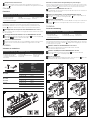
Observe safety notes and torque specifications
Observe the safety notes in the operating instructions R402003540. Tighten the
screws using the torque values specified in the table. Make sure that the
system is not under voltage or pressure.
Mounting the slide attachment kit R402005903/-09/-10/-11
Fasten the attachment (1) using 8 mounting screws (2). Insert the stop screws (3)
into both end faces.
Mounting the shock absorber R402005906/-07/-08
Remove both upper screws from the end cover. Fasten the bracket (4)
with the screws (5). Insert the shock absorber (6).
Exchanging the shock absorber
Use an M5 screw (Not included in the scope of delivery) to fix the position of
the slide. Insert the new shock absorber (6). Turn back the M5 screw slightly.
FRANÇAIS
Fourniture
Respecter les consignes de sécurité et les couples
Respecter les consignes de sécurité figurant dans le mode d’emploi
R402003540. Serrer les vis aux couples indiqués dans le tableau.
Mettre l’installation hors pression et hors tension.
Montage de l’élément de chariot en kit R402005903/-09/-10/-11
Fixer l’élément (1) à l’aide des huit vis de fixation (2). Serrer les deux vis de butée
(3) des faces frontales.
Montage de l’amortisseur à l’aide du kit R402005906/-07/-08
Retirer les deux vis supérieures du couvercle. Fixer le support (4) à l’aide
des vis (5). Insérer l’amortisseur (6).
R402005903/-09/-10/-11 R402005906/-07/-08
1 élément de chariot (1)
8 vis de fixation (2)
2 vis de butée (3)
1 mode d’emploi
1 support (4)
2 vis (5)
1 mode d’emploi
1 amortisseur (6)
(Non compris dans la
fourniture)
A
B
B1
B2
B3, B4
C
C1
C2
A
B
B1
B2
B3, B4
La page est en cours de chargement...
-
 1
1
-
 2
2


AVENTICS Series RTC Mode d'emploi
- Taper
- Mode d'emploi
- Ce manuel convient également à
dans d''autres langues
Documents connexes
-
AVENTICS MSC-20 Le manuel du propriétaire
-
-
-
-
-
-
-
-
-