Riello START AQUA CONDENS 25 BIS NG Manuel utilisateur
- Taper
- Manuel utilisateur

Start Aqua Condens 25 BIS
EN - INSTALLER AND USER MANUAL
FR - MANUEL D’INSTALLATION ET D’UTILISATION
PT - MANUAL DO USUÁRIO E DO INSTALADOR
HU - TELEPÍTÉSI ÉS HASZNÁLATI KÉZIKÖNYV
EL -ΕΓΧΕΙΡΙΔΙΟΕΓΚΑΤΑΣΤΑΤΗΚΑΙΧΡΗΣΤΗ

Start Aqua Condens 25 BIS
2
Start Aqua Condens 25 BIS boiler complies with basic
requirements of the following Directives:
- Regulation (EU) 2016/426
- Efficiency directive: Article 7(2) and Annex III of directive
92/42/EEC
- Electromagnetic compatibility directive 2014/30/EU
- Low-voltage directive 2014/30/EU
- Directive 2009/125/EC Ecodesign for energy-using
appliances
- Directive 2010/30/EU Indication by labelling of the
consumption of energy by energy-related products
- Delegated Regulation (EU) No. 811/2013
- Delegated Regulation (EU) No. 813/2013.
Installer’s - user’s manual ...........................................................4
Boiler operating elements .......................................................104
Hydraulic circuit ......................................................................106
Electric diagrams .................................................................... 109
Circulator residual head.......................................................... 113
EN
The following symbols are used in this manual:
9 CAUTION = operations requiring special care and adequa-
te preparation
a NOT ALLOWED = operations that MUST NOT be
performed
RANGE RATED
This boiler can be adapted to the heating requirements of the system, it is possible to change the maximum output in central heating.
Refer to chapter “Adjustments” for calibration.
After setting the desired output report the value in the table on the back cover of this manual, for future references.
La chaudière Start Aqua Condens 25 BIS respecte les
conditions de base requises par les Règlements suivants:
- Règlement (UE) 2016/426;
- Directive Rendement Article 7(2) et Annex III de la
directive 92/42/CEE
- Directive sur la compatibilité électromagnétique 2014/30/
UE
- Directive sur la basse tension 2014/35/EU
- Directive 2009/125/EC concernant les exigences
d’écoconception applicables aux dispositifs d’énergie
- Directive 2010/30/EU concernant l’étiquetage des
consommations d’énergie des produits liés à l’énergie
- Règlement Délégué (UE) No. 811/2013
- Règlement Délégué (UE) No. 813/2013.
Manuel de l’utilisateur- de l’installateur......................................23
Éléments de fonctionnement de la chaudière .........................104
Circuit hydraulique ................................................................... 106
Schémas électriques ...............................................................109
Hauteur de charge résiduelle ..................................................113
FR
Dans certaines parties du manuel on utilise les symboles:
9 ATTENTION = actions demandant une certaine prudence
et une préparation adéquate
a INTERDICTION = actions NE DEVANT absolument PAS
être exécutées
RANGE RATED
Cette chaudière peut être adaptée aux exigences thermiques du système; en effet il est possible de régler la puissance maximale de
la chaudière pour le fonctionnement en mode chauffage. Se référer au chapitre “Réglages” pour consulter les paramètres de réglage.
Une fois que la puissance a été réglée, transférer la valeur dans le tableau présent sur le couvercle arrière. Pour les contrôles et les
réglages ultérieurs, se référer à cette valeur.
A caldeira Start Aqua Condens 25 BIS é compatível com
asespecicaçõesbásicasdasseguintesDiretivas:
- Regulamento (UE) 2016/426
- Diretiva de rendimento: Artigo 7(2) e no Anexo III da
diretiva 92/42/CEE
- Diretiva de compatibilidade eletromagnética 2014/30/UE
- Diretiva de baixa tensão 2014/35/UE
- Diretiva 2009/125/CE concepção ecológica dos
aparelhos que consomem energia
- Diretiva2010/30/UEIndicaçãopormeiodeetiquetagem
do consumo energético pelos produtos relacionados
com energia
- Regulamento Delegado (UE) n.º 811/2013
- Regulamento Delegado (UE) n.º 813/2013.
Manualdousuário-instalador ....................................................43
Elementosdeoperaçãodacaldeira ........................................104
Circuitohidráulico ....................................................................106
Diagramas eléctricos ...............................................................109
Cabeçalresidualdocirculador ................................................113
PT
Em algumas partes do manual são utilizados os símbolos:
9 ATENÇÃO = paraacçõesqueexigemcautelaespeciale
preparaçãoadequada
a PROIBIDO = paraacçõesqueNÃODEVEMabsolutamen-
te ser executadas
RANGE RATED
Estacaldeirapodeseradaptadaàsespecicaçõesdeaquecimentodosistema,épossívelmodicarasaídamáximanoaquecimento
central.
Consulteocapítulo“Ajustes”paraacalibração.
Apósdenirasaídadesejada,relateovalornatabelanacontracapadestemanual,paraconsultasfuturas.

Start Aqua Condens 25 BIS
2
Start Aqua Condens 25 BIS
3
0476
Start Aqua Condens 25 BISmegfelelazalábbiirányelvek
lényegi követelményeinek:
- 2016/426/EU rendelet
- Hatásfok követelményről szóló 92/42/EGK irányelv 7
cikkely (2) és III melléklet
- 2014/30/EU irányelv az elektromágneses
összeférhetőségről
- 2014/30/EUirányelvakisfeszültségűberendezésekről
- 2009/125/EK irányelv az energiafelhasználó termékek
környezetbaráttervezéséről
- 2010/30/EUirányelvazenergiávalkapcsolatostermékek
energia-fogyasztásánakcímkézésseltörténőjelöléséről
- 811/2013/EUfelhatalmazásonalapulórendelet
- 813/2013/EUfelhatalmazásonalapulórendelet.
HU Telepítésikézikönyv-felhasználóikézikönyv.............................63
Akészülékfunkcionálisrészei .................................................104
Vízkeringetés ........................................................................... 106
Elektromos rajzok ....................................................................109
Keringetőszivattyúmaradékemelőmagassága ......................113
ΟλέβηταςStart Aqua Condens 25 BISσυμμορφώνεται
μετιςβασικέςαπαιτήσειςτωνακόλουθωνΟδηγιών:
- Κανονισμός(ΕΕ)2016/426
- Οδηγίααπόδοσης:Τοάρθρο7(2)καιτουπαραρτήματος
IIIτηςοδηγίας92/42/ΕΟΚ
- Οδηγίαηλεκτρομαγνητικήςσυμβατότητας2014/30/ΕΕ
- Οδηγίαχαμηλήςτάσης2014/35/ΕΕ
- Οδηγία2009/125/ΕΚσχετικάμετονοικολογικόσχεδιασμό
τωνπροϊόντωνπουσυνδέονταιμετηνενέργεια(ErP)
- Οδηγία 2010/30/ΕΕ Για την ένδειξη της κατανάλωσης
ενέργειας και λοιπών πόρων των οικιακών συσκευών
με την επισήμανση και την παροχή ομοιόμορφων
πληροφοριώνσχετικάμεταπροϊόντα
- Κατ’εξουσιοδότησηκανονισμός(ΕΕ)Αρ.811/2013
- Κατ’εξουσιοδότησηκανονισμός(ΕΕ)Αρ.813/2013.
Εγχειρίδιοεγκατάστασης-Εγχειρίδιοχρήσης ............................. 83
Στοιχείαλειτουργίαςτηςσυσκευής ..........................................104
Υδραυλικόκύκλωμα ................................................................106
Ηλεκτρικάδιαγράμματα ...........................................................109
Υπολειπόμενούψοςάντλησηςκυκλοφορητή ..........................113
EL
Σεκάποιασημείατουεγχειριδίουχρησιμοποιούνταιτα
σύμβολα:
9 ΠΡΟΣΟΧΗ = γιαενέργειεςπουαπαιτούνιδιαίτερηπροσο-
χήκαικατάλληληπροετοιμασία
a ΑΠΑΓΟΡΕΥΕΤΑΙ = γιαενέργειεςπουΔΕΝΠΡΕΠΕΙνακά-
νετεσεκαμίαπερίπτωσ
RANGE RATED
ΟλέβηταςαυτόςμπορείναπροσαρμοστείστιςαπαιτήσειςθέρμανσηςτουσυστήματοςΠράγματι,μπορείναρυθμιστείημέγιστηπαροχή
τουλέβηταγιατηλειτουργίαθέρμανσης.Ανατρέξτεστοκεφάλαιο“Ρυθμίσεις”γιατιςρυθμίσειςβαθμονόμησης.
Αφούεπιλεχθείηεπιθυμητήισχύςμεταφέρετετηντιμήστονπίνακαπουπαρέχεταιστοπίσωκαπάκι.
Γιατουςεπόμενουςελέγχουςκαιρυθμίσεις,ανατρέχετεπάνταστηνεπιλεγμένητιμή.
Akézikönyvbenazalábbiszimbólumokszerepelnek:
9 FIGYELEM = megfelelő körültekintést és felkészülést
igénylőtevékenységek
a TILOS = olyan tevékenységek, amelyeket NEM SZABAD
végrehajtani
RANGE RATED
Abojlerarendszerfűtésiigényeihezigazítható.Aközpontifűtésmaximálisteljesítményemódosítható.Abeállításhozlásda“Szabályozás”
részt.
Amegfelelőteljesítménybeállításautánjegyezzefelazértéketakézikönyvhátsóborítójánlévőtáblázatba

Start Aqua Condens 25 BIS
4
ENGLISH
5
EN ENGLISH
INSTALLATION MANUAL
1 - WARNINGS AND SAFETY
9 After removing the packaging, check the integrity and
completeness of the supply and, otherwise, contact the Riello
Agency that sold the boiler.
9 The Start Aqua Condens 25 BIS boiler must be installed by a
qualied company in accordance with the regulations in force,
at the end of the installation process, must issue the owner with
a declaration of conformity certifying that the installation has
been performed according to the best working practices and
in observance of applicable legislation and of the indications
provided by Riello in the present instructions booklet.
9 The installer must instruct the user about the operation of the
appliance and about essential safety regulations.
9 When carrying out routine maintenance, it is always
recommended to check the consumption level of the sacricial
anode.
9 The boiler must be used for the purpose for which it was
expressly built. The manufacturer accepts no liability within or
without the contract for any damage caused to people, animals
and property due to installation, adjustment and maintenance
errors or to improper use.
9 In the event of a water leakage, shut off the water supply and
promptly contact the Technical Assistance Centre or other
professionally qualied personnel.
9 Not using the boiler for an extended period of time involves
the execution of at least the following operations:
- turn the main appliance switch and the main system switch
to "off"
- close the fuel and water taps of the heating system
- drain the heating and domestic hot water circuits if there is
a risk of freezing.
9 The boiler maintenance must be carried out at least once a
year.
9 This booklet and that of the User are an integral part of the
appliance and therefore should be carefully preserved and
should always accompany the boiler even when it is sold to
another owner or user or when transferred to another system.
In case of loss or damage, please contact your local Technical
Assistance Centre for a new copy.
9 This appliance should not be operated by children younger
than 8 years, people with reduced physical, sensory or men-
tal capacities, or inexperienced people who are not familiar
with the product, unless they are given close supervision or
instructions on how to use it safely and are made aware by a
responsible person of the dangers its use might entail. Chil-
dren must not play with the appliance. It is the user’s respon-
sibility to clean and maintain the appliance. Children should
never clean or maintain it unless they are given supervision.
9 The boiler is constructed so as to protect both the user and
the installer from any accidents. After each intervention on the
product, pay special attention to the electrical connections,
especially the stripped parts of the wires, which must not
protrude from the terminal board in any way.
9 Dispose of all the packaging materials in the suitable
containers at the corresponding collection centres.
9 When disposing of waste, be careful not to harm human
health or employ procedures or methods which may damage
the environment.
At the end of its life, the product should be not be disposed of
as solid urban waste, but rather it should be handed over to a
differentiated waste collection centre.
Remember that the use of products requiring fuels, electricity and
water necessitates the respect of certain basic safety rules such as:
0 it is forbidden to activate electric devices or appliances such
as switches, household appliances and so on if you notice a
smell of fuel or unburnt fuel;
0 in this case:
- ventilate the room by opening the doors and windows
- close the fuel shut-off device
- promptly call the Technical Assistance Centre or
professionally qualified personnel;
0 it is forbidden to touch the boiler while barefoot or if parts of
your body are wet;
0 it is forbidden to carry out any cleaning operations before
disconnecting the boiler from the electricity supply; to do this,
turn the main system switch to “OFF”;
0 it is forbidden to modify safety and adjustment devices without
the boiler manufacturer's permission and relative instructions;
0 it is forbidden to pull, detach or twist the electric cables that
emerge from the boiler, even if the boiler itself is disconnected
from the mains supply;
0 it is forbidden to plug or reduce the size of any openings used
for airing the installation area;
0 it is forbidden to leave ammable containers and substances
in the room where the boiler is installed;
0 it is forbidden to disperse and leave packaging material within
children's reach as it may be a potential source of hazard;
0 it is forbidden to obstruct the condensate outlet.
2 - DESCRIPTION
Start Aqua Condens 25 BIS is a wall-hung condensing boiler, with
premix burner and low emission of pollutants for heating and for the
production of DHW use and has a 45 litre steel storage tank.
This is an electronically controlled boilers with automatic ignition,
ionisation flame check and with proportional control system of the
gas and air flows, both in heating and DHW.
It uses an aluminium alloy boiler body, has a sealed combustion
chamber and, based on the gas discharge accessory used, is
classified in categories B23P, B53P, C13-C13x, C33-C33x, C43-
C43x, C53-C53x, C63-C63x, C83-C83xC93C93x. The switching of
the heating and DHW modes is performed via a three-way electric
valve which set on DHW when in the rest position. To guarantee the
correct water output in the exchanger, the boiler is equipped with
an automatic by-pass.
The Start Aqua Condens 25 BIS boiler is also equipped with:
- Range Rated - this means the boiler is equipped with a device
that adapts it to the heat requirements of the system, so the
boiler output can be adjusted according to the energy needs of
the building.
- Circulator anti-blocking.
- First-level antifreeze (suitable for indoor installations).
- 8 litre expansion tank.
- 2 litre DHW expansion tank.
- Digital display indicating the operating temperature and alarm
codes.
- Pre-mix low emissions burner.
- Continuous electronic flame modulation for domestic hot water
and heating.
- Premix combustion system which ensures a constant air-gas
ratio.
- Anti-legionella: Legionella is a disease that can be contracted
by inhaling small droplets of water (aerosols) which contain the
Legionella bacteria (bacteria occurs naturally in lakes and rivers
all over the world). The decimation of the bacterium is obtained
by taking the stored water to a temperature over 50/55° C.
It is therefore recommended to position the DHW temperature
selection knob to maximum at least every 2/3 days, taking the
temperature of the stored water to 60° C, and maintaining this
temperature for a minimum time of 5 minutes.
- Ambient thermostat or programmable timer, remote control or
local valve prearrangement.

Start Aqua Condens 25 BIS
4
ENGLISH
5
- Provision for external probe connection that enables the climate
control function.
- Prepared for limit thermostat on reduced temperature systems.
- Self-diagnostics for signalling the cleaning of the primary circuit
heat exchanger.
2.1 Safety devices
The Start Aqua Condens 25 BIS boiler is equipped with the
following safety devices:
- Safety valve that intervenes in the event of excessive hydraulic
pressure (max 3 bar).
- Water circuit diagnosis which safeguards the boiler in the
event of insufficient circulation or lack of water. The electronics
of the boiler, by comparing the temperature read by the outlet
and return sensors (circulation analysis) and the rise rate of
the output temperature (no water analysis) ensures the safety
lockout of the appliance.
- Flue gas probe: this intervenes (putting the boiler in safety stop
mode) if the temperature of the combustion products exceeds
the maximum operating temperature of the discharge pipes.
- Flue gas safety evacuation system incorporated in the
pneumatic operation of the gas valve subject to the premix
burner. The gas valve is opened based on the quantity of air
pushed by the fan. This implies that, if the flue gases exhaust
circuit is blocked, the air flow is cancelled and the valve does
not have the ability to open. Furthermore, the float present in
the siphon prevents any passage of the flue gases from the
condensation discharge.
- Condensate discharge obstruction safety device that
via a condensate level sensor blocks the boiler if the level of
condensate in the heat exchanger exceeds the limit allowed.
- Over-temperature safety device on both the delivery and return
lines, with dual probe (limit temperature 95°C).
9 The intervention of the safety devices indicates a boiler
malfunction, therefore immediately contact the Technical
Assistance Centre.
9 The boiler must not be put in service, even temporarily, with
non-operating or tampered safety devices.
9 The safety devices must be replaced by the Technical
Assistance Centre, using exclusively original manufacturer
components.
After carrying out the repair, perform an ignition test.
2.2 Circulator
The residual discharge head for the heating system in terms of flow
rate is outlined in the graph (fig. 1-2).
The heating system pipes must be dimensioned bearing in mind
the residual discharge head available.
Note that the boiler is working properly if the heat exchanger for
heating has sufficient water circulation. For this reason, the boiler
is fitted with an automatic by-pass that sets the correct flow rate for
the water in the heat exchanger for heating in any system condition.
The boilers are equipped with an anti-blocking system which starts
up an operation cycle after every 24 hours of stop, with the mode
selector in any position.
9 The “anti-locking” function is only activated when the boiler is
electrically powered.
0 It is strictly forbidden to operate the circulator without water.
2.3 Circulator signals
With power supply present, the green coil is steady and the
circulator operates at the maximum allowed.
Presence of anomalies
The icon is steady red; the anomaly could be attributable to:
low power supply voltage
circulator blocked
electronic anomaly.
Check the power supply voltage (presence and value); if the cicrulator
is blocke, proceed with the manual release operation (see “Manual
reset of the circulator”); if the anomaly persists, replace the circulator.
No
communication
C
ommunication
:
LIN/MOD/PWM
10 flashes per sec.
Alarm
status
Anomaly
Block/
electronic anomaly
2.4 Manual reset of the circulator
The circulator has an electronic reset function, however if a manual
reset is necessary, proceed as follows:
- use a Phillips screwdriver, preferably Phillips no. 2,
- insert the screwdriver in the hole until it comes into contact with
the reset screw, then press (basically the screw should go in by
about 2 mm) and turn anti-clockwise.
3 - INSTALLATION
3.1 Receiving the product
The Start Aqua Condens 25 BIS boiler is supplied in a single pack
protected by cardboard packaging.
The boiler is supplied as standard with the following material:
- instruction booklet for the installer and user
- bar code labels
- supporting cross-member
- package with hydraulic fittings.
9 The instruction booklets are an integral part of the boiler and
there it is recommended to read them carefully and keep them
in a safe place.
3.2 Dimensions and weights (fig. 3)
Start Aqua Condens 25 BIS
L 600 mm
P 450 mm
H 940 mm
net weight 66 kg
3.3 Handling
After unpacking, handling of the boiler is done manually using the
support frame (fig. 4).
3.4 Installation room
In configuration C, the appliance can be installed in any type of
room and there are no limitations due to ventilation conditions
or room volume since the Start Aqua Condens 25 BIS boiler
has an "airtight" combustion circuit in relation to the installation
environment.
In configuration B23P, B53P the appliance cannot be installed in
bedrooms, bathrooms, showers or where there are open fireplaces
without a proper air flow. The room where the boiler is installed
must have proper ventilation.
9 Consider the clearances necessary to access safety and
adjustment devices and to perform maintenance operations.
9 Check that the electric protection level of the appliance is
suitable for the installation room characteristics.
9 If the boilers are supplied with fuel gas of a specic weight
greater than that of the air, the electric parts will have to be
positioned more than 500mm above ground level.

Start Aqua Condens 25 BIS
6
ENGLISH
7
3.5 Installation on appliances that are old or that
need to be updated
When the Start Aqua Condens 25 BIS boiler is installed in old
systems or systems being updated, verify that:
- The smoke pipe is suitable for the temperature of the combustion
products with condensation, calculated and built according to
Standard, is as straight as possible, airtight, insulated and has
no blockages or narrow sections. It is equipped with appropriate
condensate collection and discharge systems
- The electrical system is installed in compliance with the specific
standards and by qualified personnel
- The fuel supply line and eventual tank (LPG) are made according
to specific Standards
- The expansion tank ensures the total absorption of the dilatation
of the fluid contained in the system
- The flow rate and head of the circulator are suitable to the
characteristics of the system.
- The system has been washed and cleaned of mud and grime, de-
aerated and water tight. It is recommended to install a magnetic
filter on the return of the system.
- The boiler condensate drain system (siphon) is connected and
routed to the collection of "white" water.
9 The manufacturer is not liable for any damage resulting from
the incorrect construction of the ue gas discharge system.
9 The ue gas discharge pipes for condensing boilers are made
of special materials that are different compared to those made
for standard boilers.
3.6 Boiler installation
For correct installation, keep in mind that (fig. 5):
- the boiler must not be placed above a stove or other cooking
appliance
- it is forbidden to leave inflammable products in the room where
the boiler is installed
- heat-sensitive walls (e.g. wooden walls) must be protected with
proper insulation
- the minimum clearances for technical and maintenance
interventions must be respected.
The boiler is supplied with a pre-assembly template which allows
for realising the connections to the heating and domestic hot water
system without the boiler, which may be subsequently assembled,
standing in the way. Connect the discharge manifold to a suitable
discharge system (for details, see chapter "Discharge manifold").
FIXING OF THE PRE-ASSEMBLY TEMPLATE
The Start Aqua Condens 25 BIS boiler is designed and built to be
installed in heating and domestic hot water systems.
The position and dimension of hydraulic fittings are shown in the
drawings (fig. 6).
- Position the plate with the aid of a spirit level: check the correct
horizontal plane and the planarity of the boiler rest surface; make
it thicker if needed.
- Trace the fixing points.
- Remove the template and carry out the drilling.
- Fix the plate to the wall using appropriate plugs.
- Check the correct horizontality with a spirit level.
FIXING THE BOILER
- Hook the boiler to the brackets on the plate.
3.7 Hydraulic connections (fig. 7-8-9)
Connect the fittings and gaskets supplied with the system.
We recommend connecting the boiler to the systems introducing
both the DHW shut-off valve as well as the shut-off valves for the
heating system; for this purpose a heating system valves kit and
heating valves kit with filter is available.
Connect brass taps supplied to the fittings and the boiler.
9 The selection and the installation of the system components are
the responsibility of the installer, who must operate according
to the rules of good technique and current Legislation.
9 A carrying case kit is available that allows to make connections
quickly and without unnecessary waste on each system.
M Heating delivery 3/4”
R Heating return line 3/4”
G Gas 3/4”
SC Discharge manifold
AF Cold water inlet 1/2”
AC Hot water outlet 1/2”
3.8 Discharge manifold
The discharge manifold collects: condensate water, any evacuation
water from the safety valve and the system discharge water (fig. 10).
9 The manifold must be connected via a rubber pipe (not
provided) to an appropriate collection and evacuation system
in the white water discharge drain in compliance with current
regulations. The outer diameter of the manifold is 20 mm: it is
therefore advisable to use a rubber pipe ø18-19 mm closed
with a suitable clamp (not provided).
9 Regularly check that the discharge manifold is not blocked by
solid residues that might prevent the outow of condensate
water.
9 The manufacturer is not liable for any damage resulting from
the failure to channel the condensate.
9 Sealing of the condensate drainage connection line must be
guaranteed.
9 The boiler manufacturer is not responsible for any oods
caused by the intervention of the safety valves.
3.9 Installing the external probe (accessory)
The correct operation of the external probe is fundamental for the
good operation of the climatic control.
INSTALLING AND CONNECTING THE EXTERNAL PROBE
The probe must be installed on an external wall of the building to be
heated, observing the following indications:
- it must be mounted on the side of the building most often exposed
to winds (the NORTH or NORTHWEST facing wall), avoiding
direct solar irradiation;
- it must be mounted about 2/3 of the way up the wall;
- it must not be mounted near doors, windows, air outlet points, or
near smoke pipes or other heat sources.
The electrical wiring to the external probe is made with a bipolar
cable with a section from 0.5 to 1 mm2 (not supplied), with a
maximum length of 30 metres. It is not necessary to respect the
polarity of the cable when connecting it to the external probe. Avoid
making any joints on this cable however; if joints are absolutely
necessary, they must be watertight and well protected.
Any ducting of the connection cable must be separated from live
cables (230V AC).
FIXING THE EXTERNAL PROBE TO THE WALL
The probe must be fixed on a smooth part of the wall; in the case
of exposed brickwork or an uneven wall, look for the smoothest
possible area (fig. 11).
- Loosen the plastic upper protective cover by turning it
anticlockwise.
- After deciding on the best fixing area of the wall, drill the holes
for the 5x25 wall plug.
- Insert the plug in the hole.
- Remove the card from its seat.
- Fix the box to the wall, using the screw supplied.
- Attach the bracket, then tighten the screw.
- Loosen the nut of the cable grommet, then insert the probe
connection cable and connect it to the electric clamp.
To make the electrical connection between the external probe and
the boiler, refer to the “Electrical wiring” chapter.
9 Remember to close the cable grommet well, to prevent any air
humidity getting in through the opening.
- Put the board back in its seat.
- Close the plastic upper protective cover by turning it clockwise.
Tighten the cable grommet very well.
3.10 Electrical wiring
The Start Aqua Condens 25 BIS boiler leaves the factory
completely wired and only need to be connected to the mains
power supply (using the supplied power cable) and the ambient
thermostat (TA) and/or timer, via relevant terminals.
- Set the system's main switch to "off"
- Loosen the screws (B) that hold the housing in place (fig. 12)
- Move the base of the shell forward and then upwards in order to
free it from the frame (fig. 13)
- Turn the instrument panel forward

Start Aqua Condens 25 BIS
6
ENGLISH
7
- Unscrew the two screws of the small cover on the electronic
board to have access to the terminals (fig. 14).
9 Safety low voltage ambient thermostat input (clean contact).
9 In case of power supply between phases, check with a tester
which of the two wires has a greater potential in relation to
the earth and connect it to the L and similarly connect the
remaining wiring to the N.
9 The earth conductor must be a couple of cm longer than the
others.
9 The boiler can operate with a phase-neutral or phase-phase
supply.
9 Mandatory items:
- use an omnipolar magnetothermic switch, feeder
disconnector, compliant with CEI-EN 60335-1 standards
(contact opening of at least 3.5mm, category 3)
- use cables with a section ≥ 1.5mm2 and comply with the
connection L (phase) - N (Neutral)
- the switch amperage must be adapted to the electric output
of the boiler, refer to technical data to check the electric
output of the model installed
- connect the appliance to an effective grounding system
- safeguard access to the power socket after the installation
0 It is forbidden to use gas and water pipes for grounding the
unit.
9 The manufacturer is not liable for any damage caused by
failure to comply with the wiring diagrams.
9 The installer is responsible for ensuring the appliance is
suitably earthed; the manufacturer will not be liable for any
damage resulting from an incorrect or absent earth connection.
3.11 Boiler configuration
The electronic board has a number of jumpers (JPX) that allow to
configure the boiler.
To access the board, proceed as follows:
- set the main system switch to OFF
- loosen the screws (B) that hold the housing in place (fig. 12)
- move the base of the shell forward and then upwards in order to
free it from the frame (fig. 13)
- turn the instrument panel forward
- unscrew the two screws of the small cover on the electronic
board to have access to the terminals (fig. 14).
JUMPER JP7: pre-selection of the most appropriate heating
temperature adjustment field based on the type of system.
Jumper not inserted - standard system: standard system 40-80 °C
Jumper inserted - floor system: floor installation 20-45°C.
During manufacture, the boiler is configured for standard systems
(fig. 15).
JP1 Calibration (Range Rated)
JP2 Heating timer reset
JP3 Calibration (see paragraph “Adjustments”)
JP4 Jumper on. Do not modify.
JP5 Jumper on. Do not modify.
JP6 Enable night-time compensation and continuous pump
function (only with outdoor probe connected)
JP7 Enable standard system/low temperature
management (see above)
JP8 No jumper. Do not modify.
3.12 Gas connection
The connection of the Start Aqua Condens 25 BIS boiler to the gas
supply must be carried out in compliance with current installation
standards.
Before carrying out the connection, it is necessary to ensure that:
- the gas type is suitable for the appliance
- the piping is thoroughly clean.
9 The gas feeding system must be adapted to the boiler output
and must be equipped with all the safety and control devices
prescribed by the current standards. the use of a lter of
adequate dimensions is recommended.
9 Once the installation is done, check that the junctions carried
out are sealed.
3.13 Flue gas outlet and combustion air suction (fig.
16-17-18-19-20)
The Start Aqua Condens 25 BIS boiler must be equipped with
adequate flue gas outlet and air suction pipes according to the
type of installation, to be chosen from those indicated in the Riello
catalogue.
9 For the maximum lengths of the ducts refer to ue systems
available in the catalogue.
9 The straight length measurement is inclusive of the rst bend
(boiler connection), terminals and joints; with the exception
of the vertical coaxial duct Ø 60-100 mm, where the straight
length does not include the bends.
(TYPE B23P-B53P) INSTALLATION
Flue gas discharge pipe ø 80mm
The flue gas outlet pipe can be directed to the most suitable
direction according to installation requirements.
For installation, follow the instructions supplied with the kit.
In this configuration, the boiler is connected to the flue gas outlet
pipe of ø 80 mm through an adaptor of ø 60-80 mm.
9 In this case, the combustion air is picked up from the boiler
installation room (which must be a suitable technical room
with proper ventilation).
9 The non insulated ue gas outlet pipes are potential sources
of danger.
9 Make sure the ue gas discharge pipe is tilted 3° towards the
boiler.
maximum length of the flue gas
discharge pipe ø 80mm
pressure drop
45° curve 90° curve
60 m 1 m 1,5m
9 "Straight length" means without bends, drainage terminals or
joints.
“AIRTIGHT” INSTALLATION (TYPE C)
The boiler must be connected to concentric or twin flue gas
discharge pipes and air suction pipes, both leading outdoors. The
boiler must not be operated without them.
Concentric pipes (ø 60-100mm)
The concentric pipes can be fitted in most suitable direction in
relation to installation requirements.
9 It is compulsory to use specic pipes (see Riello catalogue).
9 Make sure the ue gas discharge pipe is tilted 3° towards the
boiler.
9 Non-insulated outlet pipes are potential sources of danger.
9 The boiler automatically adapts ventilation according to the
type of installation and the length of the duct. Do not obstruct
or choke the combustion air suction pipe in any way.
HORIZONTAL
straight length of concentric
pipe Ø 60-100 mm
pressure drop
45° curve 90° curve
7,85 m 1,3m 1,6m
VERTICAL
straight length of concentric
pipe Ø 60-100 mm
pressure drop
45° curve 90° curve
8,85 m 1,3m 1,6m
For installation, follow the instructions supplied with the specic
accessory kit for condensing boilers.
9 Straight length means without bends, drainage terminals or
joints.
9 The use of a longer pipe causes a loss of output of the boiler.

Start Aqua Condens 25 BIS
8
ENGLISH
9
Concentric pipes (ø 80-125)
The appropriate adaptor kit must be installed for this configuration.
The concentric pipes can be fitted in most suitable direction in
relation to installation requirements. For installation, follow the
instructions supplied with the specific kit for condensing boilers.
straight length of concentric
pipe Ø 80-125 mm
pressure drop
45° curve 90° curve
14,85 m 1 m 1,5m
9 "Straight length" means without bends, drainage terminals or
joints.
Twin pipes (ø 80mm)
The twin pipes can face in the direction most suited to the installation
requirements.
The suction pipe of the combustion air must be connected to the
input after removing the cap fixed with three screws.
The flue gases discharge pipe must be connected to the flue gases
outlet.
For installation, follow the instructions supplied with the specific
accessory kit for condensing boilers.
straight length of twin pipes ø 80mm pressure drop
45° curve 90° curve
36+36 m 1 m 1,5m
9 "Straight length" means without bends, drainage terminals or
joints.
9 The use of a longer pipe causes a loss of output of the boiler.
9 It is compulsory to use specic pipes (see Riello catalogue).
9 Make sure the ue gas discharge pipe is tilted 3° towards the
boiler.
9 The boiler automatically adapts the purging to the type of
installation and the length of the pipes. Do not obstruct or
choke the pipes in any way.
9 For the indication of the maximum lengths of the single pipe,
refer to the charts.
POSSIBLE OUTLET CONFIGURATIONS (g. 21)
B23P-B53P Suction in room, with external outlet
C13-C13x Concentric wall outlet. The pipes may also be split,
but the outputs must be concentric or sufficiently
close together to be subjected to similar wind con-
ditions (within 50cm)
C33-C33x Concentric roof outlet. Outlets as for C13
C43 C43x Discharge and suction in separate shared smoke
pipes subject to similar wind conditions
C53-C53x Separated discharge and suction on wall or roof,
in areas with different pressure levels
C63-C63x Discharge and suction lines using pipes marketed
and certified separately (1856/1)
C83 C83x Outlet in single or shared smoke pipe and wall
suction line.
C93-C93x Discharge on roof (similar to C33) and air suction
via a single existing smoke pipe.
9 Refer to the regulations in force.
3.14 System loading and emptying (fig. 22-23)
FILLING THE SYSTEMS
In case of a new installation or replacement of the boiler, it is
necessary to clean the heating system. In order to ensure the
proper functioning of the product, after any cleaning, additive and/
or chemical treatments (e.g. antifreeze liquids, filming agents, etc.)
check that the parameters in the table are within the indicated values.
Parameters unit of
measurement
Hot water
circuit
Filling
water
pH value - 7-8 -
Hardness °F - <15
Appearance - - clean
Fe mg/kg 0,5 -
Cu mg/kg 0,1 -
Once the hydraulic connections have been carried out, fill the
system. This operation must be carried out with a cold system,
following these instructions:
Domestic hot water system:
- open the cold water inlet tap to fill the storage tank
- to check that the storage tank is full, open a hot water tap and
wait for the water to exit.
Heating system:
- make sure that the system discharge valve (B) is closed
- open the plug of the automatic bleed valves (C and E) by two or
three turns
- open the filling tap (G) until the pressure indicated by the water
pressure gauge is 1,5 bar.
- open the manual bleed valve (D) with a CH11 wrench and close
it once the bleeding procedure is completed; If necessary, repeat
this operation until no more air exits the valve (D)
- once the filling operation of the system is finished, close the filling
tap G.
Each time the boiler is electrically powered, it begins an automatic
venting cycle that lasts about 2 minutes. The symbol “ ” is
displayed during this phase.
NOTE: the venting of the boiler takes place automatically via the
two automatic bleed valves C and E.
NOTE: the first system filling operation must be done by means of
tap G.
EMPTYING THE SYSTEMS
Before starting emptying, switch off the electrical supply by turning
off the system's main switch
Heating system:
- close the shut-off
devices of the heating system
- open the automatic bleed valve (C)
- manually loosen the system drain valve (B), keeping the elbow of
the hose in position to prevent it slipping from its seat
- the system's water is discharged through the discharge manifold (A)
- drain the lowest points of the system.
Domestic hot water system
When there is risk of frost, the domestic hot water system must be
emptied in the following way:
- turn off the main water supply tap
- unscrew the plug on the hose connection (F)
- connect a plastic pipe to the hose connection of the storage tank
discharge valve (F)
- release the discharge device of the valve
- turn on all the hot and cold water taps
- drain the lowest points of the system.
9 The discharge manifold (A) must be connected via a rubber
pipe to an appropriate collection and evacuation system in
the white water discharge drain in compliance with current
regulations. The outer diameter of the manifold is 20 mm: it is
therefore advisable to use a rubber pipe Ø18-19 mm closed
with a suitable clamp (not provided). The manufacturer is not
liable for any damage resulting from the failure to channel the
condensate.
Eliminating the air from the heating circuit and boiler (fig. 24)
During the initial installation phase, or in the event of a maintenance,
you are advised to perform the following sequence of operations:
- Switch off the power supply to the boiler.
- Using a CH11 spanner open the manual air vent valve located
above the air box; the tube supplied with the boiler must be
connected to the valve to let out the water into an outside
container.
- Turn on the system filling tap on the hydraulic unit and wait until
the water starts coming out of the valve. Make sure that it comes
only water.
- Close the manual air vent valve with the CH11 spanner.
- Turn off the system filling tap when the water pressure indicated
by the hydrometer reaches 1-1.5 bar.

Start Aqua Condens 25 BIS
8
ENGLISH
9
- Switch on the power supply to the boiler leaving the boiler in OFF
mode. Check that the gas tap is closed.
- The boiler, now, starts the vent cycle. Perform it by checking
that there is no air inside the boiler and that the pressure does
not drop too much (otherwise repeat the operations described
above).
- Turn on the gas tap and ignite the boiler.
4 - COMMISSIONING AND MAINTENANCE
4.1 First commissioning preparation
Before the ignition and the functional testing of the Start Aqua
Condens 25 BIS boiler, it is necessary to:
- check that the system fuel and water supply taps are open
- check that the gas type and the power supply pressure are those
for which the boiler is designed
- make sure the cap on the vent valve is open
- check on the display that the pressure of the water circuit when
cold is between 1 bar and 1.5 bar and that the circuit is vented
- check that the pre-loading of the expansion tank is adequate
(see the "Technical data" table)
- check that the electrical connections have been carried out
correctly
- check that the combustion product outlet and air suction pipes
were adequately realised
- check that the circulator turns freely; undo the inspection screw
and check with a flat screwdriver that the rotor shaft moves
without hindrances.
9 Before loosening or removing the closing tap of the circulator,
protect the underlying electrical devices from possible water
leakage.
4.2 Control prior to commissioning
9 The rst time you turn the boiler on and in case of maintenan-
ce work, before using the appliance you must ll the siphon
with water and make sure that the condensation is evacuated
correctly.
Fill the condensation collection siphon pouring 1 litre of water into
the boiler combustion-analysis outlet with the boiler off, and check
that:
the safety cut-off device is oating
water is owing correctly from the discharge pipe out of the boiler
the condensate outlet connection line is watertight.
If the condensate outlet circuit (siphon and pipes) is working cor-
rectly, the condensation level will not exceed the maximum.
Filling the siphon before using the appliance, and the use of a sa-
fety cut-off device inside the siphon, prevent exhaust gases from
being released into the environment.
Repeat during standard and non-standard maintenance work.
~15 mm
MAX
-
4.3 First commissioning
- Adjust the ambient temperature thermostat to the desired
temperature (~20°C) or, if the system is equipped with a
programmable thermostat or timer, ensure that the thermostat or
timer is "active" and set correctly (~20°C)
- A variety of information appears on the display for each power
supply, including the value of the flue gases probe meter (-C- XX
- see "Display and fault codes" - Fault A 09), the boiler will then
start an automatic venting cycle of about 2 minutes
- The display shows the symbol
To stop the automatic venting cycle, proceed as follows:
- access the electronic board by removing the housing, turning the
instrument panel forwards you and opening the terminal board
cover.
Then:
- press the CO button.
9 Live electrical parts (230 Vac).
CN8
CN7
1
12
CN11
1
4
CN10
1
7
CN9
CN6 CN5
CN12
1
CN4
1
3
CN3
1
2
CN2
1
6
AKL
CN1
1
FA1
FA2
JP1
JP2
JP3
JP4
JP5
JP6
JP7
JP8
CN15
P3
P2
P1
CN13
CN14
SW1
P4
F1
3.15A T
CO button
To start up the boiler it is necessary to carry out the following
operations:
- power the boiler
- turn on the gas tap to allow fuel flow
- adjust the ambient thermostat to the required temperature
(~20°C).
Turn the mode selector to the required position:
Winter mode
Turn the function selector to within the adjustment range. The
boiler produces domestic hot water and heating water. The boiler
lights automatically in response to a heat request. The digital
display indicates the heating water temperature. The boiler lights
automatically in response to a request for domestic hot water. The
display indicates the domestic hot water temperature.
WINTER MODE

Start Aqua Condens 25 BIS
10
ENGLISH
11
Adjustment of the heating water temperature
To adjust the heating water temperature, turn the mode selector to
within the adjustment range (turn clockwise to increase the value
and anticlockwise to reduce the value).
Depending on the type of system, the most suitable temperature
range can be pre-selected:
- standard systems 40-80 °C
- floor installations 20-45°C.
For details see paragraph “Boiler configuration”.
HEATING WATER
TEMPERATURE
DOMESTIC HOT WATER
TEMPERATURE
Adjusting the heating water temperature with an external
probe connected
When an external probe is installed, the delivery temperature
is automatically selected by the system, which quickly adjusts
the ambient temperature according to variations in the outside
temperature. If you want to alter the temperature value (increasing
or reducing the value automatically calculated by the electronic
card), use the heating water temperature selector: turn it clockwise
to increase the temperature, or anticlockwise to reduce it. The
correction possibility is between 15° C and 25° C levels of comfort
(0 = 20° C), shown on the digital display by rotating the knob.
Summer mode
The standard domestic hot water-only mode is activated by
turning the selector to the summer symbol . The boiler lights
automatically in response to a request for domestic hot water. The
digital display indicates the delivery temperature.
SUMMER MODE
Adjustment of the domestic hot water temperature
To adjust the domestic hot water temperature (for baths, showers,
kitchen etc.), turn the dial with the symbol clockwise to increase
the value, or anticlockwise to decrease the value (min. value 37°C -
max. value 60 °C). The boiler is in standby until the burner switches
on following a heat request. The boiler continues to function until
the temperatures set on the boiler are reached, or the heat request
terminates; it will then go back to standby. In the case of a temporary
stop the digital display shows the fault code.
ADJUSTING THE DOMESTIC HOT WATER TEMPERATURE
Heating Temperature Control function (C.T.R.)
Turn the heating water temperature selector into sector highlighted
with white markers to activate the C.T.R. self-adjusting system:
depending on the temperature set on the ambient thermostat and
the time taken to reach it, the boiler automatically varies the heating
water temperature by reducing operating time, thereby achieving
increased comfort and energy savings.
C.T.R. FUNCTION
Reset function
To restore normal operation, turn the function selector to off, wait
5-6 seconds, and then turn it to the required position. At this point,
the boiler will restart automatically.
NOTE: If the attempts to reset the appliance do not activate
operation, contact the Technical Assistance Centre.
RESET FUNCTION
4.4 Checks during and after the first commissioning
Following commissioning, check that the Start Aqua Condens
25 BIS, boiler performs the start-up procedures and subsequent
shutdown properly by acting on the:
- mode selector
- calibration of the heating water temperature selector and
domestic hot water temperature selector
- requested ambient temperature (by intervening on the ambient
thermostat or programming timer).
Also check the domestic hot water operation by opening a hot
water tap with the mode selector both in summer mode and in
winter mode.
Check the full stop of the boiler by turning off the system's main
switch.
After a couple of minutes of continuous operation to be obtained
by turning on the system's main switch, the mode selector on
(summer) and by keeping open the domestic hot water device, the
binders and manufacturing waste evaporate and it will be possible
to perform:
- the supply gas pressure check
- the combustion check.
Supply gas pressure check
- Turn the mode selector to to turn off the boiler

Start Aqua Condens 25 BIS
10
ENGLISH
11
- Undo the screws (B) that fasten the shell
B
- Move the housing base forwards and then upwards to unhook it
from the frame
- Turn the instrument panel forward
- Undo by two turns the screw of the pressure test point upstream
from the gas valve and connect the pressure gauge
Pressure test point
upstream of the
valve
- Power the boiler electrically by setting the main system switch
to “ON”
- Bring the mode selector to summer
- Turn the DHW temperature selector to maximum. Make sure that
the water in the storage tank is not at temperature
- Fully open the hot water tap
- With the burner at maximum output, check that the gas pressure
is comprised between the minimum and rated power supply
pressure values indicated in the table
- Turn off the hot water tap
- Disconnect the pressure gauge and tighten the pressure test
point screw again upstream from the gas valve.
Combustion check
To carry out the combustion analysis, proceed as follows:
- turn the mode selector to to turn off the boiler
- turn the DHW adjustment selector to the combustion analysis
mode position
- wait for the burner to fire (approx. 6 seconds). “ACO” is displayed
and the boiler operates at the maximum heating output
- remove the screw and the cover on the air distribution box (see
image below)
- insert the flue gas analysis probe into the sockets provided on
the air box
- check that the CO2 values correspond to those indicated in the
"Technical data" table, if the value displayed is different, modify
as indicated in chapter "Gas valve calibration"
- perform the combustion check.
cover
screw
Then:
- remove the analyser probe and close the combustion analysis
sockets with the screw.
9 The ue gas analysis probe should be inserted until its
reaches the stop.
9 Even during the combustion analysis phase, the function that
switches the boiler off when the water temperature reaches
the maximum limit (about 90°C) remains enabled.
When the checks are completed:
- position the mode selector depending on the operating mode
desired
- adjust the selectors according to the client's requirements.
9 The boiler is supplied for use with methane gas (G20) and are
already factory set as specied on the rating plate, so do not
require any calibration.
9 All checks must be carried out exclusively by the Technical
Assistance Centre.
4.5 Setting the thermoregulation
Thermoregulation only works with external sensor connected, so
once installed, connect the outdoor probe - accessory on request -
to the appropriate connections provided on the terminal board of the
boiler. This enables the THERMOREGULATION function.
Choice of the compensation curve
The compensation curve for heating maintains a theoretical
temperature of 20°C indoors, when the external temperature is
between +20°C and -20°C. The choice of the curve depends on
the minimum external temperature envisaged (and therefore on the

Start Aqua Condens 25 BIS
12
ENGLISH
13
geographical location), and on the delivery temperature envisaged
(and therefore on the type of system). It is carefully calculated by
the installer on the basis of the following formula:
KT = T.outlet envisaged - Tshift
20- min. design external T.
Tshift = 30°C standard system
25°C floor installations
If the calculation produces an intermediate value between two
curves, you are advised to choose the compensation curve nearest
the value obtained.
Example: if the value obtained from the calculation is 1.3, this is
between curve 1 and curve 1.5. Choose the nearest curve, i.e. 1.5.
Selection of the KT must be made by acting on the P3 trimmer on
the card (see multi-wire electrical diagram).
To access P3:
- remove the housing
- turn the instrument panel forward
- undo the fixing screws of the terminal board cover
- unhook the board cover.
9 Live electrical parts (230 Vac).
The settable KT values are as follows:
- standard system: 1.0-1.5-2.0-2.5-3.0
- floor installation: 0.2-0.4-0.6-0.8
and appear on the display for a duration of about three seconds
after the rotation of trimmer P3.
TYPE OF HEAT REQUEST
If an ambient thermostat is connected to the boiler
(Jumper JP6 not inserted)
The heat request is made by the closure of the room thermostat
contact, while the opening of the contact produces a switch-off.
The delivery temperature is automatically calculated by the boiler,
although the user may interact with the boiler. Using the interface
to modify the HEATING, you will not have the HEATING SET-
POINT value available, but a value that you can set as preferred
between 15 and 25°C. The modification of this value will not directly
modify the delivery temperature, but will automatically affect the
calculation that determines the value of that temperature, altering
the reference temperature in the system (0 = 20°C).
If a programming timer is connected to the boiler
(JUMPER JP6 inserted)
With the contact closed, the heat request is made by the delivery
probe, on the basis of the external temperature, to obtain a nominal
ambient temperature on DAY level (20°C). The opening of the
contact does not produce a switch-off, but a reduction (parallel
translation) of the climatic curve on NIGHT level (16°C).
This will activate the night time function.
THERMOREGULATION CURVES
Temperatura esterna (˚C)
Temperatura di mandata (˚C)
20
30
40
50
60
70
80
90
100
-20
0,2
0,4
0,6
0,
8
1,0
1,5
2,02,53,0
T80
T45
-15-10-505101520
T80
- std heating system maximum setpoint temperature
(jumper pos. 1 not inserted).
T45 - oor heating system maximum setpoint temperature
(jumper pos. 1 inserted).
9
The display shows the value of the curve multiplied by 10
(e.g.. 3.0 = 30)
DELIVERY TEMPERATURE (°C)
OUTSIDE TEMPERATURE (°C)
DELIVERY TEMPERATURE (°C)
OUTSIDE TEMPERATURE (°C)
CLIMATIC CURVE CORRECTION
20°C
25°C
15°C
10
20
30
40
50
60
70
80
90
-20-15-10-5051015202530
DELIVERY TEMPERATURE (°C)
OUTSIDE TEMPERATURE (°C)
PARALLEL NIGHT-TIME REDUCTION
10
20
30
40
50
60
70
80
90
-20-15-10-505101520
16 °C
20°C
4.6 Display and fault codes
BOILER STATUS DISPLAY TYPE OF ALARM
Off status (OFF) OFF None
Stand-by - Signal
ACF alarm lockout module
A01
Definitive lockout
ACF electronics fault alarm
Fumes exhaust - air intake
obstruction alarm
Limit thermostat alarm A02
Definitive lockout
Tacho fan alarm A03
Definitive lockout
Water pressure switch alarm A04
Definitive lockout
NTC storage tank fault A06 Signal
NTC outlet fault temperature
A07
stop
switch-off
Flue gases probe
Heating delivery
Temporary
then final
Outlet/return line probe
differential alarm
Definitive lockout
NTC heating
return line fault
A08
stop
switch-off
Flue gases probe
HEATING RETURN LINE
Temporary
then final
Outlet/return line probe
differential alarm
Definitive lockout
Cleaning the primary
heat exchanger
A09
Signal
NTC flue gases fault
Flue gases probe over-
temperature Definitive lockout
Parasite flame A11 stop
switch-off
Low temperature system
thermostat alarm A77 stop
switch-off
Temporary, pending ignition 80°C
flashing
stop
switch-off

Start Aqua Condens 25 BIS
12
ENGLISH
13
BOILER STATUS DISPLAY TYPE OF ALARM
Water pressure switch
intervention
flashing
stop
switch-off
Calibration service ADJ Signal
Calibration installer
Chimney sweep ACO Signal
Vent cycle Signal
External probe presence Signal
Domestic water heat request 60°C Signal
Heating heat request 80°C Signal
Antifreeze heat request Signal
Flame present Signal
To restore operation (reset alarms):
Faults A01-02-03
Turn the mode selector to OFF, wait 5-6 seconds, then return
the selector to the required position.
If the reset attempts do not reactivate the boiler, request the
intervention of the Technical Assistance Centre.
Fault A04
In addition to the fault code, the digital display displays the symbol
.
Check the pressure value indicated by the water gauge:
if it is less than 0.3 bar, position the function selector on OFF and
adjust the filling tap until the pressure reaches a value between 1
and 1.5 bar. Then turn the function selector to the required position.
The boiler will carry out a venting cycle lasting about 2 minutes.
If pressure drops are frequent, request the intervention of the
Technical Assistance Centre.
Fault A06
The boiler functions normally but does not guarantee a constant
domestic hot water temperature, which remains set at around 50°C.
The intervention of the Technical Assistance Centre is required.
Fault A07-A08
Contact the Technical Assistance Centre.
Fault A09
Turn the mode selector to OFF, wait 5-6 seconds, then return
the selector to the required position.
If the reset attempts do not reactivate the boiler, request the
intervention of the Technical Assistance Centre.
Fault A09
The boiler is equipped with an auto-diagnostic system which,
based on the total number of hours in certain operating conditions,
can signal the need to clean the primary exchanger (alarm code 09
and flue gas probe meter >2,500).
Once the cleaning operation has been completed, reset to zero the
total hour meter with special kit supplied as an accessory following
procedure indicated below:
- switch off the power supply
- remove the housing
- turn the instrument panel forward
- remove the cover of the electrical parts by means of the fixing
hooks
- while the boiler is being fed electrically, press the CO button for
at least 4 seconds to verify the successful reset of the meter.
Disconnect and connect again the power supply to the boiler the
meter value is displayed after the signal "- C -".
9 Live electrical parts (230 Vac).
NOTE: the meter resetting procedure should be carried out after
each in-depth cleaning of the primary exchanger or if this latter
is replaced. To check the status of the totalled hours, multiply the
value read by 100 (e.g. value read 18 = total hours 1800 - value
read 1= total hours 100).
The boiler continues to operate normally with the active alarm.
Fault A77
The fault is self-resetting, if the boiler does not restart contact the
Technical Assistance Centre.
4.7 Temporary switch-off
In the event of temporary absences (weekends, short trips, etc.)
set the mode selector to (OFF).
9 In this way (leaving the electricity and fuel supplies enabled),
the boiler is protected by the following systems:
- antifreeze: when the boiler water temperature falls to 7°C, the
circulator is activated and, if necessary, also the burner (at the
minimum output) to bring the water temperature back within
the safety values (35°C). The icon will flash on the display,
indicating that the anti-freeze function is active.
- circulator anti-blocking: an operation cycle is activated every 24 h.
4.8 Switching off for long periods
If the boiler is not used for a long time, the following operations
must be carried out:
- set the mode selector to off (OFF)
- set the system’s main switch to “off”
- close the fuel and water taps of the heating and domestic hot
water system.
9 In this case, the anti-freeze and anti-blocking systems are
deactivated.
9 Drain the heating and domestic water system if there is any
risk of freezing.
4.9 Maintenance
Periodic maintenance is an “obligation” required by law and is
essential to the safety, efficiency and lifetime of the boiler.
It allows for the reduction of consumption, polluting emissions and
keeping the product reliable over time.
Before starting maintenance operations:
- perform the analysis of the combustion products to check the boiler
operation status then cut the electrical supply by turning off the
system’s general switch
- close the fuel and water taps of the heating and domestic hot
water system.
The appliance must be systematically controlled at regular intervals
to make sure it works correctly and efficiently and conforms to
legislative provisions in force. The frequency of controls depends on
the conditions of installation and usage, it being anyhow necessary
to have a complete check carried out by authorized personnel from
the Servicing Centre every year.
- Check and compare the boiler’s performance with the relative
specifications.
- Any cause of visible deterioration must be immediately identified
and eliminated.
- Closely inspect the boiler for signs of damages or deterioration,
particularly with the drainage and aspiration system and electrical
apparatus.
- Check and adjust – where necessary – all the burner’s
parameters.
- Check and adjust – where necessary – the system’s pressure.

Start Aqua Condens 25 BIS
14
ENGLISH
15
- Analyze combustion. Compare results with the product’s
specification. Any loss in performance must be identified and
corrected by finding and eliminating the cause.
- Make sure the main heat exchanger is clean and free of any
residuals or obstruction; if necessary clean it.
- Check and clean – where necessary – the condensation tray to
make sure it works properly.
9 Always switch off the power to the appliance and close the
gas by the gas cock on the boiler before carrying out any
maintenance and cleaning jobs on the boiler.
9 After performing the necessary maintenance operations, the
original adjustments must be restored and the combustion
product analysis must be performed to check the correct
operation.
9 Do not clean the appliance or any latter part with ammable
substances (e.g. petrol, alcohol, etc.).
9 Do not clean panelling, enamelled and plastic parts with paint
solvents. Panels must be cleaned with ordinary soap and
water only.
4.10 Adjustments
The Start Aqua Condens 25 BIS boiler is supplied for operation with
Methane gas (G20) and is factory set as shown on the rating plate.
If adjustments have to be redone, for example after extraordinary
maintenance, after the gas valve replacement or after conversion
from methane gas to LPG and vice versa, the following procedures
must be followed.
9 The maximum heating electrical value adjustment, the
minimum and maximum electrical heating, must be carried out
in the sequence indicated and exclusively by the Technical
Assistance Centre.
- Disconnect the power supply to the boiler.
- Turn the heating water temperature selector to its maximum.
- Remove the housing and turn the instrument panel (refer to
previous chapters for the detail of the figures).
- Unscrew the fixing screws of the hatch on the terminal board cover.
- Insert jumpers JP1 and JP3
-
CN8
CN7
1
12
CN11
1
4
CN10
1
7
CN9
CN6 CN5
CN12
1
CN4
1
3
CN3
1
2
CN2
1
6
AKL
CN1
1
FA1
FA2
JP1
JP2
JP3
JP4
JP5
JP6
JP7
JP8
CN15
P3 P2
P1
CN13
CN14
SW1
P4
F1
3.15A T
Power up the boiler.
The display shows "ADJ" for about 4 sec.
Proceed with the modification of the following parameters:
1. Absolute/domestic maximum
2. Minimum
3. Maximum heating
4. Slow ignition
as described below:
- turn the heating water temperature selector to set the desired
value
- press the CO button and move on to the next parameter setting.
CN8
CN7
1
12
CN11
1
4
CN10
1
7
CN9
CN6 CN5
CN12
1
CN4
1
3
CN3
1
2
CN2
1
6
AKL
CN1
1
FA1
FA2
JP1
JP2
JP3
JP4
JP5
JP6
JP7
JP8
CN15
P3 P2
P1
CN13
CN14
SW1
P4
F1
3.15A T
CO button
9 Live electrical parts (230 Vac).
The following icons are displayed:
1. during absolute/domestic maximum calibration
during the minimum calibration
during the maximum heating calibration
during the slow ignition calibration confirm the adjustment
code by pressing the ENTER key.
End the procedure by removing the JP1 and JP3 jumpers to store
the set values. The function can be terminated at any time without
saving the set values while maintaining the initial ones:
- removing jumpers JP1 and JP3 before all 4 parameters have
been set
- turning the mode selector to OFF/RESET
- removing the mains voltage 15 minutes after its activation.
9 The calibration does not entail the ignition of the boiler.
9 By rotating the heating setpoint selector knob, the number of
rotations expressed in hundreds (e.g. 25 = 2500 rpm) is auto-
matically displayed.
The calibration parameter display function is activated with the
selector on summer or winter and pressing the CO button on the
card regardless of whether or not there is a heat request. The
function cannot be activated if a remote control is connected.
When this function is activated, the calibration parameters each
appear (in the order shown below) for 2 seconds. The relative icon
is indicated in line with each parameter, and the fan rotation value
expressed in hundreds.
1. Maximum
2. Minimum
3. Maximum heating
4. Slow ignition
5. Maximum heating adjusted
GAS VALVE CALIBRATION
- Power the boiler
- Open the gas tap
- Turn the mode selector to OFF/RESET (display off)
- Remove the housing and turn the instrument panel (refer to
previous chapters for the detail of the figures)
- Undo the fixing screws of the cover to access the terminal board
- Press the “CO” button once.
9 Live electrical parts (230 Vac).
- Wait for the burner to fire. “ACO” is displayed. The boiler operates
at the maximum heating output. The "combustion analysis"
function remains active for 15 min. If an inlet temperature of
90°C is reached the burner turns off. It will ignite again when the
temperature falls below 78°C.
- Remove the screw and the cover on the air distribution box
- Insert the flue gas analysis probe into the sockets provided on
the air box
- Press the “combustion analysis” button a second time to reach
the number of revolutions that corresponds to the maximum
domestic hot water output (table 1).

Start Aqua Condens 25 BIS
14
ENGLISH
15
TABLE 1
MAXIMUM NUMBER
OF FAN ROTATIONS
GAS
METHANE (G20)
LIQUID GAS
PROPANE (G31)
25 BIS
HEAT. 71 70 rpm
DHW 71 70
- Check the CO2 value (table 2): if the value does not comply with
the indications in the table act on the gas valve max adjustment
screw.
TABLE 2
Max. CO2GAS
METHANE (G20)
LIQUID GAS
PROPANE (G31)
25 BIS 9.0 10.0 %
- Press the “combustion analysis” button a third time to reach the
number of revolutions that corresponds to the minimum output
(table 3).
TABLE 3
MINIMUM NUMBER
FAN ROTATIONS
GAS
METHANE (G20)
LIQUID GAS
PROPANE (G31)
25 BIS 21 21 rpm
- Check the CO2 value (table 4): if the value does not comply with
the indications in the table act on the gas valve min. adjustment
screw.
TABLE 4
Min. CO2GAS
METHANE (G20)
LIQUID GAS
PROPANE (G31)
25 BIS 9,5 10.0 %
TABLE 5
SLOW IGNITION GAS
METHANE (G20)
LIQUID GAS
PROPANE (G31)
25 BIS 40 40 rpm
Adjustment screw
minimum output
Adjustment screw
maximum output
9 If the CO2 values do not correspond to the values in the
Multigas table, make further adjustments.
- To exit the "combustion analysis" function, turn the mode selector
to the required position.
- Pull out the flue gas analysis probe and replace the plug.
- Close the instrument panel and reposition the cover
- The "combustion analysis" function is automatically disabled if
the card generates an alarm. In the event of an anomaly during
the combustion analysis phase, perform the reset procedure.
RANGE RATED
This boiler can be adapted to the heating requirements of the
system, in fact it is possible to set the maximum delivery for heating
operation of the boiler itself:
- Disconnect the power supply to the boiler
- Turn the heating water temperature selector to its maximum
- Remove the housing and turn the instrument panel (refer to
previous chapters for the detail of the figures)
- Unscrew the fixing screws of the hatch on the terminal board
cover
- Insert the jumper JP1
- Power up the boiler.
The display shows "ADJ" for about 4 sec.: it is then possible to
change the maximum heating value by means of the heating water
temperature selector and the CO button in order to set and confirm
the desired value.
The icon will appear on the display .
Finish the procedure by removing the jumper JP1 to store the set
values.
Once the required output has been set (maximum heating), indicate
the value on the self-adhesive label supplied. For subsequent
controls and adjustments, refer to the set value.
9 The calibration does not entail the ignition of the boiler.
By rotating the heating setpoint selector knob, the value
expressed in hundreds (e.g. 25 = 2.500 rpm) is automatically
displayed.
The boiler is supplied with the adjustments shown in the table.
Depending on plant engineering requirements or regional flue
gas emission limits it is, however, possible to modify this value,
referring to the graphs below.
Fan rotations (r.p.m.)
THERMAL OUTPUT CURVE - NO. OF FAN ROTATIONS (MTN)
Heat output (kW)
2000
2500
3000
3500
4000
4500
5000
5500
6000
6500
7000
7500
4 6 8 10 12 14 16 18 20 22 24 26
4.11 Conversions from one type of gas to another
The boiler is designed to operate with methane gas (G20) according
to the rating plate. It may however be converted from one type of
gas to another by using the special kits supplied on demand.
- Methane conversion kit
- LPG conversion kit
9 The conversion must be carried out solely by the Technical
Assistance Centre or by rpersonnel authorised by even when
the boiler is already installed.
9 Refer to the instructions supplied with the kit for assembly.
9 After conversion, adjust the boiler again following the indica-
tions in the specic section and apply the new identication
label contained in the kit.
Conversion from a family gas to other family gas can be performed
easily also when the boiler is installed. This operation must be
carried out by professionally qualified personnel.
For disassembly, refer to the instructions provided below:
- Disconnect the power supply to the boiler and close the gas tap
- Remove in the following order: air distribution box cover and
casing
- Remove the gas train (A)
- Remove the nozzle (B) contained within the gas train and replace
it with the one contained in the kit
- Reassemble the gas train
- Reassemble the air distribution box cover
- Power-up the boiler and open the gas tap.
B
A

Start Aqua Condens 25 BIS
16
ENGLISH
17
USER
A - General warnings
9 Upon receiving the product, check the integrity and
completeness of the supply and, if it does not match what was
ordered, contact the Riello Agency that sold the appliance.
9 The installation of the Start Aqua Condens 25 BIS boiler must
be performed by a qualied company that will issue the owner
with the installation conformity declaration on completion
of the work, in compliance with the applicable National and
Local Standards and the instructions supplied by Riello in the
instruction booklet supplied with the appliance.
9 The boiler must be used for the purpose for which it was
expressly built. The manufacturer accepts no liability within or
without the contract for any damage caused to people, animals
and property due to installation, adjustment and maintenance
errors or to improper use.
9 In the event of a water leak, disconnect the boiler from the
main power supply, shut off the water supply and promptly
notify the Technical Assistance Centre or professionally
qualied personnel.
9 Regularly check that the operating pressure of the hydraulic
system is greater than 1 bar and less than the maximum limit
for the appliance. Otherwise, contact the Technical Assistance
Centre or professionally qualied personnel.
9 This appliance should not be operated by children younger
than 8 years, people with reduced physical, sensory or men-
tal capacities, or inexperienced people who are not familiar
with the product, unless they are given close supervision or
instructions on how to use it safely and are made aware by a
responsible person of the dangers its use might entail. Chil-
dren must not play with the appliance. It is the user’s respon-
sibility to clean and maintain the appliance. Children should
never clean or maintain it unless they are given supervision
9 Not using the boiler for an extended period of time involves
the execution of at least the following operations:
- position the appliance's main switch to the "OFF" position
- set the system's main switch to "off"
- turn off the fuel and water taps of the heating system
- drain the heating and domestic hot water circuits if there is
a risk of freezing.
9 The boiler maintenance must be carried out at least once a
year.
9 This booklet, along with that for the installer and the Technical
Assistance Centre, are an integral part of the appliance and
must therefore be kept in a safe place. They must always
be passed on with the boiler if this is transferred to another
owner/user or to another system. In case of loss or damage,
please contact your local Technical Assistance Centre for a
new copy.
9 The circulator anti-locking function is activated after 24 hours
of non-use, with the mode selector in any position.
9 For installation, it is advisable to contact specialised personnel.
At the end of its life, the product should be not be disposed of
as solid urban waste, but rather it should be handed over to a
differentiated waste collection centre.
B - Basic safety rules
Rem
ember that the use of products requiring fuels, electricity and
water necessitates the respect of certain basic safety rules such as:
0 it is forbidden to activate electric devices or appliances such
as switches, household appliances and so on if you notice a
smell of fuel or unburned fuel. In this case:
- ventilate the room by opening the doors and windows;
- close the fuel shut-off device;
- promptly call the Technical Assistance Centre or
professionally qualified personnel;
0 it is forbidden to touch the boiler while barefoot or if parts of
your body are wet;
0 any technical or cleaning operation is forbidden before
disconnecting the appliance from the main power supply by
turning the system's main switch to "OFF" and the main switch
of the boiler to "OFF";
0 do not modify the safety or adjustment devices without the
manufacturer’s authorisation and precise instructions;
0 it is forbidden to plug the condensate drain;
0 it is prohibited to pull, detach or twist the electrical cables
coming from the appliance even if it is disconnected from the
mains power supply;
0 it is prohibited to cover or reduce the size of the ventilation
openings in the room where the boiler is installed. The
ventilation openings are vital for correct combustion;
0 it is forbidden to expose the appliance to the elements because
it is not designed to function outdoors;
0 it is forbidden to leave ammable containers and substances
in the room where the boiler is installed;
0 this device can not be used by persons (including children)
with reduced physical, sensory, mental capacity or lack of
experience and knowledge of the subject, unless they are
supervised or instructed by the person responsible for its safe
operation;
Adjust the boiler as described in chapter "Settings" referring to the
data concerning the LPG.
9 Conversion must be carried out by qualied personnel.
9 After the transformation, apply the new rating plate included
in the kit.
4.12 Boiler cleaning
Before any cleaning operation, switch off the electrical supply by
turning the system's main switch to "Off".
External cleaning
Clean the housing, the control panel, the painted parts and the
plastic parts with a cloths dipped in soap and water.
In the case of stubborn stains dampen the cloth with a mixture of
50% water and methylated spirit or with specific products.
0 Do not use fuels and/or sponges soaked in abrasive solutions
or powder detergents.
Internal cleaning
Before starting internal cleaning operations:
- close the gas shut-off valve
- close the system taps.
4.13 Cleaning the water tank (fig. 25)
After removing the flange it will be possible to inspect and clean
inside the water tank and check the condition of the magnesium
anode.
- Turn off the hot water system stopcock and empty the water tank
through the drainage device (fig. 22)
- Loosen the nut and extract the anode (1)
- Remove the nuts (2) blocking the external flange (3) and extract it
- Clean the inside surfaces and remove all the debris through the
opening
- Check the wear conditions of the magnesium anode (1), replace
if necessary
- Check that the gasket (4) is in good condition after extracting it
from the inside flange (5), replace if necessary.
Complete the work of cleaning, re-mount the components working
the other way round to above description.

Start Aqua Condens 25 BIS
16
ENGLISH
17
0 Do not access the inside of the boiler. Any work on the boiler
should be carried out by the Technical Assistance Centre or by
professionally qualified personnel.
0 it is forbidden to disperse the packaging material in the
environment and leave it within children's reach as it may be a
potential source of danger. It must be disposed in accordance
with the present law;
0 it is forbidden to disconnect the boiler from the electricity
supply and close the gas tap if there is a risk of the temperature
falling below zero, as the 1st level antifreeze system (see the
chapter on temporary switch-off) would be disabled;
0 it is forbidden to intervene on sealed elements;
0 it is forbidden to place any objects on the boiler, as they could
be a source of danger.
C - Commissioning
The boiler should be started up for the rst time by the Technical
Assistance Centre after which the boiler will be able to operate
automatically. It may, however, be necessary to restore boiler oper-
ation without contacting the Technical Centre: for example after a
lengthy period of absence.
In such cases, the following checks and operations must be carried
out:
- make sure the fuel and water taps of the heating system and the
domestic water system are open.
- check the operating condition of the consumption water filtering
and/or treatment appliances.
- on the digital display, check that the pressure of the cold water
circuit is between 1 bar and 1.5 bar
- adjust the ambient temperature thermostat to the desired
temperature (~20°C) or, if the system is equipped with a
programmable thermostat or timer, ensure that the thermostat or
timer is "active" and set correctly (~20°C)
- each time the boiler is electrically powered the display shows a
series of information, then the boiler begins an automatic venting
cycle that lasts about 2 minutes
- the display shows the symbol .
Turn the mode selector to the required position:
Winter mode
By turning the function selector to within the adjustment range, the
boiler produces domestic hot water and heating water. The boiler
lights automatically in response to a heat request.
WINTER MODE
The digital display indicates the heating water temperature. The
boiler lights automatically in response to a request for domestic hot
water. The display indicates the domestic hot water temperature.
HEATING WATER
TEMPERATURE
DOMESTIC HOT WATER
TEMPERATURE
Summer mode
By turning the selector to the summer symbol the standard
function of just domestic hot water is activated. The boiler lights
automatically in response to a request for domestic hot water. The
digital display indicates the delivery temperature.
SUMMER MODE
Heating Temperature Control function (C.T.R.)
Turn the heating water temperature selector into sector highlighted
with white markers to activate the C.T.R self-adjusting system:
depending on the temperature set on the ambient thermostat and
the time taken to reach it, the boiler automatically varies the heating
water temperature by reducing operating time, thereby achieving
increased comfort and energy savings.
C.T.R. MODE
D - Adjusting the heating temperature
To adjust the heating water temperature, turn the mode selector to
within the adjustment range (turn clockwise to increase the value
and anticlockwise to reduce the value).
-+
Depending on the type of system, the most suitable temperature
range can be pre-selected:
- standard systems 40-80 °C
- floor installations 20-45°C.
E - Adjusting the heating temperature with
an external probe connected
When an external probe is installed, the delivery temperature
is automatically selected by the system, which quickly adjusts
the ambient temperature according to variations in the outside
temperature. If you want to alter the temperature value (increasing
or reducing the value automatically calculated by the electronic
card), use the heating water temperature selector: turn it clockwise
to increase the temperature, or anticlockwise to reduce it.
The correction possibility is between 15° C and 25° C of comfort (0 =
20° C), shown on the digital display by rotating the knob.

Start Aqua Condens 25 BIS
18
ENGLISH
19
F - Adjusting the domestic hot water
temperature
To adjust the domestic water temperature (bathrooms, showers,
kitchen, etc.), turn the knob with the symbol :
- clockwise to increase the value,
- anticlockwise to decrease the value (min. value 37°C - max.
value 60 °C).
-+
The boiler is in standby until the burner switches on following a
heat request.
The boiler will be in function until the heat request is reached,
afterwards it will be in “standby” again.
G - Temporary switch-off
In the event of a temporary absence, weekends, short journeys
and so on:
- turn the mode selector to OFF.
In this way (leaving the electricity and fuel supplies enabled), the
boiler is protected by the following systems:
- antifreeze: when the temperature of the water in the boiler drops
below 5°C the circulator starts and, if necessary, the burner at
minimum output to being the water temperature to safety values
(35°C). During the antifreeze cycle, the symbol appears on the
digital display.
- circulator anti-blocking: an operation cycle is activated every
24 h.
H - Switching off for lengthy periods
If the boiler is not used for a long period, carry out the following
operations:
- turn the mode selector to OFF
- turn the main system switch to “OFF”.
- close the fuel and water taps of the heating and domestic hot
water system
9 In this case, the anti-freeze and anti-blocking systems are
deactivated. Drain the heating and domestic water system if
there is any risk of freezing.
9 The Technical Assistance Centre is at your disposal if you
have any problems carrying out this procedure.
I - Display and fault codes
The operating status of the boiler is shown on the digital display,
below is a list of the types of displays.
BOILER STATUS DISPLAY TYPE OF
ALARM
Off status (OFF) OFF None
Stand-by - Signal
ACF alarm lockout module
A01 Definitive
lockout
ACF electronics fault alarm
Fumes exhaust - air intake
obstruction alarm
Limit thermostat alarm A02 Definitive
lockout
Tacho fan alarm A03 Definitive
lockout
Water pressure switch alarm A04 Definitive
lockout
NTC domestic water fault A06 Signal
NTC heating outlet fault
A07
Temporary
stop
Heating outlet probe
over-temperature
Temporary
then definitive
Outlet/return line probe
differential alarm
Definitive
lockout
NTC heating return line fault
A08
Temporary
stop
Heating return line probe
over-temperature
Temporary
then definitive
Outlet/return line probe
differential alarm
Definitive
lockout
Cleaning the primary
heat exchanger
A09
Signal
NTC flue gases fault
Flue gases probe over-
temperature
Definitive
lockout
Parasite flame A11 Temporary
stop
Low temperature system
thermostat alarm A77 Temporary
stop
Temporary pending ignition 80°C flashing Temporary
stop
Water pressure switch
intervention flashing Temporary
stop
Calibration service ADJ Signal
Calibration installer
Chimney sweep ACO Signal
Vent cycle Signal
External probe presence Signal
Domestic water heat request 60°C Signal
Heating heat request 80°C Signal
Antifreeze heat request Signal
Flame present Signal

Start Aqua Condens 25 BIS
18
ENGLISH
19
J - Resetting the faults
To restore operation (reset alarms):
Faults A01-02-03
Turn the mode selector to OFF, wait 5-6 seconds, then return
the selector to the required position.
If the reset attempts do not reactivate the boiler, request the
intervention of the Technical Assistance Centre.
Fault A04
In addition to the fault code, the digital display displays the symbol
.
Check the pressure value indicated by the water gauge:
if it is less than 0.3 bar, position the function selector on OFF
and adjust the filling tap until the pressure reaches a value between
1 and 1.5 bar.
filling tap
Then turn the mode selector to the required position. The boiler will
carry out a venting cycle lasting about 2 minutes.
If pressure drops are frequent, request the intervention of the
Technical Assistance Centre.
Fault A06
The boiler functions normally but does not guarantee a constant
domestic hot water temperature, which remains set at around 50°C.
The intervention of the Technical Assistance Centre is required.
Fault A07-A 08
Contact the Technical Assistance Centre.
Fault A09
Turn the mode selector to OFF, wait 5-6 seconds, then return
the selector to the required position.
If the reset attempts do not reactivate the boiler, request the
intervention of the Technical Assistance Centre.
Fault A77
The fault is self-resetting, if the boiler does not restart contact the
Technical Assistance Centre.
K - Regular scheduled maintenance
OPERATIONS 1st
YEAR
2nd
YEAR
Inspection of sealing components °°
OPERATIONS 1st
YEAR
2nd
YEAR
Cleaning of the primary heat exchanger flue gases side °°
Cleaning of the combustion chamber,
fan and venturi tubes °°
Checking of the water and gas safety devices °°
Checking the gas output and make any adjustments °°
Checking the draught and flue gases pipe °°
Cleaning of the burner and checking its firing °°
Checking the hydraulic operations ° °
Combustion analysis -°
Checking and lubricating the hydraulic unit components -°
Checking the system seals -°
Washing of the heat exchanger -°
Checking the efficiency of the electric
and electronic components -°
FAN EFFICIENCY (only for vacuum chamber versions) ° °
Checking the condensate discharge system ° °
CHECKING THE CONDENSATE
NEUTRALISER (if installed) ° °
NOTE: the maintenance operations described above, must be
carried out every two years in accordance with regulations in force.
L - Cleaning
The only cleaning operations that we recommend are those
involving the external boiler panels, which should be cleaned using
just a cloth dampened with soap and water.
In the case of stubborn marks, dip the cloth in a mixture of 50%
water and methylated spirits, or use specific products.
0 Do not use fuels and/or sponges soaked in abrasive solutions
or powder detergents.
0 It is forbidden to carry out any cleaning operations before dis-
connecting the boiler from the mains electricity supply; to do
this, turn the main system switch to “off”.

Start Aqua Condens 25 BIS
20
ENGLISH
21
TECHNICAL DATA
DESCRIPTION Start Aqua Condens 25 BIS
Fuel G20 G31
Category ● Country of destination II2H3P ● (+)
Type of appliance B23P-B53P-C13,C13x-C33,C33x-C43,C43x-
C53,C53x-C83,C83x-C93,C93x
Heating Heat input kW 25,00
kcal/h 21.500
Maximum heat output (80/60°) kW 24,50
kcal/h 21.070
Maximum heat output (50/30°) kW 26,25
kcal/h 22.575
Minimum heat input kW 6,00
kcal/h 5.160
Minimum heat output (80°/60°) kW 5,89
kcal/h 5.067
Minimum heat output (50°/30°) kW 6,48
kcal/h 5.573
Nominal Range Rated heat output (Qn) kW 25,00
kcal/h 21.500
Minimum Range Rated heat output (Qm) kW 6,00
kcal/h 5.160
DHW Heat input kW 25,00
kcal/h 21.500
Maximum heat output (*) kW 25,00
kcal/h 21.500
Minimum heat input kW 6,00
kcal/h 5.160
Minimum heat output (*) kW 6,00
kcal/h 5.160
(*) average value of various DHW operating conditions
Useful efficiency Pn max - Pn min (80°/60°) % 98,0 - 98,2
Useful efciency 30% (47° return) % 102,3
Combustion performance % 98,1
Useful efficiency Pn max - Pn min (50°/30°) % 105,0 - 108,0
Useful efficiency 30% (30° return) % 107,1
Efciency at average Pn Range Rated (80°/60°) % 98,6
Efciency at average Pn Range Rated (50°/30°) % 105,8
Electric power (CH - DHW) W 89
Pump electric power (1,000 l/h) W 39
Power supply voltage V - Hz 230- 50
Degree of Protection IP X5D
Pressure drops on ue with burner on % 1,86
Pressure drops on ue with burner off % 0,10
Heating operation
Pressure - maximum temperature bar - °C 3 - 90
Minimum pressure for standard operation bar 0,25 - 0,45
Selection eld of heating water temperature °C 20/45 - 40/80
Pump: maximum head available mbar 250
for system capacity l/h 1.000
Membrane expansion tank l 8
Expansion tank pre-charge bar 1
DHW operation
Maximum pressure bar 8
Specific capacity EN13203-1 l/min 14,1
Hot water quantity with ∆t 25°C l/min 14,3
with ∆t 30°C l/min 11,9
with ∆t 35°C l/min 10,2
Selection eld of DHW temperature °C 37-60
Flow regulator l/min 11
Gas pressure
Methane gas nominal pressure (G20) mbar 20
LPG liquid gas nominal pressure (G31) mbar 37
Hydraulic connections
Heating input - output Ø 3/4”
DHW input-output Ø 1/2”
Gas input Ø 3/4”
La page est en cours de chargement...
La page est en cours de chargement...
La page est en cours de chargement...
La page est en cours de chargement...
La page est en cours de chargement...
La page est en cours de chargement...
La page est en cours de chargement...
La page est en cours de chargement...
La page est en cours de chargement...
La page est en cours de chargement...
La page est en cours de chargement...
La page est en cours de chargement...
La page est en cours de chargement...
La page est en cours de chargement...
La page est en cours de chargement...
La page est en cours de chargement...
La page est en cours de chargement...
La page est en cours de chargement...
La page est en cours de chargement...
La page est en cours de chargement...
La page est en cours de chargement...
La page est en cours de chargement...
La page est en cours de chargement...
La page est en cours de chargement...
La page est en cours de chargement...
La page est en cours de chargement...
La page est en cours de chargement...
La page est en cours de chargement...
La page est en cours de chargement...
La page est en cours de chargement...
La page est en cours de chargement...
La page est en cours de chargement...
La page est en cours de chargement...
La page est en cours de chargement...
La page est en cours de chargement...
La page est en cours de chargement...
La page est en cours de chargement...
La page est en cours de chargement...
La page est en cours de chargement...
La page est en cours de chargement...
La page est en cours de chargement...
La page est en cours de chargement...
La page est en cours de chargement...
La page est en cours de chargement...
La page est en cours de chargement...
La page est en cours de chargement...
La page est en cours de chargement...
La page est en cours de chargement...
La page est en cours de chargement...
La page est en cours de chargement...
La page est en cours de chargement...
La page est en cours de chargement...
La page est en cours de chargement...
La page est en cours de chargement...
La page est en cours de chargement...
La page est en cours de chargement...
La page est en cours de chargement...
La page est en cours de chargement...
La page est en cours de chargement...
La page est en cours de chargement...
La page est en cours de chargement...
La page est en cours de chargement...
La page est en cours de chargement...
La page est en cours de chargement...
La page est en cours de chargement...
La page est en cours de chargement...
La page est en cours de chargement...
La page est en cours de chargement...
La page est en cours de chargement...
La page est en cours de chargement...
La page est en cours de chargement...
La page est en cours de chargement...
La page est en cours de chargement...
La page est en cours de chargement...
La page est en cours de chargement...
La page est en cours de chargement...
La page est en cours de chargement...
La page est en cours de chargement...
La page est en cours de chargement...
La page est en cours de chargement...
La page est en cours de chargement...
La page est en cours de chargement...
La page est en cours de chargement...
La page est en cours de chargement...
La page est en cours de chargement...
La page est en cours de chargement...
La page est en cours de chargement...
La page est en cours de chargement...
La page est en cours de chargement...
La page est en cours de chargement...
La page est en cours de chargement...
La page est en cours de chargement...
La page est en cours de chargement...
La page est en cours de chargement...
La page est en cours de chargement...
La page est en cours de chargement...
La page est en cours de chargement...
La page est en cours de chargement...
-
 1
1
-
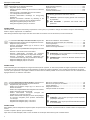 2
2
-
 3
3
-
 4
4
-
 5
5
-
 6
6
-
 7
7
-
 8
8
-
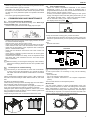 9
9
-
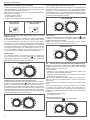 10
10
-
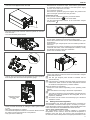 11
11
-
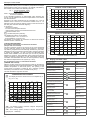 12
12
-
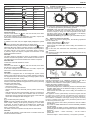 13
13
-
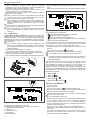 14
14
-
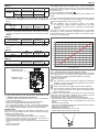 15
15
-
 16
16
-
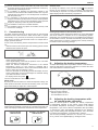 17
17
-
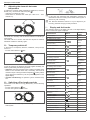 18
18
-
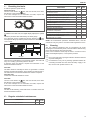 19
19
-
 20
20
-
 21
21
-
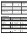 22
22
-
 23
23
-
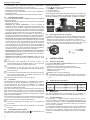 24
24
-
 25
25
-
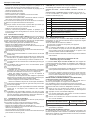 26
26
-
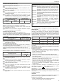 27
27
-
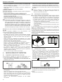 28
28
-
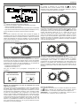 29
29
-
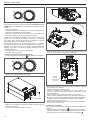 30
30
-
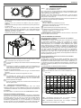 31
31
-
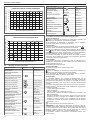 32
32
-
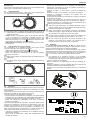 33
33
-
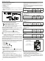 34
34
-
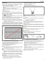 35
35
-
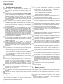 36
36
-
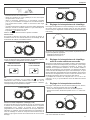 37
37
-
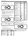 38
38
-
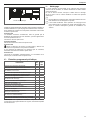 39
39
-
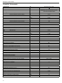 40
40
-
 41
41
-
 42
42
-
 43
43
-
 44
44
-
 45
45
-
 46
46
-
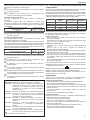 47
47
-
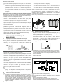 48
48
-
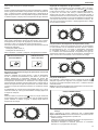 49
49
-
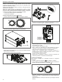 50
50
-
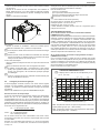 51
51
-
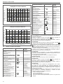 52
52
-
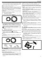 53
53
-
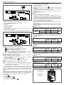 54
54
-
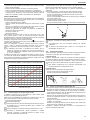 55
55
-
 56
56
-
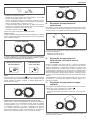 57
57
-
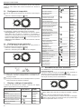 58
58
-
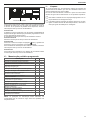 59
59
-
 60
60
-
 61
61
-
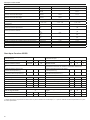 62
62
-
 63
63
-
 64
64
-
 65
65
-
 66
66
-
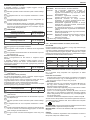 67
67
-
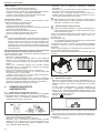 68
68
-
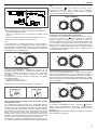 69
69
-
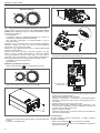 70
70
-
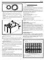 71
71
-
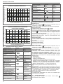 72
72
-
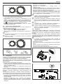 73
73
-
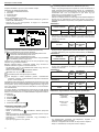 74
74
-
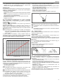 75
75
-
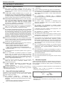 76
76
-
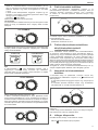 77
77
-
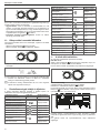 78
78
-
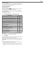 79
79
-
 80
80
-
 81
81
-
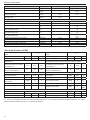 82
82
-
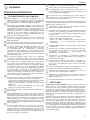 83
83
-
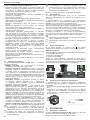 84
84
-
 85
85
-
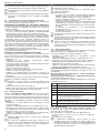 86
86
-
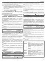 87
87
-
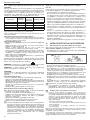 88
88
-
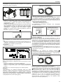 89
89
-
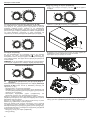 90
90
-
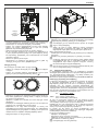 91
91
-
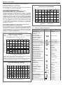 92
92
-
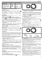 93
93
-
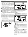 94
94
-
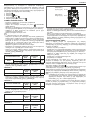 95
95
-
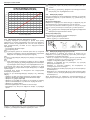 96
96
-
 97
97
-
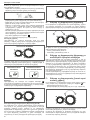 98
98
-
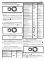 99
99
-
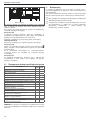 100
100
-
 101
101
-
 102
102
-
 103
103
-
 104
104
-
 105
105
-
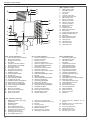 106
106
-
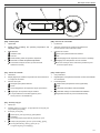 107
107
-
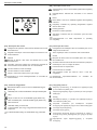 108
108
-
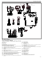 109
109
-
 110
110
-
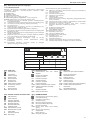 111
111
-
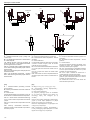 112
112
-
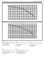 113
113
-
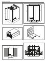 114
114
-
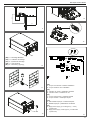 115
115
-
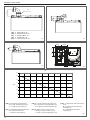 116
116
-
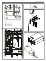 117
117
-
 118
118


