La page est en cours de chargement...

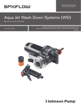
INSTRUCTION MANUAL
ORIGINAL INSTRUCTIONS/TRANSLATION OF ORIGINAL INSTRUCTIONS
READ AND UNDERSTAND THIS MANUAL PRIOR TO OPERATING OR SERVICING THIS PRODUCT
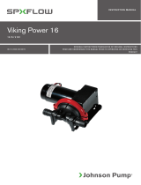
Heavy Duty, Centrifugal Pumps
FLANGED TO 12/24 V DC MOTOR C090P5-1
IB-303 R07 (03/2018)

Index - Indice
Svenska .....................................................................................................................................3
English ....................................................................................................................................... 5
Deutsch .....................................................................................................................................7
Français ..................................................................................................................................... 9
Español ................................................................................................................................... 11
Italiano ................................................................................................................................... 13
Made by SPX FLOW Johnson Pump®
SE: Besök www.spxflow.com för mer information om vår världsomspännande organisation, våra godkännanden,
certifieringar och lokala representanter. SPX FLOW, Inc. förbehåller sig rätten att ändra design och material utan
föregående avisering. Designelement, konstruktionsmaterial och dimensioner som beskrivs i denna bulletin gäller
endast som information och skall alltid bekräftas skriftligt för att vara gällande.
EN: For more information about our worldwide locations, approvals, certifications, and local representatives, please visit
www.spxflow.com. SPX FLOW, Inc. reserves the right to incorporate our latest design and material changes without
notice or obligation. Design features, materials of construction and dimensional data, as described in this bulletin,
are provided for your information only and should not be relied upon unless confirmed in writing.
DE: Für weitere Informationen über unsere weltweiten Standorte, Zulassungen, Zertifizierungen und unsere Vertreter
vor Ort, besuchen Sie bitte unsere Webseite: www.spxflow.com. Die SPX FLOW, Inc. behält sich das Recht vor,
die neuesten Konstruktions- und Werkstoffänderungen ohne vorherige Ankündigung und ohne Verpflichtung hierzu
einfließen zu lassen. Konstruktive Ausgestaltungen, Werkstoffe sowie Maßangaben, wie sie in dieser Mitteilung
beschrieben sind, sind nur zur Information. Alle Angaben sind unverbindlich, es sei denn, sie wurden schriftlich
bestätigt.
FR: Pour plus d’information sur nos succursales internationales, nos approbations, nos certifications et nos
représentants locaux, veuillez consulter notre site Internet au www.spxflow.com. SPX FLOW, Inc. se réserve le droit
d’incorporer nos plus récents concepts ainsi que tout autre modification importante sans préavis ou obligation. Les
éléments décoratifs, matériaux de construction et les données dimensionnelles, tels qu’énoncés dans ce communiqué,
sont fournis pour votre information seulement et ne doivent pas être considérés comme officiels à moins d’avis
contraire par écrit.
ES: Para más información sobre nuestras oficinas a nivel mundial, aprobaciones, certificaciones y representantes
locales, por favor visite www.spxflow.com. SPX FLOW, Inc. se reserva el derecho de incorporar nuestro diseño más
reciente y cambios materiales sin necesidad de notificación previa u obligación de ningún tipo. Características de
diseño, materiales de construcción y dimensiones, tal y como están descritas en este boletín, son proporcionadas sólo
con fines informativos y no deben ser usados como referencia a menos que sean confirmados por escrito.
IT: Per ottenere maggiori informazioni sulle nostre sedi nel mondo, autorizzazioni, certificazioni, e rappresentanti locali,
potete visitare il sito www.spxflow.com. La SPX FLOW, Inc. si riserva il diritto di apportare cambiamenti ai propri design
e materiali senza preavviso o vincolo. Le caratteristiche del design, i materiali di costruzione e i dati dimensionali, così
come descritti nel presente bollettino, sono forniti solo per vostra informazione e non saranno oggetto di obbligazione
salvo autorizzazione confermata per iscritto.

3
Översättning av originalinstruktionerna
> Svenska
Typiska användningsområden
Dessa centrifugalpumpar är idealiska för
installation i husvagnar och bussar etc som
cirkulationspumpar t ex vid kylning av färskvat-
ten och för vatten i värmesystem.
Allround-pumpar som kan användas där själv-
sugningsförmåga ej krävs.
Teknisk beskrivning
Pumphus: PA66
Rotor: PA66
Axel: Syrafast stål
Axeltätning: Mekanisk tätning
Motor: Kullagrad permanent-
magnetmotor 12/24 V
Anslutning: 38 mm (1.1/2") slang
O-ring: EPDM
Radioavstörd: EN55014
Modellspecifikation
Pumptyp Best nr Anslutning
C090P5-1 12 V 10-24190-1 38 mm (1.1/2")
C090P5-1 24 V 10-24190-2 38 mm (1.1/2")
Tryck- och kapacitetsdata (se sid 15)
Baserat på vatten vid 20°C/68°F
Reservdelar (se sid 16-17)
Installationsföreskrifter
Pumparna i C0-serien är normalsugande
centrifugalpumpar och ska monteras med
tillrinning alternativt fyllas upp före start.
Obs! Pumpen får ej köras torr.
Pumpen har medurs rotationsriktning, sett
framifrån mot pumphuset (se rotationspil).
Motorerna är konstruerade för kontinuerlig drift
i vätsketemperaturområdet
-30°C – +100°C (-22°F – +212°F).
Pumparna kan installeras horisontellt eller
vertikalt. Vid vertikal installation ska motorn
vändas uppåt. För att undvika luftblåsor bör
utloppet vid horisontellt montage vändas uppåt
eller så att det befinner sig på övre sidan
av pumpen. Pumparna bör ej användas för
sjövatten eller andra starkt förorenade vatten.
Får ej högtryckstvättas.
Omg.temperatur: -30°C – +70°C.
(-22°F – +158°F)
Max systemtryck: 2 bar
Elektrisk installation
Anslut röd kabel till pluspol (+) och svart kabel
till minuspol (-) eller jord.
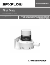
Cirkulationspump C090

4Översättning av originalinstruktionerna
> Svenska
Serviceinstruktioner
Demontering
1. Lossa de fem skruvarna som håller
pumphuset och tag bort detta.
2. Lossa skruven som håller rotorn på
motoraxeln med en 3 mm insexnyckel.
Obs! Vänstergängad. Tag bort rotorn.
3. Tag bort mekaniska tätningens roterande
del från axeln.
4. Tag bort mellandelen och mekaniska
tätningens keramikdel från mellandelen.
Kräng av O-ringen från mellandelen.
5. Lossa de fyra skruvarna som håller flänsen
och tag bort den från motorn.
6. Demontera inte motorn.
Montering
1. Montera flänsen på motorn med de fyra
skruvarna.
2. Tryck in mekaniska tätningens keramikdel
i sitt läge i mellandelen (vinkelrät inom
0,1 mm i förhållande till axeln). Obs!
Tätningsytorna på mekaniska tätningen kan
lätt skadas av smuts, repor fett eller vätska
med partiklar. Behandla tätningens delar
varsamt och rör aldrig vid tätningsytorna
med fingrarna.
3. Montera O-ringen i sitt spår på
mellandelen. Smörj O-ringens utsida med
ett tunt lager fett.
4. Passa in mellandelen i flänsen så att
mellandelens styrklack äntrar i flänsens
urtag.
5. Montera mekaniska tätningens roterande
del på motoraxeln.
6. Skruva fast rotorn på motoraxeln.
Obs! Vänstergängad.
7. Skruva fast pumphuset med de fem
skruvarna.
8. Kontrollera att rotorn roterar fritt i
pumphuset.
Avfallshantering/
materialåtervinning
Vid avfallshantering ska produkten lämnas för
destruktion/återvinning enligt gällande lagstift-
ning. Vid tillämpliga fall demonteras och sorte-
ras produkten i ingående materialfraktioner.

5
Original instructions
> English
Typical applications
These centrifugal pumps are ideal for instal-
lation in recreation vehicles and buses etc for
use as circulating pumps e g when cooling
fresh water and for water in heating systems.
All-round pumps that can be used wherever
self-priming is not essential.
Technical description
Body: PA66
Impeller: PA66
Shaft: Stainless steel
Shaft seal: Mechanical seal
Motor: Permanent magnet motor
12/24 V
Connection: 38 mm (1.1/2") hose
O-ring: EPDM
Radio distur-
bance shielded: EN55014
Type designation
Pumptype Order No Connection
C090P5-1 12 V 10-24190-1 38 mm (1.1/2")
C090P5-1 24 V 10-24190-2 38 mm (1.1/2")
Pressure and capacity data (see p 15)
Based on water at 20°C/68°F
Spare parts (see p 16-17)
Installation recommendations
The C0-series pumps are normal-priming
centrifugal pumps and should be mounted in
a manner that ensures that they are always
flooded or else be primed before being
switched on.
Note! The pump must never be run dry.
The direction of rotation of the pump is clock-
wise, viwed from the front towards the body
(see rotation arrow).
The motors are designed for continuous
operation in liquid temperature range of -30°C
– +100°C (-22°F – +212°F).
The pumps can be installed horizontally or
vertically. When installed vertically the motor
should be above the pump body. To avoid
air-locks when mounted horizontally, the body
should be turned in such a way that the outlet
is directed upwards or is placed on the upper
side of the pump body. The pumps should not
be used for sea-water or other heavy soiled
liquids.
Do not high pressure wash.
Ambient temperature: -30°C – +70°C
(-22°F – +158°F)
Max system pressure: 2 bar.
Electrical installation
Connect red lead to positive (+) terminal and
black lead to negative (-) terminal (or earth).
Circulation pump C090

6Original instructions
> English
Service instructions
Disassembly
1. Loosen the five screws holding the pump
body and remove it.
2. Loosen the screw holding the impeller on
the motor shaft with a
3 mm hexagon wrench. Note! Anti-clock-
wise. Remove the impeller.
3. Remove the rotating part of the mechanical
seal from the shaft.
4. Remove the middle part and the ceramic
part of the mechanical seal from the middle
part. Remove the O-ring from the middle
part.
5. Loosen the four screws holding the flange
and remove the flange from the motor.
6. Do not disassemble the motor.
Assembly
1. Fit the flange to the motor with the four
screws.
2. Push the ceramic part of the mechanical
seal in its position in the middle part (per-
pendicular within
0.1 mm related to the shaft).
Note! The sealing surfaces of the me-
chanical seal may easily be damaged by
dirt, scratching, grease or other solids in
suspension. Therefore be careful with the
sealing parts and never touch the sealing
surfaces with your fingers.
3. Fit the O-ring in the groove of the middle
part. Lubricate the outside of the O-ring
with a thin layer of grease.
4. Fit the middle part in the flange. The middle
part to be turned so that its stud will guide
into the corresponding groove in the
flange.
5. Fit the rotating part of the mechanical seal
onto the motr shaft.
6. Fit the impeller on the motor shaft. Note!
The screw is anti-clockwise.
7. Fit the body with the five screws.
8. Turn the impeller round to check that it is
running free in the body.
Waste handling
material recycling
At the products end of life, please dispose
of the product according to applicable law.
Where applicable, please disassemble the pro-
duct and recycle the parts material.

7
Übersetzung der Original-Betriebanleitungen
> Deutsch
Typische Anwendungen
Diese Kreiselpumpen sind ideal für die Instal-
lation in Wohnmobilen, Caravans etc. als Zir-
kulations-Pumpen für Frisch- wasser oder im
Heizungskreislauf. Diese vielseitigen Pumpen
können überall eingesetzt werden, wo keine
selbstan-saugende Pumpe notwendig ist.
Technische Daten
Gehäuse: PA66
Impeller: PA66
Welle: Edelstahl
Wellendichtung:Gleitring-Dichtung
Motor: Gleichstrom – Permanent
Magnet-Motor 12/24 V
Schlauch-
Anschluß: 38 mm (1.1/2") Schlauch
O-Ring: EPDM
Funkentstörung:EN55014
Typen-Designation
Pumpentype Bestell-Nr. Anschluß
C090P5-1 12 V 10-24190-1 38 mm (1.1/2")
C090P5-1 24 V 10-24190-2 38 mm (1.1/2")
Druck- und Leistungsdagen
(siehe Seite 15)
Basierend auf einer Wassertemperatur von
20°C/68°F
Ersatzteile (siehe Seite 16-17)
Installations-Hinweise
Die CO-Pumpen-Serien sind normale Zentri-
fugal-Pumpen, die so installiert werden sollten,
daß sie stets mit Wasser geflutet sind oder vor
dem Start aufgefüllt werden können.
Vermerk: Die Pumpe darf nicht trockenlaufen!
Die Drehrichtung der Pumpe ist im Uhrzeiger-
sinn, gesehen von der Vorder-seite der Pumpe
zum Pumpenkörper (siehe Drehrichtungs-
Pfeil). Der Motor ist für Dauerlauf im Tempera-
tur-Bereich der Flüssigkeit von
30°C – +100°C (-22°F – +212°F).
Die Pumpe kann horizontal oder vertikal
montiert werden. Bei Vertikal-Installation sollte
der Ansaugstutzen nach unten zeigen (Motor
oben). Bei horizon-taler Installation sollte zur
Vermeidung von Luftblasen der Pumpenauslaß
nach oben zeigen.
Die Pumpe sollte nicht zum Pumpen
von Seewasser oder stark verschmutzten
Flüssigkeiten verwendet werden.
Spülen Sie die Pumpe nicht mit Hoch-druck
aus.
Umgebungs-Temperatur: - 30°C - + 70°C
(-22°F – +158°F)
Max. System-Druck: 2 bar.
Electrische Installation
Verbinden Sie das rote Kabel + mit dem
Pluspol (+) und das schwarze Kabel mit dem
Minuspol (-) der Batterie.
Zentrifugal-Pumpe C090

8Übersetzung der Original-Betriebanleitungen
> Deutsch
Service-Anleitung
Demontage
1. Lösen Sie die fünf Halteschrauben
des Pumpengehäuses und demontieren
Sie dieses.
2. Lösen Sie die Halteschrauben des
Impellers von der Motorwelle mit einem 3
mm Inbusschlüssel.
Achtung! Linksgewinde. Entfernen Sie den
Impeller.
3. Entfernen Sie den rotierenden Teil der
Gleitring-Dichtung von der Welle.
4. Demontieren Sie den mittleren Teil und die
Ceramik-Platte der Gleitring-Dichtung aus
dem mittleren Pumpen-teil. Entfernen Sie
auch den O-Ring.
5. Entfernen Sie die vier Schrauben, die den
Flansch am Motor halten.
6. Demontieren Sie nicht den Motor.
Montage
1. Befestigen Sie den Flansch am Motor mit
den vier Schrauben.
2. Schieben Sie den Ceramic-Teil der
Gleitring-Dichtung in die Position im
Mittelteil der Pumpe (senkrecht zur
Wellenachsel).
Wichtig! Die Oberfläche der
Gleitring-Dichtung kann leicht durch
Schmutz, Kratzer, Fett oder andere Stoffe
beschädigt werden. Deshalb sollten diese
Teile der Wellenabdich-tung vorsichtig
behandelt und nicht mit den Fingern
berührt werden.
3. Der O-Ring wird in die Nute des Mittelteils
eingesetzt. Die Außenseite des O-Rings
sollte leicht eingefettet werden.
4. Jetzt wird das mittelteil der Pumpe
montiert. Dieses Teil muß so gedreht
werdenm daß die Führung in die ent-
sprechende Nute des Flansches faßt.
5. Schieben Sie jetzt den mitlaufenden
Teil der Gleitring-Dichtung auf die
Pumpenwelle.
6. Montieren Sie den Impeller auf der Welle
und schrauben ihn fest. Achtung! Die
Schraube hat Linksgewinde!
7. Befestigen Sie den Pumpenkörper mit den
fünf Schrauben.
8. Drehen Sie den Impeller, um zu prüfen, daß
dieser sich frei bewegen läßt.
Entsorgung/Recycling
Nach Lebensdauerende entsorgen Sie die
Pumpe nach den örtlichen Vorschriften.
Nach Möglichkeit demontieren Sie Teile
der Pumpe um sie dem Recycling-Process
zuzuführen.

9
Traduction du manuel d'instruction d'origine
> Français
Types a l’applications
Ces pompes sont idéales, pour installation
dans les véhicules de loisir, bateaux et
autocars, comme pompes de circulation pour
eau réfrigérée ou circulateur de systèmes de
chauffage.
Ces pompes ne sont pas auto amorçantes.
Caractéristiques techniques
Corps: PA66
Rotor: PA66
Arbre: Acier inoxydable
Etanchéite arbre: Garniture mécanique
Moteur: Aimant permanent
12/24 V
Raccords: 1.1/2" BSP
Bague d’etanchéité: EPDM
Antiparasite radio: EN55014
Spécifications du modèle
Modèle Référence Raccords
C090P5-1 12 V 10-24190-1 38 mm (1.1/2")
C090P5-1 24 V 10-24190-2 38 mm (1.1/2")
Caractéristiques de pression et
capacité (voir page 15)
Basé sur une eau à 20°C.
Pièces de rechange (voir page 16-17)
Recommandations pour
l’installation
Ces pompes de la série CO, non-auto
amorçantes doivent être installées en dessous
du niveau du liquide à pompes, sinon elles
doivent être amorcées lors de chaque mise en
route.
Note : ces pompes ne doivent pas tourner à
sec.
Le sens de rotation est le sens horloge (vue :
face à la pompe).
Les moteurs sont prévus pour une utilisation
permanente dans les gammes de températures
de liquide de -30 à +100°C.
Les pompes peuvent être installées
horizontalement ou verticalement, dans ce
dernier cas, le moteur doit être plus haut que
le corps de pompe.
Pour faciliter l’amorçage, lorsque la pompe est
installée horizontalement, orienter le corps de
pompe de manière à ce que la sortie soit sur
le dessus.
Ne pas utiliser la pompe pour l’eau de mer ou
pour liquides lourdement chargés.
Ne pas laver à haute pression.
Température ambiante : -30 à +70° C
Pression maximum : 2 bars
Installation électrique
Brancher le câble rouge à la borne positive (+)
et le câble noir à la borne négative (-).
Pompe de circulation C090

10 Traduction du manuel d'instruction d'origine
> Français
Service instructions
Démontage
1. Dévisser les cinq vis fixant le corps de
pompe et déposer celui-ci.
2. Dévisser la vis fixant le rotor sur
l’arbre (clé hexagonale 3 mm)
(dévisser dans le sens d’une horloge).
Déposer le rotor.
3. Déposer la partie tournante du joint
d’étanchéité.
4. Retirer la partie centrale de la
pompe, avec la céramique et déposer
le joint torique.
5. Dévisser les quatre vis fixant la bride
sur le moteur et déposer cette bride.
6. Ne pas démonter le moteur.
Remontage
1. Fixer la bride sur le moteur par ses
quatre vis
2. Pousser la céramique du joint
tournant dans sa cavité sur la partie
centrale de la pompe (tolérance de
perpendicularité 0,1 mm par rapport
à l’arbre)
Les surfaces de frottement de la
garniture mécanique ne doivent pas
être détériorées et être exemptes de
poussières, graisse ou autre produit.
Eviter de les toucher avec les doigts
3. Mettre le joint torique en place dans
sa gorge et lubrifier légèrement
l’extérieur à la graisse.
4. Mettre en place la partie centrale de
la pompe dans la bride, vérifier son
orientation par rapport à la gorge.
5. Enfiler la partie tournante du joint
sur l’arbre.
6. Mettre en place le rotor et le visser
( visser dans le sens inverse de
l’horloge)
7. Mettre en place le corps de la pompe
et le fixer par ses cinq vis
8. Tourner le rotor pour vérifier qu’il ne
frotte pas sur le corps de pompe.
Gestion des déchets/recyclage des
matériaux
Lorsque le matériel arrivera en fin de vie,
veuillez le mettre au rebut en fonction des lois
applicables. Lorsque c'est possible, veuillez
démonter le matériel et recycler les pièces
pouvant l'être

11
Traducción de instrucciones originales
> Español
Aplicaciones
Esta bomba centrífuga es ideal para instalacio-
nes en yates, autocares, etc., como bomba de
trasvase en equipos de refrigeración y calefac-
ción. Y para cualquier trabajo de bombeo
donde no se precise autocebado.
Descripción técnica
Cuerpo: PA66
Impulsor: PA66
Eje: Acero inoxidable
Retén eje: Retén mecánico
Motor: De imán permanente,
12/24 V
Conexiones: Tubo 38 mm (1,1/2")
Aro tórico: EPDM
Protección anti-
parásitos radio: EN55014
Modelos
Bomba Referencia Conexión
C090P5-1 12 V 10-24190-1 38 mm (1.1/2")
C090P5-1 24 V 10-24190-2 38 mm (1.1/2")
Caudales y presiones (Ver pag. 15)
Con agua a 20°C/68°F
Recambios (Ver pag. 16-17)
Normas de instalación
Las bombas serie C0, tienen la capacidad
normal de succión de las bombas centrífugas
y deben montarse de forma que siempre estén
cebadas antes de ponerlas en marcha.
Nota: Nunca deben funcionar en seco.
El giro de la bomba es dextrorso, mirándolo de
frente (ver la flecha). El motor puede funcionar
continuamente a la temperatura de líquido de
-30°C – +100°C (-22°F – +212°F). La bomba
puede instalarse en posición vertical u horizon-
tal. Cuando se instale en posición vertical, el
motor deberá colocarse encima del cuerpo de
la bomba. Para evitar fugas de aire cuando se
instala en posición horizontal, girar el cuerpo
de modo que el racor de salida quede hacia
arriba o quede situado en la parte más alta del
cuerpo de la bomba. La bomba no debe utili-
zarse para agua salada o líquidos muy sucios.
Temperatura ambiente: -30°C – +70°C
(-22°F – +158°F)
Presión máxima: 2 bar.
Instalación eléctrica
Conectar el cable rojo al positivo (+) y el
negro al negativo (-) (o a tierra).
Bomba trasvase C090

12 Traducción de instrucciones originales
> Español
Instrucciones mantenimiento
Desmontaje
1. Desatornillar los cinco tornillos que sujetan
el cuerpo de la bomba y sacarla.
2. Quitar el tornillo del eje del motor con una
llave de 3 mm. Nota! Giro a la izquierda.
Sacar el impulsor.
3. Quitar del eje la parte giratoria del retén
mecánico.
4. Sacar la parte intermedia y la cerámica,
del retén mecánico; Quitar el aro tórico de
la parte intermedia. Destornillar los cuatro
tornillos que sujetan la brida y sacarla del
motor.
5. No desmontar el motor.
Montaje
1. Fijar la brida al motor con los cuatro tornil-
los.
2. Colocar la pieza de cerámica del retén
mecánico en su lugar (perpendicular
alrededor de 0,1 mm. referente al eje).
Nota: Las superficies de estanqueidad de
retén mecánico pueden estropearse con
facilidad, por el polvo, rascadas, grasa u
otros sólidos en suspensión. Por ello tener
cuidado de no tocar con los dedos las
superficies de estanqueidad.
3. Colocar el aro tórico en la ranura del cen-
tro. Engrasar el áro tórico con una capa
fina de grasa.
4. Colocar la parte intermedia en la brida,
girándola hasta que el saliente encaje en la
ranura de la brida.
5. Instalar la parte giratoria del retén mecáni-
co en el eje del motor.
6. Colocar el impulsor en el eje.
7. Poner el cuerpo con los cinco tornillos.
8. Hacer girar el impulsor para comprobar
que gira libremente.
Desguace/Reciclado
Al final de la vida del equipo disponga de este
de acuerdo a la ley. Donde sea de aplicación
desmonte el equipo y recicle los diferentes
materiales.

13
Traduzione delle istruzioni originali
> Italiano
Applicazioni tipiche
Queste pompe di circolazione sono indicate
per l’installazione su veicoli da diporto, autobus
ecc. e per essere utilizzate come pompe di
circolazione, ad es. negli impianti di raffred-
damento per acqua potabile e di distribuzione
acqua negli impianti di riscaldamento. Grazie
alla loro versatilità, queste pompe possono es-
sere utilizzate ogni volta che il sistema
autoadescante non è essenziale.
Descrizione tecnica
Corpo: PA66
Girante: PA66
Albero: acciaio inossidabile
Guarnizione
albero: guarnizione meccanica
Motore: motore a magnete
permanente 12/24 V
Collegamento: tubo da 38 mm (1.1/2")
Anello di tenuta
toroidale: gomma EPDM
Schermatura
disturbi radio: EN55014
Destinazione tipo
Tipo di pompa N° ordine Collegamento
C090P5-1 12 V 10-24190-1 38 mm (1.1/2")
C090P5-1 24 V 10-24190-2 38 mm (1.1/2")
Dati relativi alla pressione e alla
portata (vedere pag. 15)
Con acqua a 20°C/68°F
Parti di ricambio (vedere pagg. 16-17)
Istruzioni di installazione
Le pompe della serie C0 sono pompe cen-
trifughe ad adescamento normale e devono
essere installate in maniera tale da garantire
la continua presenza di fluido o l’adescamento
prima dell’avvio.
Nota! Non utilizzare mai la pompa a secco. Il
motore della pompa ruota in senso orario, se si
osserva la pompa dal lato anteriore in dire-
zione del corpo (vedere la freccia che indica la
direzione di rotazione). I motori sono progettati
per un esercizio continuativo a temperature
di liquido comprese tra -30°C e +100°C (tra
-22°F e +212°F).
Le pompe possono essere installate sia in oriz-
zontale che in verticale. Nella configurazione
d’installazione in verticale, il motore deve sem-
pre trovarsi al di sopra del corpo della pompa.
Per evitare la formazione di sacche d’aria nella
configurazione in orizzontale, il corpo deve
essere girato in maniera tale che l’uscita sia di-
retta verso l’alto oppure sia posizionata sul lato
superiore del corpo della pompa. Le pompe
non sono indicate per l’uso di acqua marina o
di altri liquidi fortemente inquinati.
Non lavare la pompa con getti ad alta pres-
sione.
Temperatura
ambiente: compresa tra -30°C e +70°C
(tra -22°F e +158°F)
Pressione massima
del sistema: 2 bar.
Collegamenti elettrici
Collegare il conduttore rosso al polo positivo
(+) ed il conduttore nero al polo negativo (-)
(o a terra).
Pompa di circolazione C090

14 Traduzione delle istruzioni originali
> Italiano
Istruzioni di manutenzione
Smontaggio
1. Rimuovere le cinque viti che bloccano
in posizione il corpo della pompa per
poi estrarlo.
2. Rimuovere con una chiave esagonale
da 3 mm la vite che blocca in posizione
la girante sull’albero del motore.
Nota! In senso antiorario. Rimuovere
la girante.
3. Rimuovere dall’albero la parte rotante
della guarnizione meccanica.
4. Rimuovere la parte centrale e la parte
ceramica della guarnizione meccanica
dalla sezione centrale. Rimuovere
l’anello di tenuta toroidale dalla
sezione centrale.
5. Rimuovere le quattro viti che bloccano
in posizione la flangia e rimuovere
quest’ultima dal motore.
6. Non smontare il motore.
Montaggio
1. Bloccare la flangia sul motore a mezzo
delle quattro viti.
2. Spingere la parte ceramica della
guarnizione meccanica in posizione
centrale (perpendicolarmente, entro
0.1 mm rispetto all’albero).
Nota! Le superfici sigillanti della
guarnizione meccanica possono essere
facilmente danneggiate da sporcizia,
abrasioni, grasso o altre particelle
sospese. Occorre pertanto maneggiare
con cautela le parti sigillanti ed evitare
di toccarle con le dita.
3. Inserire l’anello di tenuta toroidale
nella scanalatura della sezione
centrale. Lubrificare la parte esterna
dell’anello di tenuta toroidale con un
sottile strato di grasso.
4. Inserire la parte centrale nella flangia
e girarla in modo che il perno scorra
all’interno della corrispondente
scanalatura della flangia.
5. Montare la parte rotante nella
guarnizione meccanica sopra l’albero
motore.
6. Montare la girante sull’albero motore.
Nota! La vite va fissata in senso
antiorario.
7. Bloccare il corpo in posizione tramite
le cinque viti.
8. Ruotare la girante per accertarsi che
giri liberamente all’interno del corpo.
Gestione dei rifiuti/
riciclaggio dei materiali
Al termine della vita del prodotto si prega di
smaltire il prodotto secondo le leggi in vigore
per queste operazioni. Quando possibile, si
raccomanda di smontare il prodotto e riciclare i
materiali dei componenti.

15
SVENSKA
ENGLISH
DEUTSCH
FRANÇAIS
ESPAÑOL
ITALIANO
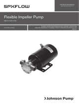
Tryck- och kapacitet Tryck Flöde Strömförbr.
Bar kPa ft l/min USGPM 12 V 24 V
Slanganslutning
ø 38 mm (1,1/2")
0,10 10 3,4 100,0 26,4 7, 4 4,4
0,25 25 8,4 67, 0 1 7,7 7, 2 4,0
0,40 40 13,4 32,0 8,5 6,6 3,5
Rek. säkring 10,0 6,0
Pressure and capacity Pressure Flow Amperage
Bar kPa ft l/min USGPM 12 V 24 V
Hose connection
ø 38 mm (1,1/2")
0,10 10 3,4 100,0 26,4 7, 4 4,4
0,25 25 8,4 67, 0 1 7,7 7, 2 4,0
0,40 40 13,4 32,0 8,5 6,6 3,5
Fuse required 10,0 6,0
Druck- und Leistung Druck Fördermenge Stromverbrauch
Bar kPa ft l/min USGPM 12 V 24 V
Schlauchanschluß
ø 38 mm (1,1/2")
0,10 10 3,4 100,0 26,4 7, 4 4,4
0,25 25 8,4 67, 0 1 7,7 7, 2 4,0
0,40 40 13,4 32,0 8,5 6,6 3,5
Empfohlene Sicherung 10,0 6,0
Pression et débit Pression Débit Intensité
Bar kPa ft l/min USGPM 12 V 24 V
Raccord de flexible
ø 38 mm (1,1/2")
0,10 10 3,4 100,0 26,4 7, 4 4,4
0,25 25 8,4 67, 0 1 7,7 7, 2 4,0
0,40 40 13,4 32,0 8,5 6,6 3,5
Fusible nécessaire 10,0 6,0
Presiones y caudales Presión Caudal Amperaje
Bar kPa ft l/min USGPM 12 V 24 V
Conexión tubo
ø 38 mm (1,1/2")
0,10 10 3,4 100,0 26,4 7, 4 4,4
0,25 25 8,4 67, 0 1 7,7 7, 2 4,0
0,40 40 13,4 32,0 8,5 6,6 3,5
Fusible recomendado 10,0 6,0
Pressione e portata Pressione Portata Amperaggio
Bar kPa ft l/min USGPM 12 V 24 V
Sezione tubo
ø 38 mm (1,1/2")
0,10 10 3,4 100,0 26,4 7, 4 4,4
0,25 25 8,4 67, 0 1 7,7 7, 2 4,0
0,40 40 13,4 32,0 8,5 6,6 3,5
Fusibile raccomandato 10,0 6,0

16

17
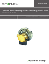
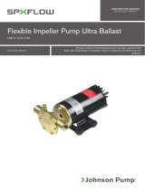
Pos Nos Benämning Description Bezeichnung Art.-Nr.
1* 1 Pumphus Body Gehäuse 01-24191
2 1 Mellandel Middle part Mittelteil 01-24192
3 1 Fläns Flange Flansch 01-24193
4 1 Pumphjul Impeller Laufrad 01-35162
5 4 Bricka Washer Scheibe 0.0350.115
6 1 Skruv Screw Schraube 01-45749
7 1 Bricka Washer Scheibe 01-45601
8 4 Bricka Washer Scheibe 0.0352.104
9 1 Motor 12 V Motor 12 V Motor 12 V 01-24537-01
1 Motor 24 V Motor 24V Motor 24V 01-24537-02
1 Motor 32 V Motor 32 V Motor 32 V 01-24537-03
10 1 Mek. tätning Mech. seal Gleitringdichtung 09-0.2247.023
11* 1 O-ring O-ring O-Ring 0.2173.457
12* 5 Skruv Screw Schraube 0.0319.500
13 4 Skruv Screw Schraube 0.0278.037
* 1 Servicekit Service kit Servicesatz 09-46283
Pos Nos Description Descripción Descrizione Art No
1* 1 Corps de pompe Cuerpo Alloggiamento 01-24191
2 1 Middle part Middle part Middle part 01-24192
3 1 Flange Flange Flange 01-24193
4 1 Turbine Impulsor Girante 01-35162
5 4 Rondelle Arandela Rondella 0.0350.115
6 1 Vis Tornillos Viti 01-45749
7 1 Rondelle Arandela Rondella 01-45601
8 4 Rondelle Arandela Rondella 0.0352.104
9 1 Moteur 12 V Motor 12 V Motore 12 V 01-24537-01
1 Moteur 24 V Motor 24V Motore 24V 01-24537-02
1 Moteur 32 V Motor 32 V Motore 32 V 01-24537-03
10 1 Garniture mech Retén mecánico Guarnizione mecc 09-0.2247.023
11* 1 Joint torique Aro tórico O-ring 0.2173.457
12* 5 Vis Tornillos Viti 0.0319.500
13 4 Vis Tornillos Viti 0.0278.037
* 1 Kit de réparation Juego recambios Kit de servizio 09-46283
Reservdelslista
Parts list
Ersatzteilliste
Liste des pièces
Lista de piezas
Elenco delle parti


Heavy Duty,
Centrifugal Pumps
FLANGED TO 12/24 V DC MOTOR
C090P5-1
IB-303 R07 ISSUED 03/2018 COPYRIGHT © 2018 SPX FLOW INC.
Customer Service & Support - Johnson Pump Marine
SE +46 19 21 83 10
johnson-pump.marine@spxflow.com
US +1 847 671-7867
jp-customerservice@spxflow.com
AUS +61 03 9589 9222
ft.aus.cs@spxflow.com
For more information about our worldwide locations, approvals, certifications,
and local representatives, visit Johnson Pump - Marine at www.spxflow.com
SPX FLOW, Inc. reserves the right to incorporate our latest design and material changes without notice or obligation.
Design features, materials of construction and dimensional data, as described in this bulletin, are provided for your
information only and should not be relied upon unless confirmed in writing. Please contact your local sales representative
for product availability in your region. For more information visit www.spxflow.com.
The green “
”
and “
” are trademarks of SPX FLOW, Inc.
/