SPX FLOW Heavy Duty Electro-Magnetic Clutch Pump FB-5001 Series Manuel utilisateur
- Taper
- Manuel utilisateur

INSTRUCTION MANUAL
ORIGINAL INSTRUCTIONS/TRANSLATION OF ORIGINAL INSTRUCTIONS
READ AND UNDERSTAND THIS MANUAL PRIOR TO OPERATING OR SERVICING THIS
PRODUCT
Flexible Impeller Pump with Electromagnetic Clutch
F7B-5001/-50017, F8B-5001/-5017
IB-504 R06 (03/2018)

INDEX INDICE
Svenska ............................................................................................................ 3
English .............................................................................................................. 5
Deutsch ............................................................................................................. 7
Français ............................................................................................................. 9
España ............................................................................................................. 11
Italiano .............................................................................................................13
Pressure and capacity data ........................................................................15
Parts list...........................................................................................................16
Weights and dimensions .............................................................................17
Accessories .................................................................................................... 20
Made by SPX FLOW Johnson Pump®
SE: Besök www.spxflow.com för mer information om vår världsomspännande organisation, våra godkännanden,
certifieringar och lokala representanter. SPX FLOW, Inc. förbehåller sig rätten att ändra design och material utan
föregående avisering. Designelement, konstruktionsmaterial och dimensioner som beskrivs i denna bulletin gäller
endast som information och skall alltid bekräftas skriftligt för att vara gällande.
EN: For more information about our worldwide locations, approvals, certifications, and local representatives, please visit
www.spxflow.com. SPX FLOW, Inc. reserves the right to incorporate our latest design and material changes without
notice or obligation. Design features, materials of construction and dimensional data, as described in this bulletin,
are provided for your information only and should not be relied upon unless confirmed in writing.
DE: Für weitere Informationen über unsere weltweiten Standorte, Zulassungen, Zertifizierungen und unsere Vertreter
vor Ort, besuchen Sie bitte unsere Webseite: www.spxflow.com. Die SPX FLOW, Inc. behält sich das Recht vor,
die neuesten Konstruktions- und Werkstoffänderungen ohne vorherige Ankündigung und ohne Verpflichtung hierzu
einfließen zu lassen. Konstruktive Ausgestaltungen, Werkstoffe sowie Maßangaben, wie sie in dieser Mitteilung
beschrieben sind, sind nur zur Information. Alle Angaben sind unverbindlich, es sei denn, sie wurden schriftlich
bestätigt.
FR: Pour plus d’information sur nos succursales internationales, nos approbations, nos certifications et nos
représentants locaux, veuillez consulter notre site Internet au www.spxflow.com. SPX FLOW, Inc. se réserve le droit
d’incorporer nos plus récents concepts ainsi que tout autre modification importante sans préavis ou obligation. Les
éléments décoratifs, matériaux de construction et les données dimensionnelles, tels qu’énoncés dans ce communiqué,
sont fournis pour votre information seulement et ne doivent pas être considérés comme officiels à moins d’avis
contraire par écrit.
ES: Para más información sobre nuestras oficinas a nivel mundial, aprobaciones, certificaciones y representantes
locales, por favor visite www.spxflow.com. SPX FLOW, Inc. se reserva el derecho de incorporar nuestro diseño más
reciente y cambios materiales sin necesidad de notificación previa u obligación de ningún tipo. Características de
diseño, materiales de construcción y dimensiones, tal y como están descritas en este boletín, son proporcionadas sólo
con fines informativos y no deben ser usados como referencia a menos que sean confirmados por escrito.
IT: Per ottenere maggiori informazioni sulle nostre sedi nel mondo, autorizzazioni, certificazioni, e rappresentanti locali,
potete visitare il sito www.spxflow.com. La SPX FLOW, Inc. si riserva il diritto di apportare cambiamenti ai propri design
e materiali senza preavviso o vincolo. Le caratteristiche del design, i materiali di costruzione e i dati dimensionali, così
come descritti nel presente bollettino, sono forniti solo per vostra informazione e non saranno oggetto di obbligazione
salvo autorizzazione confermata per iscritto.

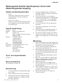
Översättning av originalinstruktionerna
> Svenska
Självsugande flexibel impellerpump i brons med
elektromagnetisk koppling
Typiska användningsområden
• Marint
Länspump, spolpump för däck och utrust-
ning, kylpump för motorer, brandpump,
sköljning av fisk.
• Industri och jordbruk
Pumpen kan monteras på kraftuttag på trak-
torer, vägmaskiner och liknande för bevatt-
ning, spolning etc.
Teknisk beskrivning
Pumphus: Brons
Impeller: Neopren, EPDM alt nitril
Axel: Syrafast stål
Axeln är lagrad i permanentsmorda
dubbla kullager
Tätning: F7B-5001/-50017
- läpptätning alt.
mekanisk tätning
F8B-5001/-50017
- mekanisk tätning
Kam: Hel alt reducerad
Anslutning: Se ”Modellspecifikation”, sid 4
Koppling: Elektromagnetisk,
2xA-spår alt 1xB-spår,
Spänning:
12 V (4 A) DC
24 V (2 A) DC
Tryck- och kapacitetsdata
Se sid 15.
Serviceinstruktion
Se reservdelslista sid 16-19.
Demontering
1. Lossa pumplocket och tag bort packningen
alt. O-ringen.
2. Tag ur impellern med t ex två skruvmejslar.
3. Demontera kammen och tag bort tätnings-
medlet på kammen och i pumphuset. Tag
även bort slitbrickan.
4. Demontera läpptätningen alt mekaniska
tätningen. Tag bort O-ringen (ej möjligt från
detta håll för F7B).
5. Lossa skruven (pos 21) och avlägsna
kopplingen från pumpaxeln. Om nödvändigt
skruva i en UNC 5/8”- skruv i kopplingens
centrumhål för att pressa bort kopplingen
från pumpaxeln.
6. Lossa skruvarna (pos 24) och demontera
fältspolen.
7. Demontera låsringen (pos 12) som håller
lagerpaketet.
8. Demontera axeln med kullagren genom att
pressa på axeländen från impellersidan.
9. Demontera kullagren/låsringen och distans-
hylsan samt O-ringen för F7B (pos 27). På
F8B får inte kullagren pressas över tätnings-
ytan.
Montering
1. Montera kullager/låsring och distanshylsa på
axeln samt O-ringen för F7B. På F8B får inte
kullagren pressas över tätningsytan.
2. Pressa i axeln med kullagren i pumphuset
och montera låsringen (pos 12).
3. Montera fältspolen med skruvarna (pos 24)
och lås dem med åtdragningsmoment 7±1
Nm. På F7B montera även bricka (pos 29)
på pumphuset.
4. Montera kopplingen på pumpaxeln med kil
(pos 15).
5. Montera O-ringen (F8B) och läpptätningen
(fjädern i läpptätningen ska vara vänd mot
impellern) alt mekaniska tätningen.
6. Montera slitbrickan.
7. Skruva fast kammen, men lägg först på
tätningsmedel på kam och kamskruv för att
förhindra läckage.
8. Smörj impellern med Johnson impeller lubri-
cant och montera med en roterande rörelse i
impellerns rotationsriktning.
9. Montera packningen alt. O-ringen och
skruva fast locket.
3

Översättning av originalinstruktionerna
> Svenska
Modellspecifikation
Pump med neoprenimpeller och helkam
Pumptyp Art nr Anslutning Tätning
F7B-5001 10-24577-13 BSP 1” Läpptätning
F7B-50017 10-24577-19 NPTF 1”-111/2 Läpptätning
F7B-5001 10-24577-99 BSP 1” Mekanisk tätning
F7B-50017 10-24577-98 NPTF 1”-111/2 Mekanisk tätning
F8B-5001 10-13022-99 BSP 11/2” Mekanisk tätning
F8B-50017 10-13022-98 NPTF 11/2”-111/2 Mekanisk tätning
F8B-50017 10-13022-96 NPTF 11/2”-111/2 Mekanisk tätning
F8B-50017 10-13022-95 NPTF 11/4”-111/2 Mekanisk tätning
Ovanstående artikelnummer anger pump exklusive elektromagnetisk koppling.
Övriga varianter på förfrågan.
Elektromagnetisk koppling
Spänning Art nr Spår
12 V 0.3454.001 2xA
24 V 0.3454.002 2xA
12 V 0.3454.003 1xB
24 V 0.3454.004 1xB
Tillbehör
Se sid 20-21.
Avfallshantering/materialåtervinning
Vid avfallshantering ska produkten lämnas för destruktion/återvinning enligt gällande lagstiftning. Vid till-
lämpliga fall demonteras och sorteras produkten i ingående materialfraktioner.
4

Original instructions
> English
Self-priming, flexible impeller pump of bronze with
electro-magnetic clutch
Typical applications
• Marine
Bilge pump, wash-down for decks and
equipment, emergency engine cooling
pump, emergency fire pump, fish washing.
• Industry and agriculture
The pump can be mounted on the power
take-off of a tractor, road grader etc for ir-
rigation, washing etc.
Design features
Body: Bronze
Impeller: Neoprene, EPDM or nitrile
Shaft: Stainless steel
The shaft is mounted
with permanently lubricated
double ball bearings
Seal: F7B-5001/-50017 - lip seal
alt. mechanical seal
F8B-5001/-50017
- mechanichal seal
Cam: Full or reduced
Connection: See ”Type designation”, page 6
Clutch: Electro-magnetic,
2xA-groove or 1xB-groove
Supply voltage:
12 V (4 amps) DC
24 V (2 amps) DC
Pressure and capacity data
See page 15.
Service instructions
See parts list pages 16-19.
Disassembly
1. Remove endcover and gasket alt. the oring.
2. Pull out the impeller using two screw drivers
or other suitable implement.
3. Remove the cam and wash away residual
traces of sealing compound on the cam and
inside the pump body. Remove the wear
plate.
4. Remove lip seal alt mech seal. Remove the
o-ring (not possible from this direction on
F7B)
5. Back off the screw (pos 21) and remove the
clutch from the shaft. If necessary, screw a
UNC 5/8” screw into the centre hole of the
clutch in order to press the clutch off the
shaft.
6. Back off the screws (pos 24) and remove
the field coil.
7. Remove the retaining ring (pos 12) for the
bearing assembly.
8. Remove the shaft with ball bearings by
pressing on the shaft end from the impeller
side.
9. Remove the ball bearings/retaining ring and
the spacer and on F7B also the O-ring (pos
27). On F8B do not press the ball bearings
over the sealing surface.
Assembly
1. Mount ball bearings/retaining ring and the
spacer on the shaft and on F7B also the O-
ring. On F8B do not press the ball bearings
over the sealing surface.
2. Press the shaft with ball bearings into the
body and fit the retaining ring (pos 12).
3. Mount the field coil using the screws (pos
24) and tighten with torque of 7±1 Nm. On
F7B also mount the washer (pos 29) on the
body.
4. Mount the clutch on the pump shaft with a
key (pos 15).
5. Mount o-ring (F8B) and lip seal (spring
towards the impeller) alt mechanical seal.
6. Mount the wear plate.
7. Fasten the cam, but before doing so apply
sealing compound to cam and screw in
order to prevent leakage.
8. Lubricate the impeller with JP Impeller lub-
ricant and fit it with a rotating movement in
the intended direction of impeller rotation.
9. Fit the gasket alt. the O-ring before moun-
ting the endcover.
5

Original instructions
> English
Type designation
Pump with impeller neoprene and full cam
Pump type Part No Connection Seal
F7B-5001 10-24577-13 BSP 1” Lipseal
F7B-50017 10-24577-19 NPTF 1”-111/2 Lipseal
F7B-5001 10-24577-99 BSP 1” Mechanical seal
F7B-50017 10-24577-98 NPTF 1”-111/2 Mechanical seal
F8B-5001 10-13022-99 BSP 11/2” Mechanical seal
F8B-50017 10-13022-98 NPTF 11/2”-111/2 Mechanical seal
F8B-50017 10-13022-96 NPTF 11/2”-111/2 Mechanical seal
F8B-50017 10-13022-95 NPTF 11/4”-111/2 Mechanical seal
The Part Nos above do not include electromagnetic clutch.
Other variants on request.
Electromagnetic clutch
Voltage Part No Pulley
12 V 0.3454.001 2xA
24 V 0.3454.002 2xA
12 V 0.3454.003 1xB
24 V 0.3454.004 1xB
Accessories
See page 20-21.
Waste handling/material recycling
At the products end of life, please dispose of the product according to applicable law. Where applica-
ble, please disassemble the product and recycle the parts material.
6

Übersetzung der Original-Betriebanleitungen
> Deutsch
Selbstansaugende flexible Impellerpumpe aus Bronze
auf Sockel montiert
Anwendungsbeispiele
• Marinebereich
Lenzpumpe, Deckwaschpumpe, Kühlwas-
serpumpe für Motoren, Feuerlöschpumpe,
zum Abspülen von Ausrüstungen und eing-
ebrachter Fänge auf Fischereifahrzeugen.
• Industrie und Landwirtschaft
Die Pumpe kann an die Kraftabnahmen der
Motoren von LKW’s, Traktoren, Strassen-
baumaschinen etc. zum Bewässern, Spülen
angebracht werden.
Technische Beschreibung
Pumpen-
gehäuse: Bronze
Impeller: Neoprene, EPDM oder Nitrile
Welle: Edelstahl mit zwei
dauergeschmierten
Kugellagern
Dichtung: F7B-5001/-50017 – Lippendichtung
bzw. Wellenabdichtung
F8B-5001/-50017 -
Wellenabdichtung
Kamm: 1/1 oder reduzierter Kamm
Anschlüsse: Siehe ”Ausführungen”,
Seite 8
Kupplung: Elektromagnetisch,
2xA-Profil oder 1xB-Profil
Spannung:
12 V (4 A)
24 V (2 A)
Druck und Leistungsdaten
Siehe Seite 15.
Bedienungsanleitung
Siehe Ersatzteilliste Seite 16-19.
Demontage
1. Endabdeckung und Dichtung bzw. O-Ring
abnehmen
2. Den Impeller mit Hilfe von zwei Schrauben-
ziehern oder dem Inpellerabzieher heraus-
ziehen.
3. Welle abnehmen und Dichtmittelreste von
der Welle und im Pumpengehäuse abwa-
schen. Verschleißplatte abnehmen.
4. Lippen- bzw. Wellenabdichtung abnehmen.
O-Ring abnehmen (bei F7B aus dieser
Richtung nicht möglich).
5. Schraube (Pos 21) abnehmen und die
Kupplung von der Pumpenwelle entfernen.
Wenn nötig, eine UNC 5/8” Schraube in
die Zentrumsbohrung einschrauben und die
Kupplung von der Welle drücken.
6. Schrauben (Pos. 24) lösen und Feldspule
abnehmen
7. Sicherungsring (Pos 12) für die Kugellager
abnehmen.
8. Welle und Kugellager durch Druck auf die
Welle von der Impellerseite herausdrücken.
9. Kugellager/Sicherungsring und Distanzring
abnehmen, bei F7B auch den O-Ring (Pos.
27). Bei F8B die Kugellager nicht über die
Dichtfläche drücken.
Montage
1. Kugellager/Sicherungsring und Distanzring
auf die Welle montieren, bei F7B auch den
O-Ring (Pos. 27). Bei F8B die Kugellager
nicht über die Dichtfläche drücken.
2. Welle mit Kugellager in das Pumpengehäuse
pressen, Sicherungsring (Pos 12) montieren.
3. O-Ring (F8B) und Lippendichtung (Feder in
Richtung Flügelrad) bzw. Wellenabdichtung
montieren.
4. Kupplung auf Pumpenwelle mit dem Keil
(Pos 15) montieren.
5. O-ring und Lippen- oder Gleitringdichtung
einsetzen. (Lippendichtung mit der Lippe zur
Impeller-seite.)
6. Verschleißplatte anbringen.
7. Kamm festschrauben. Auf Kamm und
Schraube zuerst etwas Dichtungsmittel
auftragen.
8. Impeller einfetten (mit JP Impeller Lubricant)
und in Drehrichtung des Impellers montieren.
9. Dichtung bzw. O-Ring vor Anbringung der
Endabdeckung montieren.
7

Übersetzung der Original-Betriebanleitungen
> Deutsch
Ausführungen
Pumpe mit Impeller Neopren und 1/1 Kamm
Pumpentyp Artikel-Nr. Anschluss Dichtung
F7B-5001 10-24577-13 BSP 1” Lippendichtung
F7B-50017 10-24577-19 NPTF 1”-111/2 Lippendichtung
F7B-5001 10-24577-99 BSP 1” Gleitringdichtung
F7B-50017 10-24577-98 NPTF 1”-111/2 Gleitringdichtung
F8B-5001 10-13022-99 BSP 11/2” Gleitringdichtung
F8B-50017 10-13022-98 NPTF 11/2”-111/2 Gleitringdichtung
F8B-50017 10-13022-96 NPTF 11/2”-111/2 Gleitringdichtung
F8B-50017 10-13022-95 NPTF 11/4”-111/2 Gleitringdichtung
Artikel-Nr ohne elektomagnetische Kupplung.
Weitere Ausführung auf Anfrage.
Elektromagnetische Kupplung
Spannung Artikel-Nr. Profil
12 V 0.3454.001 2xA
24 V 0.3454.002 2xA
12 V 0.3454.003 1xB
24 V 0.3454.004 1xB
Zubehör
Siehe Seite 20-21.
Entsorgung/Recycling
Nach Lebensdauerende entsorgen Sie die Pumpe nach den örtlichen Vorschriften.
Nach Möglichkeit demontieren Sie Teile der Pumpe um sie dem Recycling-Process zuzuführen.
8

Traduction du manuel d'instruction d'origine
> Français
Pompes auto-amorçantes en bronze à rotor flexible
avec embrayage electromagnétique
Types d’applications
• Maritime
Pompe de cale, lavage de ponts de bateaux,
pompe de refroidissement pour moteurs,
pompe d’incendie, rinçage de poisson.
• Industriel et agriculture
La pompe peut être montée sur la prise de
force d’un tracteur, ou autre matériel roulant
pour arroser ou laver au jet etc.
Caractéristiques techniques
Corps: Bronze
Rotor: Neoprene, EPDM ou nitrile
Arbre: Acier inoxydable
L’arbre est monté sur deux
roulements lubrifiés ”à vie”
Joint: F7B-5001/-50017
- joint à lèvre ou
joint mécanique
F8B-5001/-50017
- mécanique
Came: Pleine ou réduite
Raccords: Voir ”Spécifications du
modèle”, page 10
Embrayage: Gorge electromagnétique
2 x rainure A ou
1 x rainure B
Tension courant continu:
12 V (4 A)
24 V (2 A)
Pressions et débits
Voir page 15.
Instructions d’entretien
Voir liste des pièces pages 16-19.
Démontage
1. Déposez la plaque de fermeture et le joint
d’étanchéité papier ou torique.
2. Retirer le rotor en utilisant 2 tournevis ou
autre outils adéquat.
3. Déposez la came et éliminez les résidus de
joint élastomère éventuellement présents
sur celle-ci ou dans le corps de pompe.
Déposez la plaque d’usure.
4. Déposez le joint à lèvre ou le joint mécani-
que. Déposez le joint torique (accès impos-
sible par ce côté sur le modèle F7B).
5. Oter la vis (21) et enlever l’embrayage de
l’arbre de la pompe. Si nécessaire, maintenir
l’embrayage et revisser la vis afin de pouvoir
faire pression pour dégager celui-ci.
6. Déposez les vis (n°24) et la bobine induc-
trice.
7. Oter le circlips (12) de la cage de roule-
ment.
8. Sortir à la presse l’arbre avec les roulements
à billes, en pressant sur l’extremité de l’arbre
du côte du rotor.
9. Déposez les roulements à billes ou la bague
de retenue et l’entretoise. Sur le modèle F7B
déposez également le joint torique (n° 27).
Veillez sur le modèle F8B à ne pas appuyer
les roulements à billes sur la surface.
Montage
1. Posez les roulements à billes ou la bague
de retenue et l’entretoise sur l’arbre. Sur
le modèle F7B posez également le joint
torique. Veillez sur le modèle F8B à ne pas
appuyer les roulements à bille sur la surface.
2. Emmancher l’arbre avec les roulements dans
le corps de la pompe et remonter le circlips
(12).
3. Posez le joint torique (F8B) et le joint à lèvre
(ressort du côté de la turbine) ou le joint
mécanique.
4. Remonter l’embrayage sur l’arbre avec la
clavette (15).
5. Monter le joint torique et joint à lèvres (le
ressort du côté du rotor) ou la garniture
mécanique.
6. Posez la plaque d’usure.
7. Visser la came après l’avoir enduite ainsi que
la vis de came, de pâte à joint.
8. Lubrifier le rotor avec le lubrifiant JP Impeller
Lubricant en place en lui donnant un mouve-
ment de rotation dans le même sens que la
rotation de la pompe.
9. Posez le joint papier ou le joint torique avant
de poser la plaque de fermeture.
9

Traduction du manuel d'instruction d'origine
> Français
Spécifications du modèle
Pompe avec rotor néoprène et came hauteur maxi
Modèle Référence Raccords Etanchéité
F7B-5001 10-24577-13 BSP 1” Joint à lèvre
F7B-50017 10-24577-19 NPTF 1”-111/2 Joint à lèvre
F7B-5001 10-24577-99 BSP 1” Mécanique
F7B-50017 10-24577-98 NPTF 1”-111/2 Mécanique
F8B-5001 10-13022-99 BSP 11/2” Mécanique
F8B-50017 10-13022-98 NPTF 11/2”-111/2 Mécanique
F8B-50017 10-13022-96 NPTF 11/2”-111/2 Mécanique
F8B-50017 10-13022-95 NPTF 11/4”-111/2 Mécanique
Les references ci dessus ne comprennent pas l’embrayage elctromagnétique.
Autres modéles sur demande.
Embrayage eléctromagnétique
Voltage Référence Gorge
12 V 0.3454.001 2xA
24 V 0.3454.002 2xA
12 V 0.3454.003 1xB
24 V 0.3454.004 1xB
Accessoires
Voir page 20-21.
Gestion des déchets/recyclage des matériaux
Lorsque le matériel arrivera en fin de vie, veuillez le mettre au rebut en fonction des lois applicables.
Lorsque c’est possible, veuillez démonter le matériel et recycler les pièces pouvant l’être
10

Traducción de instrucciones originales
> Español
Bombas de bronce autocebantes de impulsor flexible y
con embrague electromagnético
Aplicaciones usuales
• Maritimo
Bombas de achique, baldeo, emergencia,
para refrigeración de motores, contra incen-
dios, lavado de pescado, etc.
• Industria y agricultura
La bomba puede montarse en tractores,
para fumigar etc., en máquinas de obras
públicas para riego, lavado, etc.
Características técnicas
Cuerpo: Bronce
Impulsor: Neopreno, EPDM o nitrilo
Eje: Acero inoxidable con doble
cojinete a bolas de engrase
permanente
Precinto: F7B-5001/-50017 – precinto
de reborde alt. precinto
mecánico
F8B-5001/-50017 – precinto
mecánico
Leva: Completa o reducida
Conexión: Ver ”Modelo”, página 12
Embrague: Electromagnético, dos
canales 2 x A un canal 1 x B
Tensión (corriente continua):
12 V (4 A)
24 V (2 A)
Caudales y presiones
Ver página 15.
Instrucciones mantenimiento
Ver despiece en página 16-19.
Desmontaje
1. Retire la cubierta y la junta de estanqueidad
o la junta tórica.
2. Quitar el impulsor, utilizando dos destornil-
ladores u otra herramienta.
3. Extraiga la leva y retire de la leva y del
interior del cuerpo de la bomba, los restos
del compuesto de sellado. Retire la placa de
desgaste.
4. Retire el precinto de reborde alt precinto
mecánico. Quite la junta tórica (no resulta
posible desde esta dirección en el F7B).
5. Quitar los tornillos (pos 21) y sacar el em-
brague del eje. Si fuese necesario colocar
untornillo UNC de 5/8” en el eje central del
embrague para presionarle hacia fuera del
eje.
6. Suelte los tornillos (posición 24) y retire la
bobina de inducción.
7. Desmontar el anillo de fijación (pos 12) que
sujeta el conjunto de rodamientos.
8. Sacar el eje con los cojinetes, presionando
el extremo del mismo, desde el lado del
impulsor.
9. Retire los rodamientos de bolas/anillo de re-
tención y el espaciador y en el F7B también
la junta tórica (posición 27). En el F8B no
presione los rodamientos de bolas contra la
superficie de sellado.
Montaje
1. Monte los rodamientos de bolas/anillo de
retención y el espaciador en el eje y en el
F7B también la junta tórica. En el F8B no
presione los rodamientos de bolas contra la
superficie de sellado.
2. Introducir el eje con los rodamientos en el
cuerpo de la bomba y montar el anillo de
fijación (pos 12).
3. Monte la junta tórica (F8B) y el precinto de
reborde (el resorte hacia el impulsor) alt
precinto mecánico.
4. Colocar el embrague en el eje, con la cha-
veta (pos 15).
5. Montar el aro tórico y el retén labial (el mu-
elle hacia el impulsor) o el retén mecánico.
6. Monte la placa de desgaste.
7. Atornillar la leva aplicando previamente un
sellador para evitar fugas.
8. Engrasar el impulsor con lubricante Johnson
y montar con un movimiento rotativo en el
sentido de giro del impulsor.
9. Coloque la junta de estanqueidad o la junta
tórica antes de montar la cubierta.
11

Traducción de instrucciones originales
> Español
Modelos
Bomba con impulsor de neopreno y leva entera
Tipo Modelo Conexión Retén
F7B-5001 10-24577-13 BSP 1” Labial
F7B-50017 10-24577-19 NPTF 1”-111/2 Labial
F7B-5001 10-24577-99 BSP 1” Mecánico
F7B-50017 10-24577-98 NPTF 1”-111/2 Mecánico
F8B-5001 10-13022-99 BSP 11/2” Mecánico
F8B-50017 10-13022-98 NPTF 11/2”-111/2 Mecánico
F8B-50017 10-13022-96 NPTF 11/2”-111/2 Mecánico
F8B-50017 10-13022-95 NPTF 11/4”-111/2 Mecánico
Estas referencia no incluyen el embrague electromagnético.
Otras variantes sobre pedido.
Embrague electromagnético
Tensión Modelo Polea
12 V 0.3454.001 2xA
24 V 0.3454.002 2xA
12 V 0.3454.003 1xB
24 V 0.3454.004 1xB
Accesorios
Ver página 21.
Desguace/Reciclado
Al final de la vida del equipo disponga de este de acuerdo a la ley. Donde sea de aplicación desmonte
el equipo y recicle los diferentes materiales.
12

Traduzione delle istruzioni originali
> Italiano
Pompe autoadescanti in bronzo con frizione
elettromagnetica
Applicazioni tipiche
• Marittime
Lavaggio ponte, svuotamento sentina, raff-
reddamento motore, emergenze varie, etc.
• Industriali ed agricole
Queste pompe possono essere montate
sulla presa diretta di trattori o altre macchine
adibite a lavaggio strade e altri vari impieghi.
Caratteristiche techniche
Corpo: Bronzo
Girante: Neoprene, EPDM o nitrile
Albero: Acciaio resistente agli acidi.
L’ albero è montato su 2
cuscinetti a sfera permanentemente
lubrificati
Tenuta: F7B-5001/-50017 – tenuta a
labbro o meccanica
F8B-5001/-50017 – tenuta
meccanica
Camma: Intera o ridotta
Raccordo: Vedi ”Specifica del tipo”,
página 14
Frizione: Elettromagnetica,
2xgola A o 1xgola B
Tensione, corrente continua:
12 V (4 A)
24 V (2 A)
Dati di pressione e capacità
Vedi página 15.
Istruzioni per la manutenzione
Vedi elenco delle parti página 16-19.
Smontaggio
1. Rimuovere la copertura terminale e la
guarnizione o l’anello di tenuta toroidale.
2. Rimuovere la girante con due cacciaviti.
3. Rimuovere la camma ed eliminare ogni
residuo di composto sigillante sulla camma
ed all’interno del corpo della pompa.
Rimuovere la piastra di usura.
4. Rimuovere la tenuta a labbro o la tenuta
meccanica. Rimuovere l’anello di tenuta
toroidale (l’operazione non è consentita in
questa direzione sulla F7B).
5. Allentare la vite (pos 21) e rimuovere
la frizione dall’ albero della pompa. Se
necessario, applicare una vite UNC da
5/8” nel foro della frizione per facilitare lo
smontaggio della stressa.
6. Allentare le viti (pos. 24) e rimuovere la
bobina di campo.
7. Smontare l’anello di giunzione dei cuscinetti.
8. Smontare l’albero con i cuscinetti facendo
pressione sullo stresso dall’ estremita’ della
girante.
9. Rimuovere i cuscinetti a sfera /l’anello di
sicurezza ed il distanziatore e, sulla F7B,
anche l’anello di tenuta toroidale (pos. 27).
Sulla F8B, evitare di comprimere i cuscinetti
a sfera sulla superficie di tenuta.
Montaggio
1. Montare i cuscinetti a sfera /l’anello di
sicurezza ed il distanziatore sull’albero e,
sulla F7B, anche l’anello di tenuta toroidale.
Sulla F8B, evitare di comprimere i cuscinetti
a sfera sulla superficie di tenuta.
2. Springere l’albero con i cuscinetti nel corpo
pompa e fissare il seeger (pos 12).
3. Montare l’anello di tenuta toroidale (F8B) e
la tenuta a labbro (con la molla rivolta verso
la girante) o la tenuta meccanica.
4. Montare la frizione sull’albero con la chiavella
(pos 15).
5. Montare quindi l’O-ring e il corteco (la molla
del corteco deve essere rivolta verso la
girante) o la tenuta meccanica.
6. Montare la piastra di usura.
7. Fissare la camma con la vite dopo cosparse
di un qualunque prodotto che possa impe-
dire fuoriuscite d’acqua.
8. Lubrificare la girante con lubrificante John-
son montarla con un movimento rotativo nel
senso di rotazione della stessa.
9. Inserire la guarnizione o l’anello di tenuta
toroidale prima di montare la copertura
terminale.
13

Traduzione delle istruzioni originali
> Italiano
Specifica del tipo
Pumpe con girante in neoprene e camma intera
Tipo Art No Raccordo Tenuta
F7B-5001 10-24577-13 BSP 1” Labbro
F7B-50017 10-24577-19 NPTF 1”-111/2 Labbro
F7B-5001 10-24577-99 BSP 1” Meccanica
F7B-50017 10-24577-98 NPTF 1”-111/2 Meccanica
F8B-5001 10-13022-99 BSP 11/2” Meccanica
F8B-50017 10-13022-98 NPTF 11/2”-111/2 Meccanica
F8B-50017 10-13022-96 NPTF 11/2”-111/2 Meccanica
F8B-50017 10-13022-95 NPTF 11/4”-111/2 Meccanica
Queste pompe non includono la frizione elettromagnetica.
Altri tipi su richiesta.
Frizione elettromagnetica
Voltaggio Art No Gola
12 V 0.3454.001 2xA
24 V 0.3454.002 2xA
12 V 0.3454.003 1xB
24 V 0.3454.004 1xB
Accessori
Vedi página 21.
Gestione dei rifiuti/
riciclaggio dei materiali
Al termine della vita del prodotto si prega di smaltire il prodotto secondo le leggi in vigore per queste
operazioni. Quando possibile, si raccomanda di smontare il prodotto e riciclare i materiali dei compo-
nenti.
14

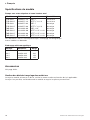
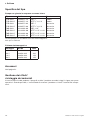
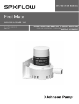
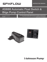
Tryck- och kapacitetsdata
(baserad på vatten vid 20°C, helkam och neoprenimpeller)
Pressure and capacity data
(based on water at 20°C/68°F, full cam and impeller neoprene)
Druck und Leistungsdaten
(basierend auf Wasser bei 20°C, 1/1 Kamm und Neoprenmpeller)
Pressions et débits
(eau à 20°C, came hauteur maxi et rotor néoprène)
Caudales y presiones
(con agua a 20°C, leva entera e impulsor de neopreno)
Dati di pressione e capacità
(per acqua a 20°C, camma intera e girante in neoprene)
F7B-5001
F8B-5001
700 rpm 900 rpm 1400 rpm 1750 rpm 2000 rpm
Bar kPa ft kW l/min USGPM kW l/min USGPM kW l/min USGPM kW l/min USGPM kW l/min USGPM
0,3 30 10,1 0,37 36,0 9,5 0,37 46,0 12,2 0,75 74,0 19,6 0,75 98,0 26,0 0,75 107, 0 28,3
0,6 60 20,1 0,37 34,0 9,0 0,37 44,0 11,6 0,75 72,0 19,0 0,75 96,0 25,4 0,75 104,0 2 7, 5
1,0 100 33,5 0,37 29,0 7,7 0,37 40,0 10,6 0,75 6 7, 0 1 7,7 0,75 8 7, 0 23,0 0,75 98,0 25,9
1,8 180 60,4 0,37 21,0 5,5 0,37 30,0 7, 9 0,75 5 7, 0 15,1 0,75 73,0 19,3 0,75 84,0 22,2
2,5 250 83,8 - - - - - - 0,75 37, 0 9,8 0,75 52,0 13,7 1,1 63,0 16,6
700 rpm 900 rpm 1400 rpm 1750 rpm 2000 rpm
Bar kPa ft kW l/min USGPM kW l/min USGPM kW l/min USGPM kW l/min USGPM kW l/min USGPM
0,3 30 10,1 0,37 87, 0 23,0 0,75 114,0 30,1 1,1 188,0 50,0 1,5 241,0 63,7 1,5 279,0 73,7
0,6 60 20,1 0,55 80,0 21,1 0,75 10 7, 0 28,3 1,1 180,0 4 7, 6 1,5 233,0 61,6 1,5 270,0 71,3
1,0 100 33,5 0,55 73,0 19,3 0,75 101,0 26,7 1,1 177,0 46,8 1,5 228,0 60,2 1,5 264,0 69,7
1,8 180 60,4 - - - 1,1 70,0 18,5 1,1 148,0 39,1 2,2 203,0 53,6 2,2 242,0 63,9
2,5 250 83,8 - - - - - - 1,1 108,0 28,5 2,2 166,0 43,9 2,2 208,0 55,0
Reducerad kam - 30-45% lägre kapacitet.
Nitrilimpeller - ca 30% lägre tryck.
Reduced cam - 30-45% lower capacity.
Impeller of nitrile - adjust total head approx. 30% down.
Mit reduziertem Kamm verringert sich die Leistung um 30-45%.
Mit Nitrilimpellers verrignert sich die Leistung um ca. 30%.
Came réduite - débit inférieur d’environ 30-45%.
Rotor en nitrile - hauteur de refoulement environ 30% inférieure.
Leva reducida - Reduce caudal 30-45%.
Impulsor de nitrilo - reduce la presión aproximadamente el 30%.
Camma ridotta - capacità inferiore del 30-45%.
Girante in nitrile - la prevalenza totale è inferiore del 30% circa.
15

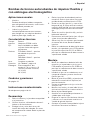
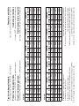
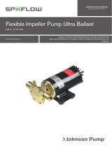
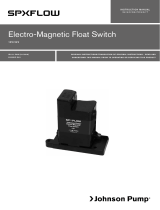
Reservdelslista
Parts list
Ersatzteilliste
Liste des pièces
Despiece
Elenco delle parti
F7B-5001/-50017
Lip seal
5
4
13
2
6 3 14 1 7 18 8 17
27
26
M
B-groove
A-groove
*Measure to the port
NP*
O
K J
L
11 18 9 25 1 23 24 22 15 19 20 21
16

10
F
E
A
B
F
ø H
G (2x)
D
T
C
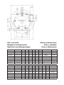
Vikt- och mått
Weights and dimensions
Gewichte und Abmessungen
Poids et dimensions
Peso y medidas
Peso e dimensioni
Type Art No A B C D E F G H
F7B-5001 10-24577-13 70 90 50 14,3 19,5 120 BSP1” 4x Ø9
F7B-50017 10-24577-19 70 90 50 14.3 23 120 NPTF 1”-11½ 4 x Ø9
F7B-5001 10-24577-99 70 90 50 14,3 19,5 120 BSP1” 4x Ø9
F7B-50017 10-24577-98 70 90 501 4.3 23 120 NPTF 1”-11½ 4 x Ø9
F8B-5001 10-13022-99 80 105 65 27 25 160 BSP 1½” 4 x Ø10.5
F8B-50017 10-13022-98 80 105 65 27 25 160 NPTF 1½”-11½ 4 x Ø10.5
F8B-50017 10-13022-96 114 140 65 27 25 160 NPTF 1½”-11½ 4 x Ø10.5
F8B-50017 10-13022-95 114 140 65 27 25 160 NPTF 1½”-11½ 4 x Ø10.5
Type Art No J K L M N O P T Weight/Peso
F7B-5001 10-24577-13 16 56 182 64 30 50 27 6 5.8 kg
F7B-50017 10-24577-19 16 56 182 64 30 50 27 6 5.8 kg
F7B-5001 10-24577-99 16 56 182 64 30 50 27 6 5.8 kg
F7B-50017 10-24577-98 16 56 182 64 30 50 27 6 5.8 kg
F8B-5001 10-13022-99 16 55 229 63 45 70 51 10 9.9 kg
F8B-50017 10-13022-98 16 55 229 63 45 70 51 10 9.9 kg
F8B-50017 10-13022-96 16 112 229 120 38 59 0.5 8 9.9 kg
F8B-50017 10-13022-95 16 112 229 120 38 59 0.5 8 9.9 kg
Measures in mm
17

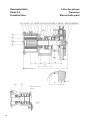
Reservdelslista
Parts list
Ersatzteilliste
Pos Nos Benämning Description Bezeichnung F7B-5001/-50017 F8B-5001/-50017
1 1 Pumphus Body Pumpengehäuse 01-24574-1 1) 01-13164-1 3)
1 Pumphus Body Pumpengehäuse 01-24574-2 2) 01-13164-2 4)
1 Pumphus Body Pumpengehäuse 01-24574-1 1) 01-13164-4 5)
1 Pumphus Body Pumpengehäuse 01-24574-2 2) 01-13164-3 6)
2 1 Axel Shaft Welle 01-46745 01-35136
3 1 Kam 1/1 Cam 1/1 Kamm 1/1 01-42679 01-42680
1 Kam 2/3 Cam 2/3 Kamm 2/3 01-42442 01-42425
4 1 Impeller Impeller Impeller 09-1028BT-1 (EPDM) 09-819B (neoprene)
1 Impeller Impeller Impeller 09-1028B-9 (nitrile) 09-819B-9 (nitrile)
5 1 Lock Endcover Deckel 01-46648-3 01-42422-1
6 1 Packning/o-ring Gasket Dichtung 0.2172.012 01-42424
7 1 Slitbricka Wear plate Schleissplatte 01-46798-2 01-42423
8 1 Stift Pin Stift 01-42400 01-42426
9 1 Distanshylsa Spacer Distanzhülse 01-46009 01-45374
10 2 Plugg Plug Stopfen - 0.2500.805
11 2 Kullager Ball bearing Kugellager 0.3431.742 0.3431.780
12 1 Låsring Retaining ring Sicherungsring 0.0371.040 0.0371.062
13 Skruv Screw Schraube 0.0279.301 (6 pcs) 0.0138.134(5 pcs)
14 1 Kamskruv 1/1 Cam screw 1/1 Kammschraube 1/1 01-46794-01 01-46794-02
1 Kamskruv 2/3 Cam screw 2/3 Kammschraube 2/3 01-46794-07 01-46794-02
15 1 Kil Key Keil 0.0502.001 0.0502.001
16 1 Läpptätning Lip seal Lippendichtung 0.2233.012 0.2233.015
17 1 Mekanisk tätning Mechanical seal Gleitringdichtung 0.2247.022 0.2247.008
18 Låsring Retaining ring Sicherungsring 0.0370.017 (1 pc) 0.0370.525 (2 pcs)
19 1 Bricka Washer Scheibe 0.0353.309 0.0353.309
20 1 Bricka Washer Scheibe 01-46789-06 01-46789-06
21 1 Skruv Screw Schraube 0.0141.918 0.0141.918
22 1 Koppling Clutch Kupplung
12 V, 2xA-spår 12 V, 2xA-groove 12 V, 2xA-Profil 0.3454.001 0.3454.001
24 V, 2xA-spår 24 V, 2xA-groove 24 V, 2xA-Profil 0.3454.002 0.3454.002
12 V, 1xB-spår 12 V, 1xB-groove 12 V, 1xB-Profil 0.3454.003 0.3454.003
24 V, 1xB-spår 24 V, 1xB-groove 24 V, 1xB-Profil 0.3454.004 0.3454.004
23 3 Bricka Washer Scheibe - 0.0353.402
24 3 Skruv Screw Schraube 0.0141.903 0.0141.903
25 1 Fästring Adaptor ring Befestigungsring - 01-35144-2
26 3 Skruv Screw Schraube - 0.0300.565
27 1 O-ring O-ring O-Ring 0.2173.402 0.2172.573
28 1 Bricka Washer Scheibe - -
29 1 Bricka Washer Scheibe 01-45191 -
*) 1 Service kit Service kit Servicesatz 09-47427 (EPDM)
09-46868 (nitrile)
09-45575 (neoprene)
09-45576 (nitrile)
**) 1 Service kit Service kit Servicesatz 09-47426 (EPDM)
09-45593 (nitrile)
09-45577 (neoprene)
09-45578 (nitrile)
***) 1 Monteringssats
koppling
Mounting kit
for clutch
Montagesatz
für Kupplung
09-46436 09-46437
*) pos 4, 6, 13, 17 **) pos 4, 6, 13, 16 ***) pos 15, 19, 20, 21, 24, 23/29 1) BSP 1” – pump 10-24577-13/-99
2) NPTF 1”-11½ – pump 10-24577-19/-98 3) BSP 1½” – pump 10-13022-99 4) NPTF 1½”-11½ – pump 10-13022-98
5) NPTF 1½”-11½ – pump 10-13022-96 6) NPTF 1¼”-11½ – pump 10-13022-95
18

Liste des pièces
Lista de piezas
Elenco delle parti
Pos Nos Description Descripción Descrizione F7B-5001/-50017 F8B-5001/-50017
1 1 Corps Cuerpo Corpo 01-24574-1 1) 01-13164-1 3)
1 Corps Cuerpo Corpo 01-24574-2 2) 01-13164-2 4)
1 Corps Cuerpo Corpo 01-24574-1 1) 01-13164-4 5)
1 Corps Cuerpo Corpo 01-24574-2 2) 01-13164-3 6)
2 1 Arbre Eje Albero 01-46745 01-35136
3 1 Came 1/1 Leva 1/1 Camma 1/1 01-42679 01-42680
1 Came 2/3 Leva 2/3 Camma 2/3 01-42442 01-42425
4 1 Rotor Impulsor Girante 09-1028BT-1 (EPDM) 09-819B (neoprene)
1 Rotor Impulsor Girante 09-1028B-9 (nitrile) 09-819B-9 (nitrile)
5 1 Couvercle Tapa Coperchio 01-46648-3 01-42422-1
6 1 Joint/Joint torique Junta/Aro tórico Guarnizione coperchio/O-Ring 0.2172.012 01-42424
7 1 Plaque d’usure Platina Placca d’usura 01-46798-2 01-42423
8 1 Ergot Cabilla Spina 01-42400 01-42426
9 1 Entretoise Separador Spessore 01-46009 01-45374
10 2 Bouchon Tapón Presa - 0.2500.805
11 2 Roulements à billes Cojinetes Cuscinetto 0.3431.742 0.3431.780
12 1 Circlips Anillo de fijación Anello di fermo 0.0371.040 0.0371.062
13 Vis Tornillo Vite 0.0279.301 (6 pcs) 0.0138.134(5 pcs)
14 1 Vis de came 1/1 Tornillo leva Vite camma 1/1 01-46794-01 01-46794-02
1 Vis de came 2/3 Tornillo 2/3 Vite camma 2/3 01-46794-07 01-46794-02
15 1 Clavette Chaveta Chiavella 0.0502.001 0.0502.001
16 1 Joint à lèvre Retén labial Corteco 0.2233.012 0.2233.015
17 1 Garniture mécanique Retén mecánico Tenuta meccanica 0.2247.022 0.2247.008
18 Circlips Anillo fijación Anello di fermo 0.0370.017 (1 pc) 0.0370.525 (2 pcs)
19 1 Rondelle Arandela Rondella 0.0353.309 0.0353.309
20 1 Rondelle Arandela Rondella 01-46789-06 01-46789-06
21 1 Vis Tornillo Vite 0.0141.918 0.0141.918
22 1 Embrayage Embrague Puleggia
12 V, 2 gorges A 12 V, 2 x A canales 12 V, gola 2xA 0.3454.001 0.3454.001
24 V, 2 gorges A 24 V, 2 x A canales 24 V, gola 2xA 0.3454.002 0.3454.002
12 V, 1 gorge B 12 V, 1 x B canal 12 V, gola 1xB 0.3454.003 0.3454.003
24 V, 1 gorge B 24 V, 1 x B canal 24 V, gola 1xB 0.3454.004 0.3454.004
23 3 Rondelle Arandela Rondella - 0.0353.402
24 3 Vis Tornillo Vite 0.0141.903 0.0141.903
25 1 Adapteur Brida Corpo pompa - 01-35144-2
26 3 Vis Tornillo Vite - 0.0300.565
27 1 Joint torique Aro tórico O-Ring 0.2173.402 0.2172.573
28 1 Rondelle Arandela Rondella - -
29 1 Rondelle Arandela Vite 01-45191 -
*) 1 Kit de réparation Juego recambios Kit di servizio 09-47427 (EPDM)
09-46868 (nitrile)
09-45575 (neoprene)
09-45576 (nitrile)
**) 1 Kit de réparation Juego recambios Kit di servizio 09-47426 (EPDM)
09-45593 (nitrile)
09-45577 (neoprene)
09-45578 (nitrile)
***) 1 Kit de montage pour
embrayage
Recambios
embrague
Kit di assemblaggio
per frizione
09-46436 09-46437
*) pos 4, 6, 13, 17 **) pos 4, 6, 13, 16 ***) pos 15, 19, 20, 21, 24, 23/29 1) BSP 1” – pump 10-24577-13/-99
2) NPTF 1”-11½ – pump 10-24577-19/-98 3) BSP 1½” – pump 10-13022-99 4) NPTF 1½”-11½ – pump 10-13022-98
5) NPTF 1½”-11½ – pump 10-13022-96 6) NPTF 1¼”-11½ – pump 10-13022-95
19

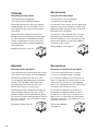
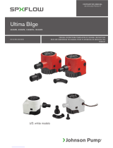
Tillbehör
Vakuumbrytare 09-45053
• För automatisk avstängning.
• För att förhindra skada på pumpen.
Vakuumbrytaren passar alla självsugande
impellerpumpar och ska användas vid t ex
länsning/tömning av tank för att förhindra
torrkörning.
Vakuumbrytaren stänger automatiskt av
pumpen när kölsvinet/tanken är tömd. Med
en vakuumbrytare installerad kan pumpen
startas antingen genom fjärrstyrning eller
manuellt genom att trycka på knappen på
vakuumbrytaren.
Kopplingsschema, se sid 21.
Zubehör
Vakuumschalter 09-45053
• Zum automatischen Abschalten der Pumpe.
• Zum Schutz der Pumpe vor Beschädigung.
Der Vakuumschalter kann bei allen selb-
stansaugenden Impellerpumpen eingesetzt
werden. Z.B. bei Bilge- oder Tankentle-
erungspumpen dient der Schalter zum
Schutz der Pumpe vor Trockenlauf.
Der Vakuumschalter schaltet die Pumpe ab,
wenn die Bilge oder der Tank leer ist. Mit
dem am Vakuumschalter befindlichen Schal-
ter kann die Pumpe entwerder durch Drücken
des Druckschalters oder des Hebels wieder
gestartet werden.
Schaltplan, Siehe Seite 21.
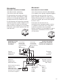
Accessories
Vacuum switch 09-45053
• For automatic shut off operation.
• To prevent pump damage.
The vacuum switch works with all selfpriming
impeller pumps and should be used for e.g.
bilge pumping/emptying of tanks to prevent
the pump from running dry.
The vacuum switch automatically shuts the
pump off when the bilge/tank is dry. With
the switch fitted, you can start the pump by
remote push button or manually by depres-
sing lever on the switch.
Wiring diagram, see page 21.
Accessoires
Contacteur à dépression 09-45053
• Pour arrêt automatique de la pompe.
• Pour éviter d’endommager la pompe.
Le contacteur à dépression fonctionne sur
toutes les pompes auto-amorçantes à rotor
et devrait être utilisé pour le pompage de
cales ou la vidange de réservoirs afin d’éviter
à la pompe de fonctionner à sec.
Le contacteur à dépression arrête auto-
matiquement la pompe quand la cale ou
le réservoir est vide. Avec le contacteur à
dépression, il est possible de commander
la pompe à distance ou en appuyant sur le
levier du contacteur.
Schéma de câblage,
voir page 21.
20
La page est en cours de chargement...
La page est en cours de chargement...
La page est en cours de chargement...
La page est en cours de chargement...
-
 1
1
-
 2
2
-
 3
3
-
 4
4
-
 5
5
-
 6
6
-
 7
7
-
 8
8
-
 9
9
-
 10
10
-
 11
11
-
 12
12
-
 13
13
-
 14
14
-
 15
15
-
 16
16
-
 17
17
-
 18
18
-
 19
19
-
 20
20
-
 21
21
-
 22
22
-
 23
23
-
 24
24


SPX FLOW Heavy Duty Electro-Magnetic Clutch Pump FB-5001 Series Manuel utilisateur
- Taper
- Manuel utilisateur
dans d''autres langues
Documents connexes
-
 SPX FLOW Vacuum Switch Manuel utilisateur
-
 SPX FLOW Bilge, Deck Wash and Refueling pump Manuel utilisateur
-
 SPX FLOW Original Impeller Kit Manuel utilisateur
-
 SPX FLOW First Mate Manuel utilisateur
-
 SPX FLOW Ultra Ballast Pump Manuel utilisateur
-
 SPX FLOW Ultima Bilge 1250GPH Manuel utilisateur
-
 SPX FLOW Control Panel Manuel utilisateur
-
 SPX FLOW Bilge Pump Float Switche Mode d'emploi
-
 SPX FLOW Bilge Pump Float Switche Mode d'emploi
-
 SPX FLOW C090 Manuel utilisateur


Autres documents
-
Milnor MWF125J7 Le manuel du propriétaire
-
Moulinex OX678E00 Le manuel du propriétaire
-
ABB TA 450 SU V1000 Operating Instructions Manual
-
Philips SHE4500/10 Product Datasheet
-
Kyosho REFLEX XTR 5.04 Flight Simulator(Windows Vista compatible) Manuel utilisateur
-
Socomec DIRIS A80 Mode d'emploi
-
Electrolux FHK50-3T Manuel utilisateur
-
Lego 7685 City Le manuel du propriétaire
-
-
Nilfisk-ALTO RS 501 Manuel utilisateur