DeWalt DWE7491RS Manuel utilisateur
- Catégorie
- Outils électroportatifs
- Taper
- Manuel utilisateur

If you have questions or comments, contact us.
Pour toute question ou tout commentaire, nous contacter.
Si tiene dudas o comentarios, contáctenos.
1-800-4-DeWALT
Instruction Manual
Guide D’utilisation
Manual de instrucciones
Final Page Size: 8.5 x 11in
DWE7491
Heavy-Duty 10" (254 mm) Job Site Table Saw
Scie de table industrielle de chantier de 254mm (10po)
Sierra de Banco para el Lugar de Trabajo de 254 mm (10") de Alta Resistencia

English (original instructions) 1
Français (traduction de la notice d’instructions originale) 15
Español (traducido de las instrucciones originales) 28

1
ENGLISH
English (original instructions)
Definitions: Safety Alert Symbols and Words
This instruction manual uses the following safety alert symbols and words to alert you to hazardous situations and your risk of personal injury or property damage.
DANGER: Indicates an imminently hazardous situation which, if not avoided, will result in death or seriousinjury.
WARNING: Indicates a potentially hazardous situation which, if not avoided, could result in death or seriousinjury.
CAUTION: Indicates a potentially hazardous situation which, if not avoided, may result in minor or moderateinjury.
(Used without word) Indicates a safety related message.
NOTICE: Indicates a practice not related to personal injury which, if not avoided, may result in propertydamage.
WARNING! Read all safety warnings and all
instructions. Failure to follow the warnings and
instructions may result in electric shock, fire and/or
seriousinjury.
WARNING: To reduce the risk of injury, read the
instructionmanual.
If you have any questions or comments about this or any
DeWALT
tool, call us toll free at:
1-800-4-
DeWALT
(1-800-433-9258).
1
Table
2
Blade
3
Rip scale indicator
4
Fine adjust knob
5
Rail lock lever
6
Blade height adjustment wheel
7
Bevel lock lever
8
ON/OFF switch
9
Mounting holes
10
Miter gauge
11
Blade guard assembly
12
Riving knife/blade guard release lever
13
Splitter
14
Anti-kickback assembly
15
Dust collection port
16
Guard dust collection port
17
Throat plate
18
Rip fence
19
Rip fence latch
20
Work support/narrrow rip fence (stored position)
21
Blade wrenches (stored position) (non thru-sawing)
22
Push stick (stored position) (non thru-sawing)
23
Riving knife (stored position) (non thru-sawing)
Fig. A
19
20
23
22
21
15
13
16
14
2
9
1117
1
12
3
5
4
19
20
18
6
78
10
SPECIFICATIONS
Amperes 15 A
Table Size 21–7/8" (556 mm) X 26–3/8" (669 mm)
Miter Angle 30° L&R
Bevel Angle 0° to 45°L
Blade Size 10" (254 mm)
Max. Cut Depth 0° Bevel, 3–1/8" (79 mm)
Max. Cut Depth 45° Bevel, 2–1/4" (57 mm)
RPM, no load 4800
Weight >55.2 lbs. (>25 Kg)

2
ENGLISH
General Power Tool Safety Warnings
WARNING: Read all safety warnings, instructions, illustrations and specifications
provided with this power tool. Failure to follow all instructions listed below may result in
electric shock, fire and/or seriousinjury.
SAVE ALL WARNINGS AND INSTRUCTIONS
FOR FUTURE REFERENCE
The term “power tool” in the warnings refers to your mains-operated (corded) power tool or battery-
operated (cordless) powertool.
1) Work area safety
a ) Keep work area clean and well lit. Cluttered or dark areas inviteaccidents.
b ) Do not operate power tools in explosive atmospheres, such as in the presence of
flammable liquids, gases or dust. Power tools create sparks which may ignite the dust
orfumes.
c ) Keep children and bystanders away while operating a power tool. Distractions can
cause you to losecontrol.
2) Electrical safety
a ) Power tool plugs must match the outlet. Never modify the plug in any way. Do not
use any adapter plugs with earthed (grounded) power tools. Unmodified plugs and
matching outlets will reduce risk of electricshock.
b ) Avoid body contact with earthed or grounded surfaces such as pipes, radiators,
ranges and refrigerators. There is an increased risk of electric shock if your body is earthed
orgrounded.
c ) Do not expose power tools to rain or wet conditions. Water entering a power tool will
increase the risk of electricshock.
d ) Do not abuse the cord. Never use the cord for carrying, pulling or unplugging the
power tool. Keep cord away from heat, oil, sharp edges or moving parts. Damaged
or entangled cords increase the risk of electricshock.
e ) When operating a power tool outdoors, use an extension cord suitable for outdoor
use. Use of a cord suitable for outdoor use reduces the risk of electricshock.
f ) If operating a power tool in a damp location is unavoidable, use a residual current
device (RCD) protected supply. Use of an RCD reduces the risk of electricshock.
3) Personal safety
a ) Stay alert, watch what you are doing and use common sense when operating a
power tool. Do not use a power tool while you are tired or under the influence of
drugs, alcohol or medication. A moment of inattention while operating power tools may
result in serious personalinjury.
b ) Use personal protective equipment. Always wear eye protection. Protective
equipment such as dust mask, non-skid safety shoes, hard hat, or hearing protection used for
appropriate conditions will reduce personalinjuries.
c ) Prevent unintentional starting. Ensure the switch is in the off position before
connecting to power source and/or battery pack, picking up or carrying the tool.
Carrying power tools with your finger on the switch or energising power tools that have the
switch on invitesaccidents.
d ) Remove any adjusting key or wrench before turning the power tool on. A wrench or a
key left attached to a rotating part of the power tool may result in personalinjury.
e ) Do not overreach. Keep proper footing and balance at all times. This enables better
control of the power tool in unexpectedsituations.
f ) Dress properly. Do not wear loose clothing or jewellery. Keep your hair, clothing
and gloves away from moving parts. Loose clothes, jewellery or long hair can be caught
in movingparts.
g ) If devices are provided for the connection of dust extraction and collection facilities,
ensure these are connected and properly used. Use of dust collection can reduce dust-
relatedhazards.
h ) Do not let familiarity gained from frequent use of tools allow you to become
complacent and ignore tool safety principles. A careless action can cause severe injury
within a fraction of asecond.
4) Power tool use and care
a ) Do not force the power tool. Use the correct power tool for your application. The
correct power tool will do the job better and safer at the rate for which it wasdesigned.
b ) Do not use the power tool if the switch does not turn it on and off. Any power tool that
cannot be controlled with the switch is dangerous and must berepaired.
c ) Disconnect the plug from the power source and/ or remove the battery pack,
if detachable, from the power tool before making any adjustments, changing
accessories, or storing power tools. Such preventive safety measures reduce the risk of
starting the power toolaccidentally.
d ) Store idle power tools out of the reach of children and do not allow persons
unfamiliar with the power tool or these instructions to operate the power tool.
Power tools are dangerous in the hands of untrainedusers.
e ) Maintain power tools and accessories. Check for misalignment or binding of
moving parts, breakage of parts and any other condition that may affect the
power tool’s operation. If damaged, have the power tool repaired before use.
Many accidents are caused by poorly maintained powertools.
f ) Keep cutting tools sharp and clean. Properly maintained cutting tools with sharp cutting
edges are less likely to bind and are easier tocontrol.
g ) Use the power tool, accessories and tool bits etc., in accordance with these
instructions taking into account the working conditions and the work to be
performed. Use of the power tool for operations different from those intended could result
in a hazardoussituation.
h ) Keep handles and grasping surfaces dry, clean and free from oil and grease. Slippery
handles and grasping surfaces do not allow for safe handling and control of the tool in
unexpectedsituations.
5) Service
a ) Have your power tool serviced by a qualified repair person using only identical
replacement parts. This will ensure that the safety of the power tool ismaintained.
Safety Instructions for Table Saws
1) Guarding Related Warnings
a ) Keep guards in place. Guards must be in working order and be properly mounted. A
guard that is loose, damaged, or is not functioning correctly must be repaired orreplaced.
b ) Always use saw blade guard, riving knife and anti-kickback pawls for every
through-cutting operation. For through-cutting operations where the saw blade cuts
completely through the thickness of the workpiece, the guard and other safety devices help
reduce the risk ofinjury.
c ) Immediately reattach the guarding system after completing an operation (such
as rabbeting cuts) which requires removal of the guard, riving knife and/or anti-
kickback device. The guard, riving knife, and anti-kickback device help to reduce the risk
ofinjury.
d ) Make sure the saw blade is not contacting the guard, riving knife or the workpiece
before the switch is turned on. Inadvertent contact of these items with the saw blade
could cause a hazardouscondition.
e ) Adjust the riving knife as described in this instruction manual. Incorrect spacing,
positioning and alignment can make the riving knife ineffective in reducing the likelihood
ofkickback.
f ) For the riving knife and anti-kickback pawls to work, they must be engaged in the
workpiece. The riving knife and anti-kickback pawls are ineffective when cutting workpieces
that are too short to be engaged with the riving knife and anti-kickback pawls. Under these
conditions a kickback cannot be prevented by the riving knife and anti-kickbackpawls.
g ) Use the appropriate saw blade for the riving knife. For the riving knife to function
properly, the saw blade diameter must match the appropriate riving knife and the body of
the saw blade must be thinner than the thickness of the riving knife and the cutting width of
the saw blade must be wider than the thickness of the rivingknife.
2) Cutting Procedures Warnings
a ) DANGER: Never place your fingers or hands in the vicinity or in line with the
saw blade. A moment of inattention or a slip could direct your hand towards the
saw blade and result in serious personalinjury.
b ) Feed the workpiece into the saw blade or cutter only against the direction of
rotation. Feeding the workpiece in the same direction that the saw blade is rotating above
the table may result in the workpiece, and your hand, being pulled into the sawblade.
c ) Never use the miter gauge to feed the workpiece when ripping and do not use the
rip fence as a length stop when cross cutting with the miter gauge. Guiding the
workpiece with the rip fence and the miter gauge at the same time increases the likelihood of
saw blade binding andkickback.
d ) When ripping, always apply the workpiece feeding force between the fence and the
saw blade. Use a push stick when the distance between the fence and the saw blade
is less than 5.9" (150 mm), and use a push block when this distance is less than 2"
(50 mm). "Work helping" devices will keep your hand at a safe distance from the sawblade.
e ) Use only the push stick provided by the manufacturer or constructed in accordance
with the instructions. This push stick provides sufficient distance of the hand from the
sawblade.
f ) Never use a damaged or cut push stick. A damaged push stick may break causing your
hand to slip into the sawblade.
g ) Do not perform any operation "freehand". Always use either the rip fence or the
miter gauge to position and guide the workpiece. "Freehand" means using your
hands to support or guide the workpiece, in lieu of a rip fence or miter gauge.
Freehand sawing leads to misalignment, binding andkickback.
h ) Never reach around or over a rotating saw blade. Reaching for a workpiece may lead to
accidental contact with the moving sawblade.
i ) Provide auxiliary workpiece support to the rear and/or sides of the saw table
for long and/or wide workpieces to keep them level. A long and/or wide workpiece
has a tendency to pivot on the table’s edge, causing loss of control, saw blade binding
andkickback.
j ) Feed workpiece at an even pace. Do not bend or twist the workpiece. If jamming
occurs, turn the tool off immediately, unplug the tool then clear the jam. Jamming
the saw blade by the workpiece can cause kickback or stall themotor.

3
ENGLISH
k ) Do not remove pieces of cut-off material while the saw is running. The material
may become trapped between the fence or inside the saw blade guard and the saw
blade pulling your fingers into the saw blade. Turn the saw off and wait until the saw
blade stops before removingmaterial.
l ) Use an auxiliary fence in contact with the table top when ripping workpieces less
than (2 mm) thick. A thin workpiece may wedge under the rip fence and create akickback.
3) Kickback Causes and Related Warnings
Kickback is a sudden reaction of the workpiece due to a pinched, jammed saw blade or misaligned
line of cut in the workpiece with respect to the saw blade or when a part of the workpiece binds
between the saw blade and the rip fence or other fixedobject.
Most frequently during kickback, the workpiece is lifted from the table by the rear portion of the saw
blade and is propelled towards theoperator.
Kickback is the result of saw misuse and/or incorrect operating procedures or conditions and can be
avoided by taking proper precautions as givenbelow.
a ) Never stand directly in line with the saw blade. Always position your body on the
same side of the saw blade as the fence. Kickback may propel the workpiece at high
velocity towards anyone standing in front and in line with the sawblade.
b ) Never reach over or in back of the saw blade to pull or to support the workpiece.
Accidental contact with the saw blade may occur or kickback may drag your fingers into the
sawblade.
c ) Never hold and press the workpiece that is being cut off against the rotating saw
blade. Pressing the workpiece being cut off against the saw blade will create a binding
condition andkickback.
d ) Align the fence to be parallel with the saw blade. A misaligned fence will pinch the
workpiece against the saw blade and createkickback.
e ) Use a featherboard to guide the workpiece against the table and fence when
making non-through cuts such as rabbeting cuts. A featherboard helps to control the
workpiece in the event of akickback.
f ) Support large panels to minimize the risk of saw blade pinching and kickback.
Large panels tend to sag under their own weight. Support(s) must be placed under all
portions of the panel overhanging the tabletop.
g ) Use extra caution when cutting a workpiece that is twisted, knotted, warped or
does not have a straight edge to guide it with a miter gauge or along the fence. A
warped, knotted, or twisted workpiece is unstable and causes misalignment of the kerf with
the saw blade, binding andkickback.
h ) Never cut more than one workpiece, stacked vertically or horizontally. The saw blade
could pick up one or more pieces and causekickback.
i ) When restarting the saw with the saw blade in the workpiece, center the saw blade
in the kerf so that the saw teeth are not engaged in the material. If the saw blade
binds, it may lift up the workpiece and cause kickback when the saw isrestarted.
j ) Keep saw blades clean, sharp, and with sufficient set. Never use warped saw blades
or saw blades with cracked or broken teeth. Sharp and properly set saw blades minimize
binding, stalling andkickback.
4) Table Saw Operating Procedure Warnings
a ) Turn off the table saw and disconnect from the power source when removing the
table insert, changing the saw blade or making adjustments to the riving knife,
anti-kickback pawls or saw blade guard, and when the machine is left unattended.
Precautionary measures will avoidaccidents.
b ) Never leave the table saw running unattended. Turn it off and don’t leave the tool
until it comes to a complete stop. An unattended running saw is an uncontrolledhazard.
c ) Locate the table saw in a well-lit and level area where you can maintain good
footing and balance. It should be installed in an area that provides enough room
to easily handle the size of your workpiece. Cramped, dark areas, and uneven slippery
floors inviteaccidents.
d ) Frequently clean and remove sawdust from under the saw table and/or the dust
collection device. Accumulated sawdust is combustible and may self-ignite.
e ) The table saw must be secured. A table saw that is not properly secured may move or
tipover.
f ) Remove tools, wood scraps, etc. from the table before the table saw is turned on.
Distraction or a potential jam can bedangerous.
g ) Always use saw blades with correct size and shape (diamond versus round) of
arbour holes. Saw blades that do not match the mounting hardware of the saw will run
off-center, causing loss ofcontrol.
h ) Never use damaged or incorrect saw blade mounting means such as flanges, saw
blade washers, bolts or nuts. These mounting means were specially designed for your
saw, for safe operation and optimumperformance.
i ) Never stand on the table saw, do not use it as a stepping stool. Serious injury could
occur if the tool is tipped or if the cutting tool is accidentallycontacted.
j ) Make sure that the saw blade is installed to rotate in the proper direction. Do not
use grinding wheels, wire brushes, or abrasive wheels on a table saw. Improper saw
blade installation or use of accessories not recommended may cause seriousinjury.
Additional Safety Rules for Table Saws
WARNING: Cutting plastics, sap coated wood, and other materials may cause melted
material to accumulate on the blade tips and the body of the saw blade, increasing the risk
of blade overheating and binding whilecutting.
• Avoid awkward positions, where a sudden slip could cause a hand to move into a sawblade.
• Do not attempt to retrieve materials near the blade on the saw table while the blade isspinning.
• Never reach in back of, or around, the cutting tool with either hand to hold down
theworkpiece.
• Keep Arms, Hands and fingers away from the blade to prevent seriousinjury.
• Use a push stick that is appropriate to the application to push workpieces through the
saw. A push stick is a wooden or plastic stick, often homemade, that should be used whenever
the size or shape of the workpiece would cause you to place your hands within 6" (152mm) of
theblade.
• Use hold-downs, jigs, fixtures or feather boards to help guide and control the
workpiece. Accessories for use with your tool are available at extra cost from your local dealer
or authorized service center. Instructions for making a push stick, a narrow rip auxiliary fence, a
push block and feather boards are included in thismanual.
• Do not perform ripping, crosscutting or any other operationfreehand.
• NEVER reach around or over sawblade while the blade isspinning.
• Stability. Make sure the table saw is firmly mounted to a secure surface before use and does
notmove.
• The table saw should only be set up on a level and stable surface. The work area should be
free from obstructions and trip hazards. No materials or tools should be leaned against thesaw.
• Never cut metals, cement board or masonry. Certain man-made materials have special
instructions for cutting on table saws. Follow the manufacturer’s recommendations at all times.
Damage to the saw and personal injury mayresult.
• Do not install a diamond masonry blade and attempt to use the table saw as a wetsaw.
• The proper throat plate must be locked in place at all times to reduce the risk of a thrown
workpiece and possibleinjury.
• Wear gloves when handling sawblades.
• Use the correct saw blade for the intended operation. The blade must rotate toward the
front of the saw. Always tighten the blade arbor nut securely. Before use, inspect the blade for
cracks or missing teeth. Do not use a damaged or dullblade.
• Never attempt to free a stalled saw blade without first turning the machine off and
disconnect the plug from the power source. If a workpiece or cut-off piece becomes trapped
inside the blade guard assembly, turn saw off and wait for blade to stop before lifting the blade
guard assembly and removing thepiece.
• Never Start The Machine with the workpiece against the blade to reduce the risk of a thrown
workpiece and personalinjury.
• Do Not Have Any Part Of Your Body In Line With The Blade. Personal injury may occur.
Stand to either side of theblade.
• Never Perform Layout, Assembly Or Set-Up Work on the table/work area when the machine
is running. A sudden slip could cause a hand to move into the blade. Severe injury canresult.
• Never perform any adjustments while the saw is running such as fence repositioning or
removal, bevel lock adjustment, or blade heightadjustment.
• Clean the table/work area before leaving the machine. Lock the switch in the “OFF”
position and disconnect the plug from the power source to prevent unauthorizeduse.
• ALWAYS lock the fence and bevel adjustment beforecutting.
• Avoid overheating the saw blade tips. Keep material moving and parallel with the fence. Do
not force work into theblade.
• If cutting plastic materials, avoid melting theplastic.
• DO NOT leave a long board (or other workpiece) unsupported so the spring of the board
causes it to shift on the table resulting in loss of control and possible injury. Provide
proper support for the workpiece, based on its size and the type of operation to be performed.
Hold the work firmly against the fence and down against the tablesurface.
• If this saw makes an unfamiliar noise or if it vibrates excessively, cease operating immediately,
turn unit off and disconnect from the plug from the power source until the problem has been
located and corrected. Contact a
DeWALT
factory service center, a
DeWALT
authorized service
center or other qualified service personnel if the problem can not befound.
• Do not operate this machine until it is completely assembled and installed according to the
instructions. A machine incorrectly assembled can cause seriousinjury.
• NEVER attempt to cut a stack of loose pieces of material which could cause loss of control or
kickback. Support all materialssecurely.
Saw Blades
• Do not use saw blades that do not conform to the dimensions stated in the Specifications. Do
not use any spacers to make a blade fit onto the spindle. Use only the blades specified in this
manual, complying with EN847-1, if intended for wood and similarmaterials.
• Consider applying specially designed noise-reductionblades.
• Do not use high steel (HS) sawblades.
• Do not use cracked or damaged sawblades.
• Ensure that the chosen saw blade is suitable for the material to becut.

4
ENGLISH
• Always wear gloves for handling saw blades and rough material. Saw blades should be carried in
a holder whereverpracticable.
Additional Safety Information
WARNING: ALWAYS use safety glasses. Everyday eyeglasses are NOT safety glasses.
Also use face or dust mask if cutting operation is dusty. ALWAYS WEAR CERTIFIED
SAFETYEQUIPMENT:
• ANSI Z87.1 eye protection (CAN/CSA Z94.3),
• ANSI S12.6 (S3.19) hearing protection,
• NIOSH/OSHA/MSHA respiratoryprotection.
WARNING: Some dust created by power sanding, sawing, grinding, drilling, and other
construction activities contains chemicals known to the State of California to cause cancer,
birth defects or other reproductive harm. Some examples of these chemicalsare:
• lead from lead-based paints,
• crystalline silica from bricks and cement and other masonry products, and
• arsenic and chromium from chemically-treatedlumber.
Your risk from these exposures varies, depending on how often you do this type of work. To reduce
your exposure to these chemicals: work in a well ventilated area, and work with approved safety
equipment, such as those dust masks that are specially designed to filter out microscopicparticles.
• Avoid prolonged contact with dust from power sanding, sawing, grinding, drilling, and
other construction activities. Wear protective clothing and wash exposed areas with
soap and water. Allowing dust to get into your mouth, eyes, or lay on the skin may promote
absorption of harmfulchemicals.
WARNING: Use of this tool can generate and/or disperse dust, which may cause serious
and permanent respiratory or other injury. Always use NIOSH/OSHA approved respiratory
protection appropriate for the dust exposure. Direct particles away from face andbody.
WARNING: Always wear proper personal hearing protection that conforms to ANSI
S12.6 (S3.19) during use. Under some conditions and duration of use, noise from this
product may contribute to hearingloss.
• Air vents often cover moving parts and should be avoided. Loose clothes, jewelry or long
hair can be caught in movingparts.
• An extension cord must have adequate wire size (AWG or American Wire Gauge) for
safety. The smaller the gauge number of the wire, the greater the capacity of the cable, that is,
16 gauge has more capacity than 18 gauge. An undersized cord will cause a drop in line voltage
resulting in loss of power and overheating. When using more than one extension to make up
the total length, be sure each individual extension contains at least the minimum wire size. The
following table shows the correct size to use depending on cord length and nameplate ampere
rating. If in doubt, use the next heavier gauge. The lower the gauge number, the heavier thecord.
Minimum Gauge for Cord Sets
Volts Total Length of Cord in Feet (meters)
120 V 25 (7.6) 50 (15.2) 100 (30.5) 150 (45.7)
240 V 50 (15.2) 100 (30.5) 200 (61.0) 300 (91.4)
Ampere Rating
American Wire Gauge
More Than Not More
Than
0 6 18 16 16 14
6 10 18 16 14 12
10 12 16 16 14 12
12 16 14 12 Not Recommended
The label on your tool may include the following symbols. The symbols and their definitions are
asfollows:
V ......................... volts
Hz .......................hertz
min ..................... minutes
or DC ......direct current
...................... Class I Construction (grounded)
…/min ..............per minute
BPM .................... beats per minute
IPM ..................... impacts per minute
RPM .................... revolutions per minute
sfpm ................... surface feet per minute
SPM .................... strokes per minute
A ......................... amperes
W ........................watts
kg ........................kilograms
mm .....................millimeters
or AC ...........alternating current
or AC/DC .... alternating or direct current
...................... Class II Construction (double insulated)
n
o
.......................no load speed
n .........................rated speed
......................earthing terminal
.....................safety alert symbol
.....................visible radiation
..................... wear respiratory protection
..................... wear eye protection
..................... wear hearing protection
..................... read all documentation
SAVE THESE INSTRUCTIONS FOR
FUTURE USE
Motor
Be sure your power supply agrees with the nameplate marking. Voltage decrease of more than
10% will cause loss of power and overheating.
DeWALT
tools are factory tested; if this tool does
not operate, check power supply.
COMPONENTS (FIG. A)
WARNING: Never modify the power tool or any part of it. Damage or personal injury
couldresult.
Refer to Figure A to become familiar with the saw and its various parts. The following sections
on assembly and adjustments will refer to these terms and you must know what and where the
parts are.
Intended Use
This table saw is designed for professional ripping, crosscutting, mitering, beveling and non thru-
cutting applications, such as dadoing, with various materials.
DO NOT use for cutting metal, cement board, or masonry.
DO NOT use under wet conditions or in presence of flammable liquids or gases.
DO NOT let children come into contact with the tool. Supervision is required when
inexperienced operators use this tool.
DO NOT use shaping cutter heads on this saw.
DO NOT perform tapered cuts without a tapered jig accessory.
DO NOT use the saw for plunge or cove cutting.
Unpacking (Fig. B)
WARNING: To reduce the risk of injury, DO NOT connect the machine to the power source
until the table saw is completely assembled and you have read the entire instruction manual.
Open the box and slide the saw out, as shown in FigureB.
Carefully unpack the table saw and all loose items from the carton. Examine all parts to make sure
that parts have not been damaged during shipping. If any parts are missing or damaged, contact
your dealer to replace them before attempting to assemble the tool.
Fig. B
ASSEMBLY
WARNING: Shock Hazard. To reduce the risk of serious personal injury, turn unit off
and disconnect machine from power source before attempting to move it, change
accessories or make any adjustments. An accidental start-up can cause injury.
This Saw should be Assembled in the Following Order: (Fig. C, D)
1. Unlock and remove the throat plate
17
. Refer to Removing the Throat Plate section.
2. Make sure blade is installed correctly and arbor nut is tight. Use wrenches
21
stored on the
tool. Refer to FigureD.
3. Install and lock throat plate
17
. (NOTE: Adjust leveling screws before proceeding. Refer to To
Assemble the Throat Plate.)
4. Attach the rip fence
18
. (NOTE: Adjust rip scale before proceeding. Refer to Adjusting
RipScale.)
5. Position the blade guard assembly.
6. Attach anti-kickback assembly to the guard assembly.
NOTE: To attach this table saw to a stand, please follow the instructions included with the
standassembly.
Tools needed for assembly include the wrenches included with this saw.
Attaching/Replacing the Blade (Fig. A, C, D)
1. Unlock and remove the throat plate
17
Refer to Removing the Throat Plate section.
2. Raise the saw blade arbor to its maximum height by turning the blade height adjustment
wheel
6
clockwise.
3. Remove the arbor nut
24
and flange
27
from the saw arbor by turning counterclockwise.
Fig. C Fig. D
25
2
24
27
21

5
ENGLISH
4. Place the saw blade on to the spindle
25
making sure the teeth of the blade
2
point down
at the front of the table. Assemble the flange and arbor nut to the spindle and tighten arbor
nut
24
as far as possible by hand, making sure that the saw blade is against the inner washer
and the flange
27
is against the blade. Ensure the largest diameter of the flange is against
the blade. Ensure the spindle and flange are free from dust and debris.
5. To keep the spindle from rotating when tightening the arbor nut, use the open end of the
wrench
21
to secure the spindle.
6. Using the arbor wrench, tighten the arbor nut
24
by turning it clockwise.
NOTE: Different types of blades make different kerfs (width of cuts). Therefore, it is necessary
to check adjustment of rip scale when changing blades. Replacement blade MUST not
exceed the thickness stated on the riving knife. The riving knife provided with the saw is 0.08"
(2.2mm) thick.
7. Install and lock throat plate
17
.
Positioning the Blade Guard Assembly/Riving Knife (Fig. E – G)
To Position The Blade Guard Assembly:
WARNING: Use the blade guard assembly for all thru-sawing
WARNING: Do not insert both the blade guard assembly and the non-through-cutting
riving knife into the clamp at the same time.
WARNING: Before connecting the table saw to the power source or operating the saw,
always inspect the blade guard assembly and riving knife for proper alignment and
clearance with saw blade. Check alignment after each change of bevel angle.
WARNING: To reduce the risk of serious personal injury, DO NOT operate saw if riving knife
or blade guard assembly is not securely clamped in place.
1. Raise the saw blade arbor to its maximum height.
2. Install blade guard assembly
11
by pulling the riving knife/guard release lever
12
and
inserting splitter
13
until it bottoms out.
NOTE: The saw is shipped with the non-through-cutting riving knife installed.
3. Release lever, make sure clamp plates are fully closed and the splitter is clamped securely.
NOTE: Pull on the blade guard assembly/riving knife to ensure it has locked into place.
When properly aligned, the blade guard assembly/riving knife will be in line with the blade at
both table top level, and at the top of the blade. Using a straight edge, ensure that the blade
2
is
aligned with the riving knife
23
or the splitter
13
. With power disconnected, operate the blade
tilt and height adjustments through the extremes of travel and ensure the blade guard assembly
clears the blade in all operations and that the anti-kickback assembly is functioning.
Fig. F
2
13
Fig. E
12
Fig. G
11
To Remove the Blade Guard Assembly/Riving Knife (Fig.E,F, G)
1. Pull the riving knife/guard release lever
12
.
2. Lift up on blade guard assembly/riving knife
23
.
To Assemble the Throat Plate (Fig. H)
1. Align the throat plate
17
as shown in FigureH, and insert the tabs on the back of the throat
plate into the holes on the back of the table opening.
2. Rotate cam counterclockwise until the front of throat plate drops into place. Secure by
rotating cam lock knob
28
clockwise 1/4 turn (when cam lock is under the table holding the
throat plate in place).
3. The throat plate includes four adjustment screws which raise or lower the throat plate. When
properly adjusted, the front of the throat plate should be flush or slightly below the surface
of the table top and secured in place. The rear of the throat plate should be flush or slightly
above the table top.
Fig. H
28
1729
To Remove the Throat Plate
1. Remove the throat plate
17
by turning the cam lock knob
28
1/4 turn counterclockwise
2. Using finger hole
29
on the plate, pull throat plate up and forward to expose the inside of
the saw. DO NOT operate the saw without the throat plate. If using dado blade, use proper
dado throat plate (sold seperately).
WARNING: To reduce the risk of serious personal injury, the throat plate must be locked in
place at all times.
Assembling the Rip Fence (Fig. I–K)
The rip fence can be installed in two positions on the right (Position 1 for 0" to 24.5" ripping, and
Position 2 for 8" to 32.5" ripping) and one position on the left of this saw.
1. Unlock the fence latches
19
.
2. Holding the fence at an angle, align the locator pins (front and back)
30
on the fence rails
with the fence head slots
32
as shown in FigureI.
3. Slide the head slots onto the pins and rotate the fence down untill it rests on the rails.
4. Lock the fence in place by closing the front and back latches
19
onto the rails.
Fig. J
Fig. K
Fig. I
5
19
30
19
32
Adjusting the Rip Scale (Fig. J, L)
1. Unlock the rail lock lever
5
.
2. Set the blade at 0° bevel and move the fence in until it touches the blade.
3. Lock the rail lock lever.
4. Loosen the rip scale indicator screws
32
and set the rip scale indicator to read zero (0).
Retighten the rip scale indicator screws. The yellow rip scale (top) reads correctly only when
the fence is mounted on the right side of the blade and is in position 1 [for 0 to 24.5"
(622.3 mm) ripping] [not the 32" (81 cm) rip position]. The white scale (bottom) reads
correctly only when the fence is mounted on the right side of the blade and in position 2
[for 8" (203 mm) to 32.5" (825.5 mm) ripping].
5. A metric scale is available at an additional cost, refer to Accessories for details.
Fig. L
151413 1817 20
21
1916
76
51
0
91
2
13
118
32
Anti-Kickback Assembly (Fig. M, N)
WARNING: To reduce the risk of serious personal injury, the anti-kickback assembly must be
in place for all possible cuts.
1. Remove the anti-kickback assembly
14
from the storage position. Refer to Storage.
2. Locate the anti-kickback mounting slot
34
at the top of the splitter
13
.
3. Align the stem
35
with the mounting slot. Depress the stem
35
and push down on the
anti-kickback assembly
14
until it snaps and locks into place.
NOTE: Pull on the anti-kickback assembly to ensure it has locked into place.
4. To remove the anti-kickback assembly, depress the stem and pull up and out of the
mounting slot.
With power disconnected, operate the blade tilt and height adjustments through the extremes
of travel and ensure the blade guard assembly clears the blade in all operations and that the anti-
kickback assembly is functioning.
Fig. N
Fig. M
14
35
14
34
13
Bench Mounting (Fig. A)
WARNING: Before mounting to a bench or a stand, to reduce the risk of serious
personal injury, turn unit off and disconnect machine from power source before
attempting to move it, change accessories or make any adjustments. An accidental
start-up can cause injury.

6
ENGLISH
CAUTION: To reduce the risk of personal injury, make sure table saw is firmly mounted to a
stable surface or stand provided before use.
CAUTION: Ensure that the surface is stable enough that large pieces of material will not
cause it to tip over during use.
The table saw must be mounted firmly. The mounting surface must have a 15" by 15"
(38 x 38cm) opening to allow dust to escape.
Four holes
9
are provided in the tool’s base for mounting. We strongly recommend that these
holes be used to anchor the table saw to your workbench or other stationary rigid frame.
1. Center the saw on a square piece of 1/2" (12.7mm) plywood. The plywood must have a
15" x 15" (38 x 38 cm) opening to allow dust to escape.
2. Mark the positions of the two rear mounting holes (spaced 8–5/8" [220 mm] apart) in the
frame of the saw with a pencil. Then measure forward 19–5/8" (498.5 mm) for the two
frontholes spaced 9-1/16" (230 mm) apart.
3. Remove the saw and drill 5/16" (7.9 mm) holes in the places you have just marked.
4. Position the saw over the four holes you drilled in the plywood and insert four 1/4" (6.4mm)
machine screws FROM THE BOTTOM. Install washers and 5/16" (7.9 mm) nuts on the top.
Tighten securely.
5. In order to prevent the screw heads from marring the surface to which you clamp the
saw, attach two strips of scrap wood to the bottom of the plywood base. These strips can
be attached with wood screws installed from the top side as long as they don’t protrude
through the bottom of the strip.
6. Use a “C” clamp to secure the plywood base to your workbench whenever you use the saw.
Connecting Saw to Power Source
WARNING: To reduce the risk of injury, before connecting saw to power source, make
sure the switch is in the OFF position.
Be sure your power supply agrees with the name plate marking. AC Only means that this saw will
operate on alternating current only. A voltage decrease of 10 percent or more will cause a loss of
power and overheating. All
DeWALT
tools are factory tested. If this tool does not operate, check
the power supply.
ADJUSTMENTS
WARNING: To reduce the risk of injury, turn unit off and disconnect machine from
power source before installing and removing accessories, before adjusting or
changing set-ups or when making repairs. An accidental start-up can cause injury.
NOTE: This saw is fully and accurately adjusted at the factory at the time of manufacture. If
readjustment due to shipping and handling or any other reason is required, follow the sections
below to adjust this saw.
Once made, these adjustments should remain accurate. Take a little time now to follow these
directions carefully to maintain the accuracy of which this saw is capable.
Rail Lock Adjustment (Fig. A, O)
(Tightening Fence Clamping System)
1. Lock the rail lock lever
5
.
2. On the underside of the saw, loosen the jam nut
36
.
3. Tighten the hex rod
37
until the spring on the locking system is compressed creating the
desired tension on the rail lock lever. Retighten the jam nut against the hex rod.
4. Check that the fence does not move when the lock lever is engaged. If the fence is still loose,
tighten the spring further.
Fig. O
37 36
Rip Scale Adjustment
See Adjusting the Rip Scale under Assembly.
Blade Alignment Adjustment (Fig. P)
(Blade Parallel to Miter Slot)
WARNING: Cut Hazard. Check the blade at 0˚ and 45˚ to make sure blade does not hit the
throat plate, causing personal injury.
If the blade appears to be out of alignment with the miter slot on the table top, it will require
calibration for alignment. To realign the blade and miter slot, use the following procedure:
WARNING: To reduce the risk of injury, turn unit off and disconnect machine from
power source before installing and removing accessories, before adjusting or
changing set-ups or when making repairs. An accidental start-up can cause injury.
1. Using a 5 mm hex wrench, loosen rear pivot bracket fasteners
38
just enough to allow the
bracket to move side-to-side.
2. Adjust the bracket until the blade is parallel to the miter gauge slot.
3. Tighten the rear pivot bracket fasteners to 110–120 in-lbs (12.5–13.6 Nm).
Fig. P
38
Bevel Stop and Pointer Adjustment (Fig. Q, R)
1. Raise the blade fully by rotating the blade height adjustment wheel
6
clockwise until
itstops.
2. Unlock the bevel lock lever
7
by pushing it up and to the right. Loosen the bevel
stop screw
40
.
3. Place a square flat against the table top and against the blade between teeth, as shown
in FigureR. Ensure the bevel lock lever is in its unlocked, or up, position.
4. Using the bevel lock lever, adjust the bevel angle until it is flat against the square.
5. Tighten the bevel lock lever by pushing it down.
6. Turn the bevel stop screw
40
to rotate the bevel stop cam on the back side of the panel to
contact firmly against the stop. Continue to tighten the bevel stop screw
40
until secure.
7. Check the bevel angle scale. If the pointer does not read 0°, loosen pointer screw
41
and move the pointer so it reads correctly. Retighten the pointer screw.
8. Repeat at 45°, but do not adjust pointer.
Fig. Q
Fig. R
41
6
7
40
Miter Gauge Adjustment (Fig. A)
To adjust miter gauge
10
loosen knob, set to desired angle and tighten knob.
Fence Alignment Adjustment (Fig. S)
(Blade Parallel to Fence)
If you experience fence alignment problems and want to correct an out of parallel alignment
between the fence and the blade, be sure to check the alignment of the blade to the miter slot
first. After confirming that those elements are aligned, proceed with alignment of the blade to
the fence using the following procedure:
Position 1 Fence Alignment (Fig. S)
1. Install the fence in position 1 (Fig.S) and unlock the rail lock lever
5
. Locate both locator
pins
30
that support the fence on the front and rear rails.
2. Loosen the rear locator pin screw and adjust the allignment of the fence in the groove until
the fence face is parallel to the blade. Make sure you measure from the fence face to the front
and back of the blade to ensure alignment.
3. Tighten the locator pin screw and repeat on the left side of the blade.
4. Check rip scale pointer adjustment.

7
ENGLISH
Fig. S
Position 1
Position 2
30
30
Position 2 Fence Alignment (Fig. S, T)
1. To align position 2 fence locator pins, ensure position 1 pins have been aligned, refer to
Position 1 Fence Alignment.
2. Loosen the position 2 locator pins, then using the blade wrench holes as a guide for
positioning, align the pins (Fig.T).
3. Tighten the locator pins (front and rear).
Fig. T
21
30
Aligning Riving Knife to Blade (Fig. U)
1. Remove the throat plate. Refer to Remove Throat Plate under Assembly.
2. Raise the blade to full depth of cut and 0° bevel angle.
3. Locate the three small set screws
42
adjacent to the riving knife lock knob
43
. These screws
will be used to adjust the riving knife position.
4. Lay a straight edge on the table against two blade tips. The riving knife should not touch the
straight edge. If needed, loosen the two larger lock screws
44
.
5. Adjust the small set screws
42
to move the riving knife according to the position noted
in step 4. Lay the straight edge on the opposite side of the blade and repeat adjustments
asneeded.
6. Lightly tighten the two larger lock screws
44
.
7. Place a square flat against the riving knife to verify the riving knife is vertical and in-line with
the blade.
8. If needed, use the set screws to bring the riving knife vertical with the square.
9. Repeat steps 4 and 5 to verify position of riving knife.
10. Fully tighten the two larger lock screws
44
.
11. Re-install and lock the throat plate
17
.
Fig. U
44
43
42
Saw Blades (Fig. V)
WARNING: Riving knives must be matched to saw blade dimensions in order to function
effectively. Refer to Splitter and Riving Knife Selection.
NOTE: THIS SAW IS INTENDED FOR USE ONLY WITH SAW BLADES 10" (254mm) IN DIAMETER.
Fig. V
• The saw blade furnished with your new saw is a 10" (254mm) combination blade, used for
crosscutting (across the grain) and ripping (with the grain) through the material. The center
hole to fit on the arbor is 5/8" (16mm) diameter. This blade will produce a good quality cut for
mostapplications.
• There are many types of blades available to do specific and special jobs such as cross cut only, rip
only, hollow ground, thin plywood, paneling, etc.
• Use only saw blades designed for maximum safe operating speeds of 5000 RPM or greater.
• Saw blades should always be kept sharp. It is recommended that you locate a reputable
sharpening service to sharpen your blades when needed.
• Never stack blades on top of one another to store. Place material such as cardboard between
them to keep the blades from coming in contact with one another.
CAUTION: To reduce the risk of injury, abrasive wheels or blades (including diamond) should
not be used on this saw.
Splitter and Riving Knife Selection (Fig. W–Y)
WARNING: To minimize the risk of kickback and to ensure proper cutting, the splitter and
riving knife must be the proper thickness for the blade used.
The splitter and riving knife supplied with this table saw is the correct size for the blade supplied
with the saw.
If a different blade is used, check the blade body (plate) thickness and the blade kerf (cutting)
width marked on the blade or on the blade packaging. The splitter and riving knife thickness
must be greater than the body thickness and less than the kerf width as shown in FigureW.
Riving knife thickness
Kerf width
(width of cut
made by the blade)
Body (or plate)
thickness of
the blade
Fig. W
The riving knife provided with this saw is marked as follows (Fig.V):
0.087" (2.2mm) THICK RIVING KNIFE. ONLY USE FOR 10" (254mm) Ø BLADE WITH 0.094"
(2.4 mm) MIN. KERF WIDTH AND 0.079" (2.00 mm) MAX. BODY THICKNESS.
Fig. X

8
ENGLISH
All
DeWALT
blade body thickness and kerf widths are provided at www.
DeWALT
.com.
If a different blade is used and the body thickness and kerf width dimensions are not provided,
use the following procedure to determine the correct riving knife thickness:
1. Measure the body thickness of the blade.
2. Make a shallow cut in scrap material and measure the kerf width.
3. Select the riving knife (Fig.X).
Fig. Y
4. Slide the splitter/riving knife through the shallow cut made in step 2 to confirm the correct
riving knife has been selected. The riving knife should not bind or drag through the cut
(Fig.Y).
IMPORTANT: If any dragging or binding of the material is encountered as it reaches the riving
knife, turn unit off and disconnect machine from power source. Repeat steps 1–4 to make the
proper riving knife selection before attempting another cut.
Kickback
Kickback is a dangerous condition! It is caused by the workpiece binding against the blade. The
result is that the workpiece can move rapidly in a direction opposite to the feed direction. During
kickback, the workpiece could be thrown back at the operator. It can also drag the operator’s
hand back into the blade if the operator’s hand is at the rear of the blade. If kickback occurs, turn
the saw OFF and verify the proper functioning of the riving knife, anti-kickback assembly and
blade guard assembly before resuming work.
WARNING: See Safety Instructions for Table Saws and follow all warnings provided
regarding KICKBACK.
OPERATION
WARNING: To reduce the risk of injury, turn unit off and disconnect machine from
power source before installing and removing accessories, before adjusting or
changing set-ups or when making repairs. An accidental start-up can cause injury.
WARNING: Before using the saw, verify the following each and every time:
• ALWAYS wear proper eye, hearing and respiratory equipment.
• Blade is securely tightened.
• Bevel angle and height lock knobs are tight.
• If ripping, ensure fence lock lever is tight and fence is parallel to the blade.
• If crosscutting, miter gauge knob is tight.
• The blade guard assembly is properly attached and the anti-kickback assembly
is functioning.
• ALWAYS inspect the blade guard assembly and riving knife for proper alignment,
operation and clearance with saw blade.
• ALWAYS make sure both clear side guards are in the down position in contact with the
table beforeoperating.
WARNING: To reduce the risk of serious personal injury, have push stick ready to use before
starting cut.
Failure to adhere to these common safety rules can greatly increase the likelihood of injury.
WARNING: To reduce the risk of injury, turn unit off and disconnect machine from
power source before installing and removing accessories, before adjusting or
changing set-ups or when making repairs. An accidental start-up can cause injury.
WARNING: Before connecting the table saw to the power source or operating the saw,
always inspect the blade guard assembly and riving knife for proper operation alignment
and clearance with saw blade. Personal injury may result.
WARNING: Ripping or crosscutting may cause saw to tip over while operating. Make sure
saw is securely mounted to a stable surface.
WARNING: Never use the fence and miter gauge together. This may cause a kickback
condition and injure the operator.
CAUTION: If this saw makes an unfamiliar noise or if it vibrates excessively, cease operating
immediately, turn unit off and disconnect from power source until the problem has been
located and corrected. Contact a
DeWALT
factory service center, a
DeWALT
authorized service
center or other qualified service personnel if the problem cannot be found.
CAUTION: The proper throat plate must be in place at all times to reduce the risk of a thrown
workpiece and possible injury.
There are two basic types of cutting with table saws: ripping and crosscutting. Regardless of
material, man made or natural wood, the distinction between ripping and crosscutting is as
follows: Ripping is cutting to a different width (usually with the grain) and crosscutting describes
cutting material across the shorter dimension (usually against the grain).
WARNING: When ripping, always use the fence to provide a guide for the material and
blade guard assembly to protect against a kickback situation.
WARNING: Never perform any cutting operation free hand. Never perform plunge cutting.
CAUTION: When crosscutting, always use the miter gauge.
On-Off Switch (Fig. Z)
WARNING: To reduce the risk of injury, be sure the switch is in the OFF position before
plugging machine in.
Push green button
8
in to turn this saw on and push down the red paddle to turn this saw off.
Fig. Z
8
Lock Off Feature Instructions
A cover above the switch folds down for insertion of a padlock to lock the saw off. A
padlock with a maximum diameter of 1/4"(6.35mm) and minimum clearance of 3"
(76.2 mm) is recommended.
Guard Operating Feature (Fig. AA)
WARNING: To reduce the risk of injury, turn unit off and disconnect machine from
power source before installing and removing accessories, before adjusting or
changing set-ups or when making repairs. An accidental start-up can cause injury.
1. The clear side guard(S) will lock in place when in the raised position.
2. This feature increases visability when measuring the blade to fence distance.
3. Push down on guard(S) and they will release to the operating position.
NOTE: Pull on the anti-kickback assembly to ensure it is locked in place. ALWAYS make sure
both guards are in the down position in contact with the table before operating.
Fig. AA
RAISED POSITION OPERATING POSITION
Rip Fence Operation (Fig. BB–EE)
Rail Lock Lever (Fig. BB)
The rail lock lever
5
locks the fence in place preventing movement during cutting. To lock the
rail lever, push it down and toward the rear of the saw. To unlock, pull it up and toward the
front of the saw.
NOTE: When ripping, always lock the rail lock lever.
Work Support Extension/Narrow Ripping Fence
The table saw is equipped with a narrow ripping fence that also supports work that extends
beyond the saw table.
To use the narrow ripping fence in the work support position, rotate it from its stored position as
shown in Figure BB, and slide the pins into the lower sets of slots
55
on both ends of the fence.
To use the narrow ripping fence in the narrow ripping position, snap the pins into the upper sets
of slots
56
on both ends of the fence.
This feature will allow 2" (51mm) of extra clearance to the blade. Refer to Figure CC. If more
clearance is necessary, follow directions for making an auxiliary fence under Narrow Rip
Auxiliary Fence in the Storage section.
NOTE: When not in use, the narrow ripping fence should be placed in its stored position.
NOTE: When using the narrow ripping fence, subtract 2" (51mm) from the indicated rip
scale reading.

9
ENGLISH
Fig. BB
Fig. CC
5
55
56
4
NOTE: This fence will allow the guard to remain on the saw when completing narrow ripping.
This fence will provide ample space for a push stick. If you prefer more clearance for push blocks
or push sticks, refer to Narrow Rip Auxiliary Fence.
Fine Adjustment Knob (Fig. CC)
The fine adjustment knob
4
allows smaller adjustments when setting the fence. Before
adjusting, be sure the rail lock lever is in its up or unlocked position.
Rip Scale Pointer
The rip scale pointer will need to be adjusted for proper performance of the rip fence if the user
switches between thick and thin kerf blades. The rip scale pointer only reads correctly when the
fence is installed in position 1 or 2 to the right side of the blade. When using the narrow ripping
fence for narrow ripping (not in work support position), subtract 2" (51mm) from the indicated rip
scale reading. See Adjusting the Rip Scale under Assembly
.
Through-Cutting Operations
WARNING: Use blade guard assembly for all through-cutting operations.
Ripping (Fig. DD)
WARNING: Never touch the “free end” of the workpiece or a “free piece” that is cut off, while
the power is ON and/or the saw blade is rotating. Piece may contact the blade resulting in a
thrown workpiece and possible injury.
WARNING: A rip fence should ALWAYS be used for ripping operations to prevent loss of
control and personal injury. NEVER perform a ripping operation freehand. ALWAYS lock the
fence to the rail.
WARNING: When bevel ripping and whenever possible, place the fence on the side of the
blade so that the blade is tilted away from the fence and hands.
WARNING: Keep hands clear of the blade.
WARNING: Use the riving knife for non thru-sawing when blade guard assembly cannot
beused.
WARNING: Use a push stick to feed the workpiece if there is 2–6" (51–152mm) between
the fence and the blade. Use a narrow ripping fence feature and push block to feed the
workpiece if there is 2" (51mm) or narrower between the fence and the blade.
1. Lock the rip fence by pressing the rail lock lever down. Remove the miter gauge.
2. Raise the blade so it is about 1/8" (3.2mm) higher than the top of the workpiece.
3. Hold the workpiece flat on the table and against the fence. Keep the workpiece about
1" (25.4mm) away from the blade.
Fig. DD
CAUTION: The workpiece must have a straight edge against the fence and must not be
warped, twisted or bowed. Keep both hands away from the blade and away from the path of
the blade. See proper hand position in Figure EE.
4. Turn the saw on and allow the blade to come up to speed. Both hands can be used in starting
the cut. When there is approximately 12" (305mm) left to be ripped, use only one hand, with
your thumb pushing the material, your index and second finger holding the material down
and your other fingers hooked over the fence. Always keep your thumb along side your first
two fingers and near the fence.
5. Keeping the workpiece against the table and fence, slowly feed the workpiece rearward all
the way through the saw blade. Continue pushing the workpiece until it is clear of the blade
guard assembly and it falls off the rear of the table. Do not overload the motor.
6. Never try to pull the workpiece back with the blade turning. Turn the switch off, allow the
blade to stop, raise the anti-kickback teeth on each side of the riving knife if necessary and
slide the workpiece out.
7. When sawing a long piece of material or a panel, always use a work support. A sawhorse,
rollers, or out feed assembly provides adequate support for this purpose. The work support
must be at the same height or slightly lower than the saw table.
CAUTION: Never push or hold onto the free or cut-off side of the workpiece if it is between
the blade and the fence.
Ripping Small Pieces (Fig. EE)
It is unsafe to rip small pieces. It is not safe to put your hands close to the blade. Instead, rip a
larger piece to obtain the desired piece. When a small width is to be ripped and the hand cannot
be safely put between the blade and the rip fence, use one or more push sticks. A pattern is
included at the end of this manual to make push sticks. A push stick
22
is included with this saw,
attached to the rip fence. Use the push stick(S) to hold the workpiece against the table and fence,
and push the workpiece fully past the blade.
Fig. EE
22
Bevel Ripping (Fig. FF)
This operation is the same as ripping except the bevel angle is set to an angle other than zero
degrees. For proper hand position, Refer to Figure FF.
Fig. FF
WARNING: Before connecting the table saw to the power source or operating the saw,
always inspect the blade guard assembly and riving knife for proper alignment and
clearance with saw blade. Check alignment after each change of bevel angle.
Crosscutting (Fig. GG)
WARNING: NEVER touch the “free end” of the workpiece or a “free piece” that is cut off,
while the power is ON and/or the saw blade is rotating. Piece may contact the blade
resulting in a thrown workpiece and possible injury.
WARNING: To reduce the risk of injury, NEVER use the fence as a guide or length stop
whencrosscutting.
WARNING: NEVER use a length stop on the free end of the workpiece when crosscutting.
In short, the cut-off piece in any thru-sawing (cutting completely through the workpiece)
operation must never be confined — it must be allowed to move away from saw blade to
prevent contact with blade resulting in a thrown workpiece and possibly injury.
WARNING: Use caution when starting the cut to prevent binding of the blade guard
assembly against the workpiece resulting in damage to saw and possible injury.
CAUTION: When using a block as a cut-off gauge, the block must be at least 3/4" (19mm)
thick and is very important that the rear end of the block be positioned so the workpiece
is clear of the block before it enters the blade to prevent contact with blade resulting in a
thrown workpiece and possibly injury.
1. Remove the rip fence and place the miter gauge in the desired slot.
2. Adjust the blade height so that the blade is about 1/8" (3.2mm) higher than the top of
theworkpiece.
3. Hold the workpiece firmly against the miter gauge with the path of the blade in line with
the desired cut location. Keep the workpiece an inch or so in front of the blade. KEEP BOTH
HANDS AWAY FROM THE BLADE AND THE PATH OF THE BLADE (Fig. GG).

10
ENGLISH
Fig. GG
4. Start the saw motor and allow the blade to come up to speed.
5. While using both hands to keep the workpiece against the face of the miter gauge, and
holding the workpiece flat against the table, slowly push the workpiece through the blade.
6. Never try to pull the workpiece with the blade turning. Turn the switch off, allow the blade to
stop, and carefully slide the workpiece out.
CAUTION: Never touch or hold onto the free or cut-off end of the workpiece.
Bevel Crosscutting
This operation is the same as crosscutting except that the bevel angle is set to an angle other
than 0°.
WARNING: Before connecting the table saw to the power source or operating the saw,
always inspect the blade guard assembly and riving knife for proper alignment and
clearance with saw blade. Check alignment after each change of bevel angle.
Mitering (Fig. HH)
WARNING: Miter angles greater than 45˚ may force the blade guard assembly into the saw
blade causing damage to the blade guard assembly and personal injury. Before starting
the motor, test the operation by feeding the workpiece into the blade guard assembly. If
the blade guard assembly contacts the blade, place the workpiece under the blade guard
assembly, not touching the blade, before starting the motor.
CAUTION: Certain workpiece shapes, such as molding may not lift the blade guard assembly
properly. Feed the workpiece slowly to start the cut. If the blade guard assembly contacts the
blade, place the workpiece under the blade guard assembly, not touching the blade, before
starting the motor.
This operation is the same as crosscutting except the miter gauge is locked at an angle other than
0°. Hold the workpiece FIRMLY against the miter gauge
10
and feed the workpiece slowly into
the blade (to prevent the workpiece from moving).
Fig. HH
10
Miter Gauge Operation
To set your miter gauge:
1. Loosen the miter gauge lock knob.
2. Move the miter gauge to the desired angle.
3. Tighten the miter gauge lock knob.
Compound Mitering
This is a combination of bevel crosscutting and mitering. Follow the instructions for both bevel
crosscutting and mitering.
Non-Through-Cutting (Grooving and Rabbeting)
WARNING: Remove the blade guard assembly
11
and install the non-through-cutting
riving knife
23
for non-through-cutting operations. Use featherboards for all non-through-
cutting operations where the blade guard assembly, anti-kickback assembly and riving kife
cannot beused.
Instructions in the Ripping, Crosscutting, Bevel Crosscutting, Mitering, and Compound
Mitering sections are for cuts made through the full thickness of the material. The saw can also
perform non-through cuts to form grooves or rabbets in thematerial.
Non-Through-Ripping (Fig. II)
WARNING: A rip fence should ALWAYS be used for ripping operations to prevent loss of
control and personal injury. NEVER perform a ripping operation freehand. ALWAYS lock the
fence to therail.
WARNING: When bevel ripping and whenever possible, place the fence on the side of the
blade so that the blade is tilted away from the fence andhands.
WARNING: Keep hands clear of theblade. With non-through-cutting the blade is not
always visible during the cut, so increased caution is necessary to ensure hands are clear of
theblade.
WARNING: Use a push stick to feed the workpiece if there are 2–6" (51–152mm) between
the fence and the blade. Use a narrow ripping fence feature and push block to feed the
workpiece if there are 2" (51mm) or narrower between the fence and theblade.
1. Remove the blade guard assembly
11
and install the non-through-cutting riving knife
23
(Fig. G). Refer to Installing/Removing the Blade Guard Assembly and RivingKnife.
2. Lock the rip fence by pressing the rail lock lever down. Remove the mitergauge.
3. Raise the blade to the desired cutdepth.
4. Hold the workpiece flat on the table and against the fence. Keep the workpiece about 1"
(25.4mm) away from theblade.
Fig. II
WARNING: The workpiece must have a straight edge against the fence and must not be
warped, twisted or bowed. Keep both hands away from the blade and away from the path of
the blade. See proper hand position in FigureII.
5. Turn the saw on and allow the blade to come up to speed. Both hands can be used in starting
the cut. When there are approximately 12" (305mm) left to be ripped, use only one hand,
with your thumb pushing the material, your index and second finger holding the material
down and your other fingers hooked over the fence. Always keep your thumb along side your
first two fingers and near thefence.
6. Keeping the workpiece against the table and fence, slowly feed the workpiece rearward all
the way through the saw blade. Continue pushing the workpiece until it is clear of the blade
guard assembly and it falls off the rear of the table. Do not overload themotor.
7. Never try to pull the workpiece back with the blade turning. Turn the switch off, allow the
blade to stop and slide the workpieceout.
8. When sawing a long piece of material or a panel, always use a work support. A sawhorse,
rollers, or out feed assembly provides adequate support for this purpose. The work support
must be at the same height or slightly lower than the sawtable.
Non-Through-Ripping Small Pieces (Fig. A)
It is unsafe to rip small pieces. It is not safe to put your hands close to the blade. Instead, rip a
larger piece to obtain the desired piece. When a small width is to be ripped and the hand cannot
be safely put between the blade and the rip fence, use one or more push sticks. A pattern is
included at the end of this manual to make push sticks. A push stick
22
is included with this saw,
attached to the rip fence. Use the push stick(s) to hold the workpiece against the table and fence,
and push the workpiece fully past theblade.
Non-Through-Bevel Ripping (Fig. JJ)
This operation is the same as non-through-cut ripping except the bevel angle is set to an angle
other than zero degrees. For proper hand position, Refer to FigureJJ.
Fig. JJ

11
ENGLISH
WARNING: Before connecting to power source or operating the saw, always inspect the
riving knife for proper alignment and clearance with saw blade. Check alignment after each
change of bevelangle.
Non-Through-Crosscutting
WARNING: NEVER use rip fence in combination with mitergauge.
WARNING: To reduce the risk of injury, NEVER use the fence as a guide or length stop
whencrosscutting.
WARNING: When using a block as a cut-off gauge, the block must be at least 3/4" (19mm)
thick and is very important that the rear end of the block be positioned so the workpiece
is clear of the block before it enters the blade to prevent contact with blade resulting in a
thrown workpiece and possiblyinjury.
1. Remove the rip fence and place the miter gauge in the desiredslot.
2. Adjust the blade height to the desired cutdepth.
3. Hold the workpiece firmly against the miter gauge
10
with the path of the blade in line with
the desired cut location. Keep the workpiece an inch or so in front of the blade. KEEP BOTH
HANDS AWAY FROM THE BLADE AND THE PATH OF THE BLADE.
4. Start the saw motor and allow the blade to come up tospeed.
5. While using both hands to keep the workpiece against the face of the miter gauge, and
holding the workpiece flat against the table, slowly push the workpiece through theblade.
6. Never try to pull the workpiece with the blade turning. Turn the switch off, allow the blade to
stop, and carefully slide the workpieceout.
Non-Through-Bevel Crosscutting
This operation is the same as crosscutting except that the bevel angle is set to an angle other
than 0°.
WARNING: Before connecting connecting to power source or operating the saw, always
inspect the riving knife for proper alignment and clearance with saw blade. Check alignment
after each change of bevelangle.
Non-Through-Mitering (Fig. KK)
This operation is the same as crosscutting except the miter gauge is locked at an angle other than
0°. Hold the workpiece FIRMLY against the miter gauge
10
and feed the workpiece slowly into
the blade (to prevent the workpiece from moving).
Non-Through-Miter Gauge Operation
To set your miter gauge:
1. Loosen the miter gauge lockknob
59
.
2. Move the miter gauge to the desiredangle.
3. Tighten the miter gauge lockknob.
Fig. KK
10
59
Non-Through-Compound Mitering
This is a combination of non-through-bevel crosscutting and non-through-mitering. Follow the
instructions for both non-through-bevel crosscutting and non-through-mitering.
Dado Cutting
CAUTION: Do not attempt to stack dado blades thicker than 13/16" (20mm). Do not use
dado blades larger than 8" (200mm) diameter.
Since dado cuts are non-through cuts, the cuts must be performed with the blade
guard assembly removed. Since the dado blade is smaller diameter and thicker than the standard
blade, the non-through cutting riving knife also cannot be used. To remove the blade guard
assembly or non-through cut riving knife, pull riving knife/blade guard release lever and pull up
on the guard or riving knife to remove.
Use EXTREME care when using the dado without the blade guard assembly and rivingknife.
When using the dado, the special dado insert (also sold as an accessory) must be used.
Anytime a cut is required that is considerably wider than the saw kerf, a dado is used. A
dado cut is commonly used to add support and line up a shelf for a cabinet, bookcase or
some such project. If a deep cut is required, use several successive passes rather than
attempting to make it with one pass. Maximum dado width on this saw is 13/16" (20mm).
DO NOT USE WIDER COMBINATIONS.
CAUTION: Always check dado blade clearance before plugging in the saw.
Be sure to place the blade guard assembly and standard throat plate back in position
and check adjustments when the dado cuts are complete. Reinstall blade guard
assembly, anti-kickback assembly and riving knife.
Dust Collection (Fig. A, LL)
This table saw is equipped with guard dust collection port
16
and dust collection port
15
. For
best results, connect a vacuum to the port at the rear of the saw and on the guard using a Y
connector. The Y connector is available as an accessory at additional cost. Refer to Accessories.
NOTICE: Care should be taken to position hoses to not interfere with cutting operation.
After extended use, the saw’s dust collection system may become clogged. To clear the dust
collection system:
1. Unplug the saw.
2. Turn the saw on its side, so the bottom, open part of the unit is accessible.
3. Open the dust access door
50
shown in Figure LL by removing the screws and pressing the
the side clips
51
toward each other. Clean out the excess dust, and re-secure by pushing the
side clips completely into place and loose the screw.
Fig. LL
51
50
Motor Overload and Power Loss Reset Switch
If power is interrupted by a circuit breaker trip, or power is lost, the saw contains a power loss
reset switch feature that will automatically reset to OFF position.
Circuit breaker overload is often the result of a dull blade. Change your blade on a regular basis to
avoid tripping your breaker. Disconnect the saw from power source and check your blade before
re-setting the circuit breaker and continuing to saw.
Lubrication (Fig. MM)
1. All motor bearings are permanently lubricated at the factory and no additional lubrication
isneeded.
2. The height adjustment screw may require periodic cleaning and lubrication to ensure thread
area clear. If you have difficulty raising or lowering the blade:
a. Unplug the saw.
b. Turn the saw on its side, so the bottom, open part of the unit is accessible.
c. Clean and lubricate the height adjustment screw threads
52
on the underside of this saw
with general purpose grease. Refer to Figure MM.
Fig. MM
52
STORAGE (FIG. NN–SS)
1. Attach push stick
22
to fence.
2. Remove blade guard assembly
11
. Refer to Remove Blade Guard Assembly. Slide blade
guard assembly into holder as shown, then turn lock 1/4 turn to lock in place.
3. Depress the stem on the anti-kickback assembly
14
to allow the assembly to slide from the
riving knife slot.

12
ENGLISH
4. Position anti-kickback assembly into the storage hole as shown. While depressing
stem
35
slide the anti-kickback assembly across the storage bracket
53
and release pin
to lock intoplace.
5. Slide blade wrenches
21
into pocket until yellow button aligns with hole to secure in place,
refer to Figure PP.
6. Insert guide bar of miter guage
10
into pocket, until it bottoms out. (Fig. UU).
7. Wrap cord in this location (
54
, Fig. OO).
8. Non thru-sawing riving knife
23
can be installed in the saw (working position) or stored
along with the blade guard assembly. Refer to Figure SS.
9. To store fence
18
, snap work support in stored position. Remove fence from rails. Reattach
fence upside down on left side of saw. Refer to Figure OO. DO NOT hook locator pins on left
side fence locator screws. These screws will align with clearance pocket on fence as shown.
Pivot fence lock latches to secure.
Fig. NN
10
11
14
Fig. OO
18
22
54
Fig. PP
21
Fig. QQ
14
11
53
Fig. RR
Fig. SS
23
Transporting (Fig. A)
WARNING: To reduce the risk of serious personal injury, turn unit off and disconnect
it from power source before transporting the saw. An accidental start-up can
causeinjury.
WARNING: Always transport the machine with the upper blade guardfitted.
• Before transporting, lock the fence in place, lower the blade and lock thebevel.
• Always carry the machine using the carry handles.
Accessory Construction for Alternative Operation Methods
(If not equipped with narrow ripping fence)
Narrow Rip Auxiliary Fence (Fig. TT, UU)
The narrow rip auxiliary fence should be used for a rip measuring 2" (51mm) or narrower. This
fence will allow the guard to remain on the saw when completing narrow ripping. This fence will
provide ample space for proper use of a push block (
47
, see Push Block).
1. Follow the diagram in Fig. TT to construct the narrow rip auxiliary fence
45
.
NOTE: The length should be cut to fit the length of the saw table top and sides
46
must
beparallel.
3/8"
(9.5 mm)
1"
(25 mm)
1/2"
(12.7 mm)
Fig. TT
4–3/4"
(121 mm)
3/8"
(9.5 mm)
46
45
2. After the narrow rip auxiliary fence is constructed, slip it over the saw table top and place it
flush to the fence as shown in Figure VV.
3. Feed the workpiece through until the edge of the material reaches the front edge of the saw
table top.
4. Continue feeding the material using the push block
47
until the cut is complete.
Push Block (Fig. UU, VV)
IMPORTANT: Only use the push block
47
with the narrow rip auxiliary fence, refer to Narrow
Rip Auxiliary Fence. The push block should be used once the material being cut reaches the saw
table top.
1. Construct a push block using the diagram in Figure UU.
NOTE: Edges
48
) must be the same size.
IMPORTANT: The over hanging edge (
49
, Fig. UU) MUST be square. An uneven lip could
cause the push block to slip or push the material away from the fence.
12
"
(305 mm)
Fig. UU
2–1/2" (64 mm)
5"
(127 mm)
1/2"
(12.7 mm)
4–3/4"
(121 mm)
12"
(305 mm)
1/2"
(12.7 mm)
5–1/4"
(133 mm)
2–1/2"
(64 mm)
1/2"
(12.7 mm)
49
47
48
2. Place the push block (
47
, Fig. UU) behind the material and ensure the lip of the block is flush
to the narrow rip auxiliary fence
45
.
3. Once the push block is in place, continue feeding the material until the cut is complete
making sure the push block remains flush to the narrow rip auxiliary fence at all times.
IMPORTANT: The narrow rip auxiliary fence and the over hanging edge (
49
, Fig. VV) should
both be the same thickness.

13
ENGLISH
Fig. VV
47
49
Featherboard Construction (Fig. WW, XX)
Featherboards are used to keep the work in contact with the fence and table, and help prevent
kickbacks. Dimensions for making a typical featherboard are shown in Figure WW. Make
the featherboard from a straight piece of wood that is free of knots and cracks. Clamp the
featherboard to the fence and table so that the leading edge of the featherboard will support the
workpiece until the cut is complete (Fig. XX). An 8" (203mm) high flat board can be clamped to
the rip fence and the featherboard can be clamped to the 8" (203mm) high board.
60º
Fig. WW
24" (610 mm)
5" (127 mm)
3/4"
(20 mm)
The kerf
should be
about 1/4"
(6.4 Mm) apart
4"
(102 mm)
WARNING: Use featherboards for all non thru-sawing operations where the blade guard
assembly, anti-kickback assembly and riving knife cannot be used. Always replace the
blade guard assembly, anti-kickback assembly and riving knife when the non thru-
sawing operation is complete. Make sure the featherboard presses only on the portion of
the workpiece in front of the blade.
Fig. XX
MAINTENANCE
WARNING: To reduce the risk of serious personal injury, turn unit off and disconnect
it from power source before making any adjustments or removing/installing
attachments or accessories. An accidental start-up can causeinjury.
Cleaning
WARNING: Blow dirt and dust out of all air vents with clean, dry air at least once a week.
To minimize the risk of eye injury, always wear ANSI Z87.1 approved eye protection when
performingthis.
WARNING: Never use solvents or other harsh chemicals for cleaning the non-metallic parts
of the tool. These chemicals may weaken the plastic materials used in these parts. Use a
cloth dampened only with water and mild soap. Never let any liquid get inside the tool; never
immerse any part of the tool into aliquid.
Accessories
WARNING: Since accessories, other than those offered by
DeWALT
, have not been tested
with this product, use of such accessories with this tool could be hazardous. To reduce the
risk of injury, only
DeWALT
recommended accessories should be used with thisproduct.
Recommended accessories for use with your tool are available at extra cost from your local dealer
or authorized service center. If you need assistance in locating any accessory, please contact
DeWALT
Industrial Tool Co., 701East Joppa Road, Towson, MD 21286, call 1-800-4-
DeWALT
(1-800-433-9258) or visit our website: www.dewalt.com.
· DWE7402DI Dado Throat Plate
· DW7670 Stacked Dado Set
· DWE74911 Rolling Table Saw Stand
· DWE74912 Scissor Leg Stand
Repairs
WARNING: To assure product SAFETY and RELIABILITY, repairs, maintenance and
adjustment (including brush inspection and replacement, when applicable) should be
performed by a
DeWALT
factory service center or a
DeWALT
authorized service center. Always
use identical replacementparts.
Register Online
Thank you for your purchase. Register your product nowfor:
• WARRANTY SERVICE: Registering your product will help you obtain more efficient warranty
service in case there is a problem with yourproduct.
• CONFIRMATION OF OWNERSHIP: In case of an insurance loss, such as fire, flood or theft,
your registration of ownership will serve as your proof ofpurchase.
• FOR YOUR SAFETY: Registering your product will allow us to contact you in the unlikely
event a safety notification is required under the Federal Consumer SafetyAct.
Register online at www.dewalt.com/register.
Three Year Limited Warranty
DeWALT
will repair, without charge, any defects due to faulty materials or workmanship for
three years from the date of purchase. This warranty does not cover part failure due to normal
wear or tool abuse. For further detail of warranty coverage and warranty repair information,
visit www.dewalt.com or call 1-800-4-
DeWALT
(1-800-433-9258). This warranty does not apply
to accessories or damage caused where repairs have been made or attempted by others. THIS
LIMITED WARRANTY IS GIVEN IN LIEU OF ALL OTHERS, INCLUDING THE IMPLIED WARRANTY OF
MERCHANTABILITY AND FITNESS FOR A PARTICULAR PURPOSE, AND EXCLUDES ALL INCIDENTAL
OR CONSEQUENTIAL DAMAGES. Some states do not allow limitations on how long an implied
warranty lasts or the exclusion or limitation of incidental or consequential damages, so these
limitations may not apply to you. This warranty gives you specific legal rights and you may have
other rights which vary in certain states orprovinces.
In addition to the warranty,
DeWALT
tools are covered byour:
1 YEAR FREE SERVICE
DeWALT
will maintain the tool and replace worn parts caused by normal use, for free, any time
during the first year afterpurchase.
90 DAY MONEY BACK GUARANTEE
If you are not completely satisfied with the performance of your
DeWALT
Power Tool, Laser, or
Nailer for any reason, you can return it within 90 days from the date of purchase with a receipt for
a full refund – no questionsasked.
LATIN AMERICA: This warranty does not apply to products sold in Latin America. For products
sold in Latin America, see country specific warranty information contained in the packaging, call
the local company or see website for warrantyinformation.
FREE WARNING LABEL REPLACEMENT: If your warning labels become illegible or are missing,
call 1-800-4-
DeWALT
(1-800-433-9258) for a freereplacement.

14
FRANÇAIS
Français (traduction de la notice d’instructions originale)
Définitions : symboles et termes d'alarmes sécurité
Ces guides d'utilisation utilisent les symboles et termes d'alarmes sécurité suivants pour vous prévenir de situations dangereuses et de risques de dommages corporels ou matériels.
DANGER: indique une situation dangereuse imminente qui, si elle n’est pas évitée, entraînera la mort ou des blessuresgraves.
AVERTISSEMENT: indique une situation potentiellement dangereuse qui, si elle n’est pas évitée, pourrait entraîner la mort ou des blessuresgraves.
ATTENTION: indique une situation potentiellement dangereuse qui, si elle n’est pas évitée, pourrait entraîner des blessures légères oumodérées.
(Si utilisé sans aucun terme) Indique un message propre à la sécurité.
AVIS : indique une pratique ne posant aucun risque de dommages corporels mais qui par contre, si rien n’est fait pour l’éviter, pourrait poser des risques de dommages matériels.
AVERTISSEMENT! lire tous les avertissements de
sécurité et toutes les directives. Le non-respect des
avertissements et des directives pourrait se solder par un
choc électrique, un incendie et/ou une blessuregrave.
AVERTISSEMENT : afin de réduire le risque de blessures, lire
le mode d’emploi del’outil.
Pour toute question ou remarque au sujet de cet outil ou
de tout autre outil
DeWALT
, composez le numéro sans frais :
1-800-4-
DeWALT
(1-800-433-9258).
1
Table
2
Lame
3
Indicateur d’échelle de coupe
4
Bouton de réglage de précision
5
Levier de verrouillage de rail
6
Molette de hauteur de lame
7
Levier de verrouillage de biseau
8
Interrupteur marche/arrêt
9
Orifices d’installation
10
Guide d’onglet
11
Dispositif de carter de lame
12
Levier de déverrouillage du couteau diviseur/carter de lame
13
Couteau séparateur
14
Dispositif anti-rebonds
15
Buse de dépoussiérage
16
Carter de la buse de dépoussiérage
17
Plaque de lumière
18
Guide longitudinal
19
Verrou de guide longitudinal
20
Support d’ouvrage/guide longitudinal étroit
(position de rangement)
21
Clés de lame (position de rangement)(coupe non intégrale)
22
Poussoir de fin de passe (position de rangement)
(coupe non intégrale)
23
Couteau diviseur (position de rangement)
(coupe non intégrale)
Fig. A
19
20
23
22
21
15
13
16
14
2
9
1117
1
12
3
5
4
19
20
18
6
78
10
CARACTÉRISTIQUES TECHNIQUES
Ampères 15 A
Taille de table 556 mm (21–7/8 po) X 669 mm (26–3/8 po)
Onglet 30° Gauche et Droite
Chanfrein 0° to 45°L
Taille de lame 254 mm (10 po)
Long. Max. de coupe, Chanfrein 0° Biseau, 79 mm (3–1/8 po)
Prof. Max. de coupe, Chanfrein 45° Biseau, 57 mm (2–1/4 po )
R/min à vide 4800
Poids >25 Kg (>55.2 po.)

15
FRANÇAIS
Consignes de sécurité générales propres aux outils électriques
AVERTISSEMENT! lisez tous les avertissements de sécurité, toutes les instructions,
les illustrations et les caractéristiques fournis avec cet outil électrique. Ne pas suivre
toutes les instructions suivantes peut entraîner un choc électrique, un incendie et/ou des
blessuresgraves.
CONSERVER TOUS LES AVERTISSEMENTS ET TOUTES LES
DIRECTIVES POUR UN USAGE ULTÉRIEUR
Le terme « outil électrique » cité dans les avertissements se rapporte à votre outil électrique à
alimentation sur secteur (avec fil) ou par piles (sans fil).
1) Sécurité du lieu de travail
a ) Tenir l’aire de travail propre et bien éclairée. Les lieux encombrés ou sombres sont
propices auxaccidents.
b ) Ne pas faire fonctionner d’outils électriques dans un milieu déflagrant, tel qu’en
présence de liquides, de gaz ou de poussières inflammables. Les outils électriques
produisent des étincelles qui pourraient enflammer la poussière ou lesvapeurs.
c ) Éloigner les enfants et les personnes à proximité pendant l’utilisation d’un outil
électrique. Une distraction pourrait en faire perdre la maîtrise à l’utilisateur.
2) Sécurité en matière d’électricité
a ) Les fiches des outils électriques doivent correspondre à la prise. Ne jamais modifier
la fiche d’aucune façon. Ne jamais utiliser de fiche d’adaptation avec un outil
électrique mis à la terre. Le risque de choc électrique sera réduit par l’utilisation de fiches
non modifiées correspondant à laprise.
b ) Éviter tout contact physique avec des surfaces mises à la terre comme des tuyaux,
des radiateurs, des cuisinières et des réfrigérateurs. Le risque de choc électrique est plus
élevé si votre corps est mis à laterre.
c ) Ne pas exposer les outils électriques à la pluie ou à l’humidité. La pénétration de l’eau
dans un outil électrique augmente le risque de chocélectrique.
d ) Ne pas utiliser le cordon de façon abusive. Ne jamais utiliser le cordon pour
transporter, tirer ou débrancher un outil électrique. Tenir le cordon éloigné de
la chaleur, de l’huile, des bords tranchants et des pièces mobiles. Les cordons
endommagés ou enchevêtrés augmentent les risques de chocélectrique.
e ) Pour l’utilisation d’un outil électrique à l’extérieur, se servir d’une rallonge
convenant à cette application. L’utilisation d’une rallonge conçue pour l’extérieur réduira
les risques de chocélectrique.
f ) S’il est impossible d’éviter l’utilisation d’un outil électrique dans un endroit
humide, brancher l’outil dans une prise ou sur un circuit d’alimentation dotés d’un
disjoncteur de fuite à la terre (GFCI). L’utilisation de ce type de disjoncteur réduit les
risques de chocélectrique.
3) Sécurité personnelle
a ) Être vigilant, surveiller le travail effectué et faire preuve de jugement lorsqu’un
outil électrique est utilisé. Ne pas utiliser d’outil électrique en cas de fatigue ou sous
l’influence de drogues, d’alcool ou de médicaments. Un simple moment d’inattention
en utilisant un outil électrique peut entraîner des blessures corporellesgraves.
b ) Utiliser des équipements de protection individuelle. Toujours porter une protection
oculaire. L’utilisation d’équipements de protection comme un masque antipoussière, des
chaussures antidérapantes, un casque de sécurité ou des protecteurs auditifs lorsque la
situation le requiert réduira les risques de blessurescorporelles.
c ) Empêcher les démarrages intempestifs. S’assurer que l’interrupteur se trouve à la
position d’arrêt avant de relier l’outil à une source d’alimentation et/ou d’insérer
un bloc-piles, de ramasser ou de transporter l’outil. Transporter un outil électrique alors
que le doigt repose sur l’interrupteur ou brancher un outil électrique dont l’interrupteur est à
la position de marche risque de provoquer unaccident.
d ) Retirer toute clé de réglage ou clé avant de démarrer l’outil. Une clé ou une clé
de réglage attachée à une partie pivotante de l’outil électrique peut provoquer des
blessurescorporelles.
e ) Ne pas trop tendre les bras. Conserver son équilibre en tout temps. Cela permet de
mieux maîtriser l’outil électrique dans les situationsimprévues.
f ) S’habiller de manière appropriée. Ne pas porter de vêtements amples ni de
bijoux. Garder les cheveux, les vêtements et les gants à l’écart des pièces mobiles.
Les vêtements amples, les bijoux ou les cheveux longs risquent de rester coincés dans les
piècesmobiles.
g ) Si des composants sont fournis pour le raccordement de dispositifs de
dépoussiérage et de ramassage, s’assurer que ceux-ci sont bien raccordés et
utilisés. L’utilisation d’un dispositif de dépoussiérage peut réduire les dangers engendrés par
lespoussières.
h ) Ne pas laisser votre connaissance acquise suite l’utilisation fréquente des outils
vous permettre de baisser la garde et ignorer les principes de sécurité de l’outil. Un
acte irréfléchi peut causer une blessure grave en une fraction deseconde.
4) Utilisation et entretien d’un outil électrique
a ) Ne pas forcer un outil électrique. Utiliser l’outil électrique approprié à l’application.
L’outil électrique approprié effectuera un meilleur travail, de façon plus sûre et à la vitesse
pour laquelle il a étéconçu.
b ) Ne pas utiliser un outil électrique dont l’interrupteur est défectueux. Tout outil
électrique dont l’interrupteur est défectueux est dangereux et doit êtreréparé.
c ) Débrancher la fiche de la source d’alimentation et/ou du bloc-piles de l’outil
électrique avant de faire tout réglage ou changement d’accessoire ou avant de
ranger l’outil. Ces mesures préventives réduisent les risques de démarrage accidentel de
l’outilélectrique.
d ) Ranger les outils électriques hors de la portée des enfants et ne permettre à
aucune personne n’étant pas familière avec un outil électrique ou son mode
d’emploi d’utiliser cet outil. Les outils électriques deviennent dangereux entre les mains
d’utilisateursinexpérimentés.
e ) Entretien des outils électriques. Vérifier si les pièces mobiles sont mal alignées ou
coincées, si des pièces sont brisées ou présentent toute autre condition susceptible
de nuire au bon fonctionnement de l’outil électrique. En cas de dommage, faire
réparer l’outil électrique avant toute nouvelle utilisation. Beaucoup d’accidents sont
causés par des outils électriques malentretenus.
f ) S’assurer que les outils de coupe sont aiguisés et propres. Les outils de coupe bien
entretenus et affûtés sont moins susceptibles de se coincer et sont plus faciles àmaîtriser.
g ) Utiliser l’outil électrique, les accessoires, les forets, etc. conformément aux
présentes directives en tenant compte des conditions de travail et du travail à
effectuer. L’utilisation d’un outil électrique pour toute opération autre que celle pour
laquelle il a été conçu estdangereuse.
h ) Garder vos mains et les surfaces d’emprise sèches, propres et libres de graisse et de
poussière. Les mains et les surfaces de prise glissante ne permettent pas la manutention et
le contrôle sécuritaires de l’outil dans les situationsimprévues.
5) Réparation
a ) Faire réparer l’outil électrique par un réparateur professionnel en n’utilisant que
des pièces de rechange identiques. Cela permettra de maintenir une utilisation sécuritaire
de l’outilélectrique.
Consignes de sécurité pour les bancs de scie
1) Avertissements concernant les garde protectrices
a ) Conservez les gardes en place. Les gardes doivent être en bon état, être bien
installés, et fonctionnels. Si une garde est lâche, endommagée ou ne fonctionne pas
comme elle devrait, elle devra être réparée ouremplacée.
b ) Toujours mettre en place le protège-lame, le couteau diviseur et les cliquets
antiretour pour chaque opération de coupe part-en-part. Pour les opérations de coupe
part-en-part, (lorsque la scie traverse complètement l’épaisseur de la pièce) le protège-lame
et les autres dispositifs de sécurité permettent de réduire le risque d’accidents.
c ) Si une opération, comme le refeuillement ou rainurage, exige de retirer de déposer
le protège-lame, le couteau diviseur et le dispositif anti-retour, remettez en place
ces pièces immédiatement après l’opération. Le protège-lame et le dispositif antiretour
protègent contre lesaccidents.
d ) Assurez-vous que la lame de scie ne fait pas contact avec le protège-lame, le
couteau diviseur ou la pièce de travail avant de mettre la scie en marche. Le contact
inopportun de ces articles avec la lame causerait une situationdangereuse.
e ) Ajuster le couteau diviseur comme décrit dans le présent manuel d’instruction. Un
écartement, positionnement ou alignement incorrect pourrait rendre le couteau diviseur
inefficace à la prévention de la force deretour.
f ) Pour que le couteau diviseur et les cliquets anti-retour fonctionnent adéquatement,
ils doivent être engagés dans la pièce de travail. Le couteau diviseur et les cliquets
antiretour ne sont pas efficaces lors de la coupe de pièces qui sont trop courtes pour
s’engager dans le couteau diviseur et les cliquets anti-retour. Dans ces conditions, le recul
intempestif ne peut pas être prévenu par le couteau diviseur et les cliquetsantiretour.
g ) Se servir de la lame de scie adéquate pour le couteau diviseur utilisé. Pour un bon
fonctionnement du couteau diviseur, le diamètre de la lame doit correspondre au couteau
diviseur, et la lame de scie doit être plus mince que l’épaisseur du couteau et le trait de scie
doit être plus large que l’épaisseur ducouteau.
2) Avertissements pour les procédures de coupe
a ) DANGER: n e jamais placer vos doigts ou mains près ou dans le chemin
de la lame de scie. Un moment d’inattention ou un glissement pourrait diriger
vos mains vers la lame et vous blessergravement.
b ) Seulement pousser la pièce de travail sur la scie en sens contraire de sa rotation.
Alimenter la pièce de travail dans le sens de rotation de la lame sur la table pourrait entraîner
l’avancement de la pièce et de vos mains sur lalame.
c ) Ne jamais utiliser le rapporteur d’angle pour pousser la pièce sur le couteau et ne
pas utiliser le guide de coupe comme butée d’arrêt longitudinale lors de coupe
transversale en angle. Guider la pièce de travail avec le guide de coupe et le rapporteur
d’angle en même temps augmenterait le risque de coincement de la lame et du recul
intempestif de lapièce.

16
FRANÇAIS
d ) Pour les coupes longitudinales, toujours forcer la pièce de travail entre le guide et
la lame de scie. Lorsque la distance entre le guide et la scie est de moins de 150mm
(5,9po), servez-vous d’un bâton-poussoir, et lorsque la distance est inférieure
à 50mm (2po), servez-vous d’un bloc-poussoir. Les moyens d’assistance au travail
garderont vos mains à une distance sécuritaire de lalame.
e ) N’utiliser que le bâton-poussoir fourni ou un bâton fabriqué selon les mesures
données. Ce bâton procure la distance suffisante entre la main et lalame.
f ) Ne jamais utiliser de bâton-poussoir endommagé ou qui a été coupé par la lame. Un
bâton-poussoir pourrait se briser causant le glissement de votre main sur lalame.
g ) Ne faire aucun travail à main levée. Toujours utiliser soit le guide de coupe ou le
rapporteur d’angle pour positionner et guider la pièce de travail. Travail à main
levée signifie vous servir de vos mains pour soutenir ou guider la pièce de travail au
lieu du guide de coupe ou du rapporteur d’angle. Les coupes à main levée sont sujettes
à un mauvais alignement, au coincement et au recul intempestif de lapièce.
h ) Ne jamais étendre vos mains/bras/corps près ou par-dessus la lame lorsqu’elle
tourne. Étendre toute partie de votre corps de l›autre côté de la scie pourrait entraîner un
contact accidentel sur lalame.
i ) Pour les pièces de travail longues et/ou larges, procurer un soutien auxiliaire de la
pièce à l›arrière et/ou sur les côtés de la table pour garder la pièce au niveau. Les
pièces longues et/ou larges on tendance à pivoter sur le bord de la table, pouvant causer la
perte de contrôle, le coincement de la lame et le recul intempestif de lapièce.
j ) Alimenter la pièce de travail à une cadence régulière. Ne pas plier ou vriller la pièce
de travail. Si un blocage se produit, arrêter l’outil sur le champ, débrancher sa fiche
de la prise murale avant de dégager le blocage. Le blocage de la lame par la pièce de
travail peut résulter en un recul intempestif ou le blocage dumoteur.
k ) Ne pas retirer les pièces de matériel coupées lorsque la scie est en marche. Le
matériel pourrait rester pris sur le guide ou à l’intérieur du protège-lame et attirer
vos mains sur la lame. Arrêtez la scie et attendez que la lame cesse de tourner avant de
retirer lematériel.
l ) Pour la coupe longitudinale de pièces de travail de moins de 2mm (0,08 po)
d’épaisseur, utilisez un guide auxiliaire placé sur le dessus de la table. Une pièce de
travail mince pourrait se coincer sous le guide de coupe et causer un reculintempestif.
3) Avertissements de causes de recul intempestif et
autres dangers
Le recul intempestif est une réaction soudaine de la pièce de travail dû à un pincement ou à un
blocage de la lame de scie ou un mauvais alignement de la ligne de coupe de la pièce de travail par
rapport à la lame, ou lorsqu’une partie de la pièce de travail se coince entre la lame et le guide de
coupe ou tout autre objetfixe.
Lors de recul intempestif, il se produit fréquemment que la pièce de travail est soulevée de la table par
l’arrière de la lame et projetée vers l’opérateur.
Le recul intempestif est le résultat d’une mauvaise utilisation de la scie et/ou de procédures, ou de
conditions de fonctionnement incorrectes, et il peut être évité en prenant les précautions appropriées
définies ci-dessous.
a ) Ne jamais se tenir dans l’axe de la lame de scie. Toujours vous positionner sur le
même côté que le guide de coupe.de la scie. Le recul intempestif pourrait projeter la
pièce de travail à grande vitesse vers quiconque se tenant sur le devant, en ligne avec la lame
descie.
b ) Ne jamais vous étirer par-dessus ou vers l’arrière de la lame de scie pour soutenir la
pièce de travail. Un contact accidentel avec la lame de scie pourrait survenir ou un recul
intempestif pourrait faire glisser votre main sur la lame descie.
c ) Ne jamais maintenir et presser la pièce de travail coupée contre la lame en rotation.
Ceci créerait une condition de coincement et de reculintempestif.
d ) Alignez le guide de coupe pour qu’il soit parallèle à la lame. Un guide de coupe
non parallèle ferait pincer la pièce de travail contre la lame de scie et causerait un
reculintempestif.
e ) Lors de coupes non transversales tel les coupes de refeuillement, se servir d’un
guide de pression pour tenir la pièce sur la surface de la table. Un guide de pression
aide au contrôle de la pièce de travail en cas de reculintempestif.
f ) Pour minimiser le risque de pincement de la lame de scie et de recul intempestif
de panneaux de grande dimensions, les supporter adéquatement autour du banc
de scie. Les panneaux de grandes dimensions ont tendance à s’affaisser sous
leur propre poids. Des supports doivent être placés sous toutes les parties du panneau
dépassant le dessus de latable.
g ) Lors de coupe d’une pièce vrillée, tordue, comprenant des nœuds ou qui n’a pas
d’arête droite pour la guider sur un guide de coupe ou un rapporteur d’angle faire
preuve de prudence supplémentaire. Une telle pièce est instable et cause une déviation
du trait de scie qui produit le coincement sur la lame et le recul intempestif de lapièce.
h ) Ne jamais couper plusieurs pièces empilées. Dans ce cas, la lame de scie pourrait
soulever une ou plusieurs pièces et causer un reculintempestif.
i ) Lors du redémarrage de la scie avec la lame dans une pièce de travail, centrez la
lame dans le trait de scie de sorte que les dents de scie ne sont pas engagées dans
le matériel. Si la lame de scie se coince, elle pourrait soulever la pièce de travail et causer un
retour intempestif lors du redémarrage de lascie.
j ) Gardez les lames de scie propres, bien aiguisées et avec suffisamment de jeu. Ne
jamais utiliser de lame tordue, fissurée ou dont il manque des dents de scie. Les
lames de scie adéquatement aiguisées et montées avec suffisamment de jeu minimisent les
pincements, blocages et reculsintempestifs.
4) Procédures de fonctionnement du banc de scie
(avertissements)
a ) Lors du retrait du dessus de table, du remplacement de lame de scie ou pour faire le
réglage du couteau diviseur, des cliquets antiretour ou du protège-lame, et lorsque
la machine est laissée sans surveillance, arrêtez le banc de scie et débranchez sa
fiche de la prise électrique. Ces mesures de précaution préviendront les accidents:
b ) Ne jamais laisser la scie en marche sans surveillance. Coupez le contact et ne pas
quitter les lieux avant que l’a scie ne soit complètement arrêtée. Une scie en marche
sans surveillance constitue une source de danger noncontrôlée.
c ) Placez le banc de scie dans un endroit bien éclairé et de niveau, où vous pouvez
garder un pied ferme et un bon équilibre. Il devrait être placé dans un endroit
procurant suffisamment d’espace pour manipuler facilement les pièces à travailler.
Les lieux sombres et encombrés et les planchers inégaux et glissants invitent lesaccidents.
d ) Nettoyez fréquemment le bran de scie, le balayer hors du dessous de la table
et vidanger le son dispositif de collecte (le cas échéant). Le bran de scie empilé est
inflammable et pourrait s’auto-allumer.
e ) Le banc de scie doit être bien fixé de façon sûre. Un banc de scie qui n’est pas fixé
solidement pourrait se déplacer oubasculer.
f ) Avant de mettre la scie en marche, retirez les outils, et pièces de rebut qui s’y
trouvent. Une distraction ou un blocage potentiel peuvent êtredangereux.
g ) Toujours utiliser une lame de scie à trou d’arbre de bon diamètre ou forme (rond
ou losange). Les lames qui ne correspondent pas à la quincaillerie de montage seront
décentrées causant la perte de contrôle dutravail.
h ) Ne jamais utiliser une lame de scie de mauvais type de montage tel brides,
rondelles, boulons ou écrous, ou qui est endommagée. Ces articles de montage
ont été conçus spécialement pour votre scie pour un fonctionnement sécuritaire et une
performanceoptimale.
i ) Ne jamais monter debout sur le banc de scie; ne pas s’en servir comme marche-pied.
Des blessures graves pourraient vous être infligées si la table bascule ou si vous venez en
contact avec l’outil decoupe.
j ) Assurez-vous que la lame est installée dans le bon sens de rotation. Ne pas utiliser
de meule, brosse métallique, disque abrasif. Une lame mal installée ou l’emploi
d’accessoire non recommandé pourrait causer des blessuresgraves.
Règles de sécurité additionnelles relatives aux scies de table
AVERTISSEMENT : la découpe de plastique, de bois recouvert de sève et d’autres matériaux
peut provoquer l’accumulation de matière fondue sur les pointes et le corps de la lame de
scie, augmentant ainsi le risque de surchauffe de la lame et de grippage durant ladécoupe.
• Éviter les positions instables, qui pourraient provoquer une chute soudaine et risquer de
mettre la lame en contact avec lamain.
• Ne pas tenter d’éliminer des matériaux à proximité de la lame de la scie de table alors
qu’elletourne.
• Ne jamais utiliser la main pour maintenir la pièce de travail, que ce soit derrière ou autour de
l’organe decoupe.
• Éloigner les bras, mains et doigts de la lame pour prévenir tout dommage corporelgrave.
• Utiliser un poussoir de fin de passe approprié à l’application en cours pour pousser la
pièce vers la scie. Un poussoir de fin de passe est un morceau de bois ou de plastique, souvent
fait maison, qui devrait être utilisé chaque fois que la taille ou la forme de la pièce à travailler
obligerait les mains de s’approcher à moins de 152mm (6po) de lalame.
• Utiliser supports, dispositifs de fixation ou peignes pour guider et contrôler la pièce
à travailler. Les accessoires recommandés pour cet outil sont vendus séparément chez les
distributeurs locaux ou dans les centers de réparation agréés. Des instructions pour créer:
poussoir de fin de passe, guide longitudinal auxiliaire étroit, bloc-poussoir et peignes, sont
incluses dans cemanuel.
• N’effectuer aucune coupe longitudinale, transversale ou toute autre opération à
lamain.
• NE JAMAIS passer les mains autour ou par-dessus la lame alors qu’elletourne.
• Stabilité. S’assurer que la scie de table est fermement arrimée à une surface stable, et
complètement immobilisée avant touteutilisation.
• La scie de table devrait être installée uniquement sur une surface plane et stable. L’aire
de travail devrait être exempte de toute obstruction et de tout danger de chute. Aucun matériau
ou outil ne devrait reposer sur lascie.
• Ne jamais découper de métaux, ciment ou maçonnerie. Certains matériaux synthétiques
doivent être découpés avec des scies de table en suivant des instructions particulières. Suivre
systématiquement les recommandations du fabricant pour prévenir tout risque de dommages
corporels etmatériels.
• Ne pas installer de lame diamant pour maçonnerie sur la scie de table et tenter de l’utiliser
comme une scie àeau.
• Une plaque de lumière appropriée doit être systématiquement verrouillée en place pour
réduire tout risque d’éjection de pièce et de dommagescorporels.

17
FRANÇAIS
• Lors de la manipulation de lames, portez desgants.
• Se servir de la lame de scie adéquate pour l’application prévue. La rotation de la lame doit
se faire vers l’avant de la scie. Serrer fermement l’écrou d’arbre de lame. Avant toute utilisation,
vérifier que la lame ne comporte aucune fente, ou dents manquantes. Ne pas utiliser de lame
endommagée ouémoussée.
• Ne jamais tenter de libérer une lame bloquée avant d’avoir arrêté la scie et retiré le
source d’énergie. Si un morceau ou un rebut restait coincé dans le dispositif du carter de lame,
arrêter la scie, et attendre l’arrêt complet de la lame, avant de soulever le dispositif de carter de
lame et de retirer le morceaucoincé.
• NE JAMAIS remettre la machine en marche alors que la pièce à travailler se trouve contre la
lame pour réduire tout risque d’expulsion de la pièce et de dommagescorporels.
• NE JAMAIS laisser aucune partie du corps entrer dans le sillage de la lame, car il y a
risques de dommages corporels. Se placer d’un côté ou de l’autre de lalame.
• NE JAMAIS effectuer de mise en place, montage ou configuration sur la table/l’aire
de travail alors que la machine tourne. Un dérapage soudain pourrait causer un contact
involontaire entre la lame et les mains. Cela pose des risques de dommages corporelsgraves.
• NE JAMAIS effectuer de réglages alors que la scie tourne, comme le repositionnement ou
retrait du guide, le réglage du verrouillage de biseau ou le réglage de la hauteur delame.
• Nettoyer la table/l’espace de travail avant de laisser la machine. Verrouiller l’interrupteur
en position «OFF» (arrêt) et retirer le bloc-piles pour prévenir toute utilisation nonautorisée.
• Verrouiller systématiquement le guide ou le réglage de biseau avant toutecoupe.
• Éviter l’échauffement des dents de scie. Conservez un avancement stable de la pièce en
parallèle au guide. Ne pas forcer le matériel sur lalame.
• Pour la coupe de matériaux plastiques, évitez de fondre lematériel.
• NE PAS laisser une longue planche (ou toute autre pièce similaire) non soutenue, car
l’effet de ressort de la planche pourrait la faire glisser de la table et causer perte de
contrôle du matériel et dommages corporels. Fournir un support adéquat à la pièce à
travailler compte tenu de sa taille et du type d’opération à effectuer. Maintenir fermement la pièce
à travailler contre le guide et à plat sur la surface de latable.
• Si la scie fait un bruit inhabituel ou vibre excessivement, arrêter aussitôt toute opération, arrêter
l’outil et retirer son source d’énergie jusqu’à ce que le problème ait été identifié et corrigé. Si le
problème persiste, contacter un center de réparation d’usine
DeWALT
, un center de réparation
agréé
DeWALT
ou tout autre personnel de réparationqualifié.
• NE PAS utiliser cette machine tant qu’elle n’est pas complètement assemblée et installée,
conformément aux instructions données. Une machine incorrectement assemblée pose des
risques de dommages corporelsgraves.
• NE JAMAIS tenter de couper un amas de morceaux de matériaux, car il y a risques de perte de
contrôle ou rebonds. Soutenir soigneusement toutmatériau.
Lames de scie
• N’utilisez pas de lames de scie ne respectant pas les dimensions mentionnées dans les
Caractéristiques techniques. N’utilisez aucune entretoise pour monter une lame sur l’arbre.
Utilisez uniquement les lames spécifiées dans ce manuel, conformes à la norme EN 847-1, si elles
sont prévues pour le bois et des matièressimilaires.
• Envisagez la possibilité d’utiliser des lames spécialement conçues pour réduire lebruit.
• N’utilisez pas de lames de scies en acier à coupe rapide (HSS).
• N’utilisez pas de lames de scies fissurées ouendommagées.
• Assurez-vous que la lame de scie choisie est adaptée à la matière àdécouper.
• Portez toujours des gants pour manipuler les lames de scie et les matières rugueuses. Les lames
de scies doivent être transportées dans un étui sipossible.
Consigne de sécurité supplémentaire
AVERTISSEMENT: porter SYSTEMATIQUEMENT des lunettes de protection. Les lunettes
courantes NE sont PAS des lunettes de protection. Utiliser aussi un masque antipoussières si
la découpe doit en produire beaucoup. PORTER SYSTÉMATIQUEMENT UN ÉQUIPEMENT DE
SÉCURITÉ HOMOLOGUÉ:
• Protection oculaire ANSI Z87.1 (CAN/CSA Z94.3);
• Protection auditive ANSI S12.6 (S3.19);
• Protection des voies respiratoires NIOSH/OSHA/MSHA.
AVERTISSEMENT: les scies, meules, ponceuses, perceuses ou autres outils de construction
peuvent produire des poussières contenant des produits chimiques reconnus par l’État
californien pour causer cancers, malformations congénitales ou être nocifs au système
reproducteur. Parmi ces produits chimiques, on retrouve:
• Le plomb dans les peintures à base de plomb;
• La silice cristallisée dans les briques et le ciment, ou autres produits de maçonnerie; et
• L’arsenic et le chrome dans le bois ayant subi un traitementchimique.
Le risque associé à de telles expositions varie selon la fréquence à laquelle on effectue ces travaux.
Pour réduire toute exposition à ces produits: travailler dans un endroit bien aéré, en utilisant du
matériel de sécurité homologué, tel un masque antipoussières spécialement conçu pour filtrer les
particulesmicroscopiques.
• Limiter toute exposition prolongée avec les poussières provenant du ponçage, sciage,
meulage, perçage ou toute autre activité de construction. Porter des vêtements de
protection et nettoyer à l’eau savonneuse les parties du corps exposées. Le fait de laisser
la poussière pénétrer dans la bouche, les yeux ou la peau peut favoriser l’absorption de produits
chimiquesdangereux.
AVERTISSEMENT: cet outil peut produire et/ou répandre de la poussière susceptible
de causer des dommages sérieux et permanents au système respiratoire. Utiliser
systématiquement un appareil de protection des voies respiratoires homologué par le NIOSH
ou l’OSHA. Diriger les particules dans le sens opposé au visage et aucorps.
AVERTISSEMENT: pendant l’utilisation, porter systématiquement une protection
auditive individuelle adéquate homologuée ANSI S12.6 (S3.19). Sous certaines
conditions et suivant la durée d’utilisation, le bruit émanant de ce produit pourrait contribuer
à une perte de l’acuitéauditive.
ATTENTION: après utilisation, ranger l’outil sur son côté, sur une surface stable, là
où il ne pourra ni faire trébucher ni faire chuter quelqu’un. Certains outils équipés d’un
large bloc-piles peuvent tenir à la verticale sur celui-ci, mais manquent alors destabilité.
• Prendre des précautions à proximité des évents, car ils cachent des pièces mobiles.
Vêtements amples, bijoux ou cheveux longs risquent de rester coincés dans ces piècesmobiles.
• Pour la sécurité de l’utilisateur, utiliser une rallonge de calibre adéquat (AWG,
American Wire Gauge [calibrage américain normalisé des fils électriques]). Plus le calibre
est petit, et plus sa capacité est grande. Un calibre16, par exemple, a une capacité supérieure
à un calibre18. L’usage d’une rallonge de calibre insuffisant causera une chute de tension qui
entraînera perte de puissance et surchauffe. Si plus d’une rallonge est utilisée pour obtenir une
certaine longueur, s’assurer que chaque rallonge présente au moins le calibre de fil minimum.
Le tableau ci-dessous illustre les calibres à utiliser selon la longueur de rallonge et l’intensité
nominale indiquée sur la plaque signalétique. En cas de doute, utiliser le calibre suivant. Plus le
calibre est petit, plus la rallonge peut supporter decourant.
Calibre minimum pour les cordons d'alimentation
Volts
Longueur totale du cordon d'alimentation en mètre
(pieds)
120 V 7,6 (25) 15,2 (50) 30,5 (100) 45,7 (150)
240 V 15,2 (50) 30,5 (100) 61,0 (200) 91,4 (300)
Ampères
AWG
Plus que Pas plus que
0 6 18 16 16 14
6 10 18 16 14 12
10 12 16 16 14 12
12 16 14 12 Non recommandé
L’étiquette apposée sur votre outil peut inclure les symboles suivants. Les symboles et leur définition
sont indiqués ci-après:
V ......................... volts
Hz ....................... hertz
min ..................... minutes
or DC ...... courant continu
...................... fabrication classe I (mis à la terre)
…/min .............. par minute
BPM .................... battements par minute
IPM ..................... impacts par minute
RPM .................... révolutions par minute
sfpm ................... pieds linéaires par minute (plpm)
SPM (FPM) ......... fréquence par minute
A ......................... ampères
W ........................ watts
kg ........................kilogramme
mm .....................millimètres
or AC ........... courant alternatif
or AC/DC .... courant alternatif ou continu
...................... fabrication classe II (double isolation)
n
o
....................... vitesse à vide
n ......................... vitesse nominale
...................... borne de terre
...................... symbole d’avertissement
..................... radiation visible
..................... protection respiratoire
.....................protection oculaire
.....................protection auditive
..................... lire toute la documentation
CONSERVER CES CONSIGNES POUR
UTILISATION ULTÉRIEURE
Moteur
S’assurer que le bloc d’alimentation est compatible avec l’inscription de la plaque signalétique.
Une diminution de tension de plus de 10 % provoquera une perte de puissance et une
surchauffe. Les outils
DeWALT
sont testés en usine; si cet outil ne fonctionne pas, vérifier
l’alimentation électrique.
COMPONENTS (FIG. A)
AVERTISSEMENT: ne jamais modifier l’outil électrique ni aucun de ses composants, car il y
a risques de dommages corporels ou matériels.
Examinez les FigureA pour vous familiariser avec la scie et ses différentes pièces. Les sections
suivantes sur l’assemblage et le réglage utiliseront les termes mentionnés et il est important de
connaître ces pièces et de savoir où elles sont.
Usage Prévu
Cette scie de table a été conçue pour les coupes longitudinales, les coupes transversales, les
coupes à onglet, en biseau et non intégrales, comme les engravures, sur divers matériaux.
NE PAS l’utiliser pour découper métaux, ciment ou maçonnerie.
NE PAS l’utiliser en milieu ambiant humide ou en présence de liquides ou de gaz inflammables.
NE PAS la laisser à la portée des enfants. Une supervision est nécessaire auprès de tout utilisateur
non expérimenté.
NE PAS utiliser les têtes de toupie sur cette scie.
NE PAS faire de coupe biseautée sans montage accessoire de coupe à cette fin.
NE PAS utiliser la scie pour rectification en plongée ou pour coupe de gorges.

18
FRANÇAIS
Déballage (Fig. B)
AVERTISSEMENT: pour réduire tout risque de dommages corporels, NE PAS brancher la
machine sur le secteur tant que la scie de table n’a pas été complètement assemblée et que
vous n’avez pas lu le manuel de l’utilisateur dans sa totalité.
Ouvrez le carton et retirez la scie, comme illustré en FigureB.
Déballez soigneusement le banc de scie circulaire ainsi que tous les accessoires dans le carton.
Examinez l’ensemble pour vous assurer qu’aucune pièce n’a été endommagée pendant le
transport. Si une pièce quelconque manquait ou était endommagée, veuillez contacter votre
détaillant pour la remplacer avant de commencer à assembler l’outil.
Fig. B
MONTAGE
AVERTISSEMENT: risques de chocs électriques. Pour réduire tout risque de
dommages corporels graves, arrêter et débrancher la machine du secteur avant
de la déplacer, de changer d’accessoire ou d’effectuer tout réglage. Tout démarrage
accidentel comporte des risques de dommages corporels.
Cette scie doit être assemblée dans l’ordre suivant (Fig. C, D)
1. Déverrouillez et déposer la plaque de gorge
17
. Se référer au chapitre Dépose de la plaque
de gorge.Assurez-vous que la lame est correctement installée et que l'écrou de l'arbre est
bien serré. Utilisez des clés
21
stockées sur l'outil. Reportez-vous à la Figure C.
2. Installez et verrouillez la plaque de lumière
17
. (REMARQUE: ajuster les vis de réglage avant
de continuer. Se reporter à la section Installation de la plaque de lumière.)
3. Installez le guide longitudinal
18
. (REMARQUE: régler l’échelle de coupe avant de
continuer. Se reporter à la section Réglage de l’échelle de coupe.)
4. Positionnez le dispositif de carter de lame.
5. Installez le dispositif anti-rebondssur le dispositif du carter.
REMARQUE: pour rattacher cette scie de table à un établi, suivre les instructions d’assemblage
incluses avec le dispositif de l’établi.
Les outils nécessaires pour l’assemblage comprennent les clés incluses avec cette scie.
Installation/remplacement de la lame (Fig. A, C, D)
1. Déverrouillez et déposer la plaque de gorge
17
. Se référer au chapitre Dépose de la plaque
de gorge.
2. Relevez l’arbre de lame à sa hauteur maximale en tournant la molette de hauteur de lame
6
vers la droite.
3. Retirez l’écrou d’arbre
24
et la bride
27
de l’arbre de scie en tournant vers la gauche.
Fig. C Fig. D
25
2
24
27
21
4. Placez la lame sur la broche
25
en vous assurant que les dents de lame
2
sont orientées
vers le bas et l’avant de la table. Insérez la bride et l’écrou d’arbre sur la broche et resserrez
manuellement l’écrou d’arbre
24
autant que possible, en vérifiant bien que la lame se trouve
contre la rondelle interne et la rondelle
27
de large diamètre contre la lame. Assurez-vous
bien que le diamètre le plus large de la bride se trouve contre la lame. Assurez-vous que la
broche et la bride sont exemptes de poussières et débris.
5. Pour empêcher la broche de tourner alors que vous resserrez l’écrou d’arbre, utilisez
l’extrémité ouverte de la clé
21
pour bloquer la broche.
6. À l’aide de la clé d’arbre, resserrez l’écrou d’arbre
24
en tournant vers la droite.
REMARQUE: différents types de lames produisent différents traits de scie (largeur de coupe).
Aussi, il est nécessaire de vérifier le réglage de l’échelle de coupe lorsqu’on change de lame.
Toute lame installée ne DOIT pas excéder l’épaisseur indiquée sur le couteau diviseur. Le
couteau diviseur fourni avec la scie a une épaisseur de 2,2mm.
7. Posez et verrouillez la plaque de gorge
17
.
Positionnement du dispositif de carter de lame/couteau diviseur
(Fig. E – G)
Pour positionner le dispositif de carter de lame:
AVERTISSEMENT: utilisez le dispositif de carter de lame pour toute coupe intégrale.
AVERTISSEMENT: ne pas insérer l’assemblage protège-lame et le couteau diviseur pour les
coupes ne traversant pas le matériel en même temps dans la pince.
AVERTISSEMENT: avant de brancher la table de scie sur le secteur ou d’utiliser celle-ci,
inspecter systématiquement l’alignement du dispositif de carter de lame et du couteau
diviseur ainsi que l’espacement avec la lame. Vérifier l’alignement après chaque changement
d’angle de biseau.
AVERTISSEMENT: pour réduire tout risque de dommages corporels graves, NE PAS utiliser
la scie si le couteau diviseur ou le dispositif de carter de lame n’est pas soigneusement
verrouillé en place.
1. Relevez l’arbre de lame à sa hauteur maximale.
2. Installez le dispositif de carter de lame en tirant sur le couteau diviseur/levier de
déverrouillage du carter
12
en insérant à fond le couteau séparateur
13
.
REMARQUE : La scie est livrée avec le couteau diviseur pour coupe non part en part installée.
3. Libérez le levier, en vous assurant que les plaquettes de fixation sont complètement fermées
et que le couteau séparateur est arrimé soigneusement.
REMARQUE: vérifier que le dispositif de carter de lame/couteau diviseur est bien verrouillé
en place en tirant dessus.
L’alignement sera correctement réalisé, lorsque le dispositif de carter de lame/couteau diviseur
sera aligné avec la lame à la fois au niveau supérieur de la table et au sommet de la lame. À l’aide
d’un guide de chant, assurez-vous que la lame
2
est alignée avec le couteau diviseur
23
, ou le
couteau séparateur
13
. Alors que la scie est débranchée, faites passer les réglages d’inclinaison
et de hauteur de lame d’un extrême à l’autre, et assurez-vous que le dispositif de carter de
lame ne touche pas la lame pendant l’ensemble de l’opération, et que le dispositif anti-rebonds
fonctionne correctement.
Fig. F
2
13
Fig. E
12
Fig. G
11
Retrait du dispositif de carter de lame/couteau diviseur (Fig.E,F, G)
1. Tirez sur le levier de déverrouillage du couteau diviseur/carter de lame
12
.
2. Enlever le dispositif de carter de lame
11
/couteau diviseur
23
.
Pour installer la plaque de lumière (Fig. H)
1. Alignez la plaque de lumière comme illustré en FigureH, et insérez les languettes à l’arrière
de la plaque dans les trous à l’arrière de l’ouverture de la table.
2. Tournez la came vers la gauche jusqu’à ce que l’avant de la plaque de lumière s’encastre en
place. Arrimez-la en faisant tourner le bouton de verrouillage de came
28
vers la droite d’un
quart de tour (lorsque le verrou de came se trouve sous la table maintenant ainsi la plaque de
lumière en place).
3. La plaque de lumière comprend quatre vis de réglage pour la hausser ou l’abaisser.
Lorsqu’elle est ajustée correctement, l’avant de la plaque de lumière se trouve à raz ou
légèrement sous la surface de la table, et bien arrimée. L’arrière de la plaque de lumière doit
être à raz ou légèrement au-dessus de la surface de la table.
Fig. H
28
1729
Retrait de la plaque de lumière
1. Retirez la plaque de lumière
17
en tournant le bouton de verrouillage de came
28
d’un
quart de tour vers la gauche.
2. En utilisant le trou passe-doigt
29
sur la plaque, tirez la plaque de lumière vers le haut et
l’avant pour exposer l’intérieur de la scie. N’utilisez PAS la scie sans sa plaque de lumière.
En cas d’utilisation d’une lame dado, utilisez une plaque de lumière dado adéquate
(vendueséparément).
AVERTISSEMENT: pour réduire tout risque de dommages corporels graves, la plaque de
lumière doit être systématiquement verrouillée en place.
La page charge ...
La page charge ...
La page charge ...
La page charge ...
La page charge ...
La page charge ...
La page charge ...
La page charge ...
La page charge ...
La page charge ...
La page charge ...
La page charge ...
La page charge ...
La page charge ...
La page charge ...
La page charge ...
La page charge ...
La page charge ...
La page charge ...
La page charge ...
La page charge ...
La page charge ...
La page charge ...
La page charge ...
La page charge ...
La page charge ...
La page charge ...
La page charge ...
-
 1
1
-
 2
2
-
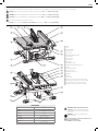 3
3
-
 4
4
-
 5
5
-
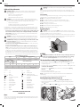 6
6
-
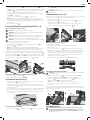 7
7
-
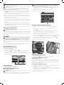 8
8
-
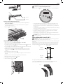 9
9
-
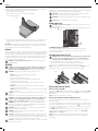 10
10
-
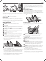 11
11
-
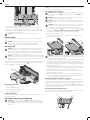 12
12
-
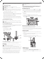 13
13
-
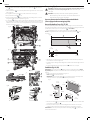 14
14
-
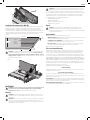 15
15
-
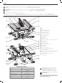 16
16
-
 17
17
-
 18
18
-
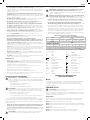 19
19
-
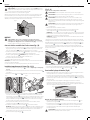 20
20
-
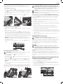 21
21
-
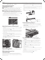 22
22
-
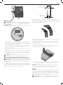 23
23
-
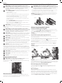 24
24
-
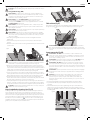 25
25
-
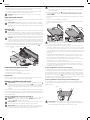 26
26
-
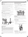 27
27
-
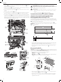 28
28
-
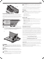 29
29
-
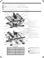 30
30
-
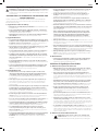 31
31
-
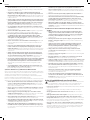 32
32
-
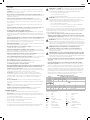 33
33
-
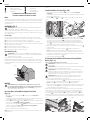 34
34
-
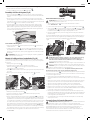 35
35
-
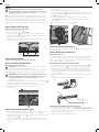 36
36
-
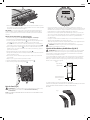 37
37
-
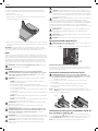 38
38
-
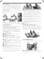 39
39
-
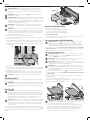 40
40
-
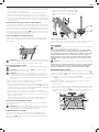 41
41
-
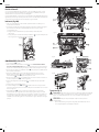 42
42
-
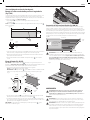 43
43
-
 44
44
-
 45
45
-
 46
46
-
 47
47
-
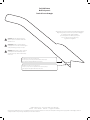 48
48


DeWalt DWE7491RS Manuel utilisateur
- Catégorie
- Outils électroportatifs
- Taper
- Manuel utilisateur
dans d''autres langues
- English: DeWalt DWE7491RS User manual
- español: DeWalt DWE7491RS Manual de usuario
Documents connexes
-
DeWalt DWE7491 Manuel utilisateur
-
DeWalt DWE7480 Manuel utilisateur
-
-
-
-
-
-
DeWalt DW744S TYPE 2 Le manuel du propriétaire
-
-
Autres documents
-
Delta 36-6013 Le manuel du propriétaire
-
Stanley SST1800 Manuel utilisateur
-
-
Milwaukee 2734-20-2736-20 Manuel utilisateur
-
Ryobi RTS10NST Le manuel du propriétaire
-
-
-
-
-
Laguna Tools F1 Fusion Le manuel du propriétaire