Axial AXI03006T1 Le manuel du propriétaire
- Catégorie
- Véhicules jouets
- Taper
- Le manuel du propriétaire
Ce manuel convient également à

INSTRUCTION MANUAL
BEDIENUNGSANLEITUNG
MANUEL D’UTILISATION
MANUALE DI ISTRUZIONI
AXI03006 T1/T2

2
EN
Age Recommendation: Not for children under 14 years. This is not a toy.
WARNING: Read the ENTIRE instruction manual to become familiar with the features of the product before operating. Failure to operate
the product correctly can result in damage to the product, personal property and cause serious injury.
This is a sophisticated hobby product. It must be operated with caution and common sense and requires some basic mechanical ability. Failure to
operate this Product in a safe and responsible manner could result in injury or damage to the product or other property. This product is not intended for
use by children without direct adult supervision. Do not use with incompatible components or alter this product in any way outside of the instructions
provided by Horizon Hobby, LLC. This manual contains instructions for safety, operation and maintenance. It is essential to read and follow all the
instructions and warnings in the manual, prior to assembly, setup or use, in order to operate correctly and avoid damage or serious injury.
NOTICE
All instructions, warranties and other collateral documents are subject to change at the sole discretion of Horizon Hobby, LLC. For up-to-date
product literature, visit horizonhobby.com or towerhobbies.com and click on the support or resources tab for this product.
MEANING OF SPECIAL LANGUAGE
The following terms are used throughout the product literature to indicate various levels of potential harm when operating this product:
WARNING: Procedures, which if not properly followed, create the probability of property damage, collateral damage, and serious injury OR
create a high probability of superfi cial injury.
CAUTION: Procedures, which if not properly followed, create the probability of physical property damage AND a possibility of serious injury.
NOTICE: Procedures, which if not properly followed, create a possibility of physical property damage AND a little or no possibility of injury.
As the user of this product, you are solely responsible for operating in a manner that does not endanger yourself and others or result in damage
to the product or property of others.
This model is controlled by a radio signal subject to interference from many sources outside your control. This interference can cause momentary
loss of control, so it is advisable to always keep a safe distance in all directions around your model as this margin will help avoid collisions or injury.
• Never operate your model with low transmitter batteries.
• Always operate your model in open spaces away from full-size
vehicles, traffi c and people.
• Never operate the model in the street or in populated areas for any
reason.
• Carefully follow the directions and warnings for this and any optional
support equipment (chargers, rechargeable battery packs, etc.) you use.
• Keep all chemicals, small parts and anything electrical out of the
reach of children.
• Never lick or place any portion of the model in your mouth as it could
cause serious injury or even death.
• Exercise caution when using tools and sharp instruments.
• Take care during maintenance as some parts may have sharp edges.
• Immediately after using your model, do NOT touch equipment
such as the motor, electronic speed control and battery, because
they generate high temperatures. You may burn yourself seriously
touching them.
• Do not put fi ngers or any objects inside rotating and moving parts, as
this may cause damage or serious injury.
• Always turn on your transmitter before you turn on the receiver in the
car. Always turn off the receiver before turning your transmitter off.
• Keep the wheels of the model off the ground when checking the
operation of the radio equipment.
SAFETY PRECAUTIONS AND WARNINGS
WARNING AGAINST COUNTERFEIT PRODUCTS: Always purchase from a Horizon Hobby, LLC authorized dealer to ensure
authentic high-quality Spektrum product. Horizon Hobby, LLC disclaims all support and warranty with regards, but not limited to,
compatibility and performance of counterfeit products or products claiming compatibility with DSM® or Spektrum technology.

3
EN
Your new Horizon Hobby vehicle has been designed and built with
a combination of waterproof and water-resistant components to
allow you to operate the product in many “wet conditions,” including
puddles, creeks, wet grass, snow and even rain.
While the entire vehicle is highly water-resistant, it is not completely
waterproof and your vehicle should NOT be treated like a submarine.
The various electronic components used in the vehicle, such as the
Electronic Speed Control (ESC), servo(s) and receiver are waterproof,
however, most of the mechanical components are water-resistant and
should not be submerged.
Metal parts, including the bearings, hinge pins, screws and nuts, as
well as the contacts in the electrical cables, will be susceptible to
corrosion if additional maintenance is not performed after running in
wet conditions. To maximize the long-term performance of your vehicle
and to keep the warranty intact, the procedures described in the “Wet
Conditions Maintenance” section below must be performed regularly
if you choose to run in wet conditions. If you are not willing to perform
the additional care and maintenance required, then you should not
operate the vehicle in those conditions.
CAUTION: Failure to exercise caution while using this
product and complying with the following precautions could
result in product malfunction and/or void the warranty.
GENERAL PRECAUTIONS
• Read through the wet conditions maintenance procedures and make
sure that you have all the tools you will need to properly maintain your
vehicle.
• Not all batteries can be used in wet conditions. Consult the battery
manufacturer before use. Caution should be taken when using Li-Po
batteries in wet conditions.
• Most transmitters are not water-resistant. Consult your transmitter’s
manual or the manufacturer before operation.
• Never operate your transmitter or vehicle where lightning may be present.
• Do not operate your vehicle where it could come in contact with salt
water (ocean water or water on salt-covered roads), contaminated
or polluted water. Salt water is very conductive and highly corrosive,
so use caution.
• Even minimal water contact can reduce the life of your motor if it
has not been certifi ed as water-resistant or waterproof. If the motor
becomes excessively wet, apply very light throttle until the water is
mostly removed from the motor. Running a wet motor at high speeds
may rapidly damage the motor.
• Driving in wet conditions can reduce the life of the motor. The
additional resistance of operating in water causes excess strain. Alter
the gear ratio by using a smaller pinion or larger spur gear. This will
increase torque (and motor life) when running in mud, deeper puddles,
or any wet conditions that will increase the load on the motor for an
extended period of time.
WET CONDITIONS MAINTENANCE
• Drain any water that has collected in the tires by spinning them at high
speed. With the body removed, place the vehicle upside down and pull
full throttle for a few short bursts until the water has been removed.
CAUTION: Always keep hands, fi ngers, tools and any loose
or hanging objects away from rotating parts when performing
the above drying technique.
• Remove the battery pack(s) and dry the contacts. If you have an air
compressor or a can of compressed air, blow out any water that may
be inside the recessed connector housing.
• Remove the tires/wheels from the vehicle and gently rinse the mud
and dirt off with a garden hose. Avoid rinsing the bearings and
transmission.
NOTICE: Never use a pressure washer to clean your vehicle.
• Use an air compressor or a can of compressed air to dry the vehicle
and help remove any water that may have gotten into small crevices or
corners.
• Spray the bearings, drive train, fasteners and other metal parts with
a water-displacing light oil. Do not spray the motor.
• Let the vehicle air dry before you store it. Water (and oil) may
continue to drip for a few hours.
• Increase the frequency of disassembly, inspection and lubrication of
the following:
- Front and rear axle hub assembly bearings.
- All transmission cases, gears and differentials.
- Motor—clean with an aerosol motor cleaner and re-oil the
bushings with lightweight motor oil.
WATER-RESISTANT VEHICLE WITH WATERPROOF ELECTRONICS
TABLE OF CONTENTS
Water-Resistant Vehicle With Waterproof Electronics ............................. 3
Box Contents.....................................................................................................4
Required Equipment ........................................................................................ 4
Recommended Tools ....................................................................................... 4
Getting Started Checklist ................................................................................ 5
Vehicle Parts ..................................................................................................... 5
Charge The Vehicle Battery ...........................................................................6
Install The Transmitter Batteries ...................................................................6
Transmitter Functions ......................................................................................6
Adjusting The Vehicle Battery Tray...............................................................7
Install The Vehicle Battery ............................................................................. 7
Binding ...............................................................................................................8
Range-Checking The Radio System .............................................................8
Using The Dig Transmission ...........................................................................8
Vehicle Maintenance ...................................................................................... 9
Spektrum Receiver/Esc Combo ................................................................... 10
Gear Ratios......................................................................................................10
Troubleshooting ..............................................................................................11
Limited Warranty ............................................................................................ 12
Warranty And Service Contact Information .............................................. 12
FCC Information .............................................................................................. 13
IC Information .................................................................................................13
Compliance Information For The European Union ................................... 13
Exploded Views ..............................................................................................50
Parts Lists ........................................................................................................ 57
Optional Parts .................................................................................................60
Electronics ...................................................................................................... 60
Notes ................................................................................................................60

4
EN
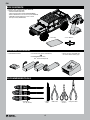
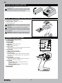
BOX CONTENTS
• Battery charger compatible with
the chosen vehicle battery type
• (4) AA Alkaline batteries
• Hex Drivers
(1.5, 2.0, 2.5mm)
• Hobby
Knife
• Side Cutter • Curved
Scissors
• Long-nose Plier
RECOMMENDED TOOLS
• Parts Bag • Cross Wrench
REQUIRED EQUIPMENT
• 2-3S Standard or “Shorty” LiPo Battery
OR
• 5-9 Cell NiMH/NiCd battery
(IC3
™
Connector Required)
• Spektrum
™
DX3
™
2.4GHz Transmitter (SPM2340)
• SCX10
™
III Jeep Gladiator RTR
- 35T Electric Motor (AX31312)
- Spektrum Receiver/ESC Combo (SPMXSE1040RX)
- Water Proof Metal Gear Surface Servo, 23T (SPMS614)
- SX107 Micro Analog Metal Gear Surface Servo
(For dig function) (SPMSSX107)

5
EN
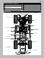
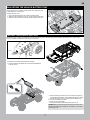
Steering Servo
Transmission
Driveshaft
Upper 4-link Bar
Differential
(inside axle housing)
Front Body Mount
Rear Body Mount
ESC Plug
Lower 4-link Bar
Shock Absorber
VEHICLE PARTS
GETTING STARTED CHECKLIST
Read the manual
Familiarize yourself with the vehicle and its components
Check all screws, especially the driveshaft setscrews, for
tightness from the factory
Charge the vehicle battery
Install 4 AA batteries in the transmitter
Power on the transmitter
Install the vehicle battery in the vehicle
Check for proper function of the throttle and steering
Range check the radio system
Drive the vehicle, challenge yourself and have FUN!
Perform any necessary vehicle maintenance
Steering Knuckle
“Shorty” Battery Tray
Standard Battery Tray
Receiver/Electronic
Speed Control (ESC)
Motor Cover

6
EN
INSTALL THE TRANSMITTER BATTERIES
TRANSMITTER FUNCTIONS
This transmitter requires 4 AA batteries.
1. Remove the battery cover from the transmitter.
2. Install the batteries as shown.
3. Install the battery cover.
CAUTION: NEVER remove the transmitter batteries while the
model is powered on. Loss of model control, damage, or injury
may occur.
CAUTION: If using rechargeable batteries, charge only
rechargeable batteries. Charging non-rechargeable batteries
may cause the batteries to burst, resulting in injury to persons and/or
damage to property.
CAUTION: Risk of explosion if battery is replaced by an incorrect
type. Dispose of used batteries according to national regulations.
Channel 3 Button (Dig Function)
Throttle/Brake
Steering Wheel
Steering Rate
Adjusts the end point of the steering
Brake Rate
Adjusts the braking end point.
Steering Trim
Adjusts the steering center point. Normally, the steering trim is
adjusted until the vehicle tracks straight.
Throttle Trim
Adjusts the throttle neutral point
SMART Battery Level Indicator
Servo Reversing
To reverse the Throttle (TH) or Steering (ST) channel, switch
the position of the correlating switch—“N” is for normal, “R”
is for reverse.
Throttle Limit
Limits throttle output to 50/75/100%
Select 50% or 75% for less experienced drivers or when you
are driving the vehicle in a small area.
Power LED
• Solid red lights: Indicates radio connectivity and
adequate battery power
• Flashing red lights: Indicates the battery voltage is
critically low. Replace batteries
Power Button
Bind Button
C
D
H
J
K
L
I
G
F
E
M
N
A/B
A/B.
C.
D.
E.
F.
G.
H.
I.
J.
K.
L.
M.
N.
Follow the manufacturer’s directions for your charger to properly
charge the vehicle battery.
CAUTION: Only use chargers designed to charge the chosen
battery type. Using an incorrect charger or incorrect charger
settings could cause the battery to catch fi re or explode.
CHARGE THE VEHICLE BATTERY
Channel 3 Button (Dig Function)

7
EN
Power
INSTALL THE VEHICLE BATTERY
2. Remove the four body clips from under the body.
3. Pull out slightly on the bottom sides of the body while lifting it
from the chassis.
4. Place the battery in the battery tray. The battery tray length may
be adjusted to fi t the battery as described in the previous section.
5. Secure the battery to the tray with the hook and loop strap.
6. Connect the battery to the ESC.
7. Power on the receiver/ESC.
8. Re-install the body and four body clips to the chassis.
NOTICE: Always power off the ESC and disconnect the battery
from the ESC before powering off the transmitter. Loss of vehicle
control may result.
1. Power on the transmitter.
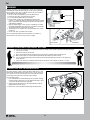
ADJUSTING THE VEHICLE BATTERY TRAY
The battery trays may be adjusted to fi t a wide range of battery sizes.
The rear battery tray is shown in the illustration. The side battery tray
is adjustable in the same manner.
To adjust the battery tray:
1. Loosen the four fl athead screws shown in the illustration.
2. Slide the ends of the battery tray in or out to fi t the desired battery.
3. Tighten the four fl athead screws. Do not over-tighten the screws.
The following steps show the installation of a standard size battery in the rear battery tray of the vehicle. If you wish to use a “shorty” style
battery, it should be installed in the side battery tray location.

8
EN
BINDING
The radio system should be checked before operating the vehicle to ensure proper operation and adequate range.
1. Turn on the transmitter.
2. Connect the battery in the vehicle.
3. Have a friend hold the vehicle while keeping hands and loose clothing away from moving parts.
4. Walk away until you are at the maximum planned operating distance from the vehicle.
5. Turn the steering wheel side to side and operate the throttle, both forward and reverse, checking for any
erratic behavior.
6. If any erratic behavior is exhibited, DO NOT operate the vehicle. Call customer service for assistance.
RANGE-CHECKING THE RADIO SYSTEM
The vehicle includes a “Dig” transmission which allows the rear axle
to lock while still allowing the front wheels to spin. Use this feature in
close quarters to turn the vehicle tighter than is possible with normal
4 wheel drive or to preload the suspension when needed.
To use the Dig function:
1. Press and hold the channel 3 B button on the transmitter. The Dig
function engages, locking the rear axle. Hold the B button as long
as you want the dig function to be engaged.
2. Advance the throttle and turn the steering wheel left or right to
tightly pivot the vehicle around.
3. Release the channel 3 B button to disengage the Dig function.
USING THE DIG TRANSMISSION
Binding is the process of programming the receiver to recognize the
GUID (Globally Unique Identifi er) code of a single specifi c transmitter.
The transmitter and receiver are bound at the factory. If you need to
rebind, follow the instructions below.
1. Connect a fully charged battery pack to the ESC/receiver.
2. Disconnect the “Dig” servo lead from the receiver.
3. Press and hold the bind button on the receiver.
4. Power ON the receiver. The red LED fl ashes, indicating the
receiver is in bind mode. Release the bind button after the red LED
begins to fl ash. The motor will make continuous descending tones
until binding is complete.
5. With the throttle trigger at neutral, press and hold the transmitter
bind button while powering on to put the transmitter in bind mode.
The throttle should be at neutral to set failsafe.
6. The bind process is complete when the green LED on the receiver
remains lit.
7. Connect the “Dig” servo lead to the receiver.
You must rebind when different failsafe positions are needed e.g.,
when throttle or steering reversing has been changed.
Bind Button
Bind ButtonPower Button
Power Switch

9
EN
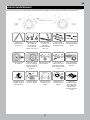
Replace any
noticeable bent or
broken parts
Check the wheel nuts
for tightness
If applicable, check
the slipper clutch for
proper operation
Check for wear on
the ball joints in
the steering and
suspension links
(replace if necessary)
Ensure the wheel
beads are still fi rmly
bonded around the
entire circumference
of the rim
Check the receiver
antenna for damage
Check driveshaft
set screws and
apply thread
locking compound if
necessary
Keep the chassis free
of dirt and debris
Check the steering
operation for any
binding
Inspect shock
absorbers for smooth
dampened operation
Check for loose
screws on the chassis,
especially the knuckle,
C-hub and axle lockout
screws
Inspect the spur
and pinion gears for
damage
Check for any loose
connections or frayed
wiring
Check the driveline
for smooth, bind free
operation
Replace the
transmitter batteries
when indicated by
the transmitter, as
described in the
Transmitter Functions
section
Just like a full size car or truck your RC vehicle must undergo periodic maintenance in order to ensure peak performance. Preventative maintenance
will also help avoid needless breakages which could result in costly repairs. Below are some suggestions to properly maintain your vehicle.
VEHICLE MAINTENANCE

10
EN
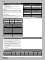
GEAR RATIOS
SPUR/PINION GEAR RATIO CHART - LCX TRANSMISSION
12 13 14 15 16 17 18
Low Speed (standard) 58.1 49.2 45.6 42.6 39.4 37.6 35.5
High Speed (optional) 39.8 36.5 31.3 29.2 27.3 25.7 24.3
SPEKTRUM RECEIVER/ESC COMBO
ESC AND TRANSMITTER CALIBRATION
OPERATION
1. Power on the transmitter.
2. Power on the receiver.
3. The green LED on the receiver will be illuminated when it is
connected to your transmitter.
4. Disconnect the battery from the ESC/Receiver after operation.
FAILSAFE
In the unlikely event that the radio link is lost during use, the 2-in-1 will
drive the throttle channel to the neutral (throttle off) position. If the 2-in-1 is
powered on prior to turning on the transmitter, it will enter failsafe mode,
leaving throttle off. When the transmitter is turned on, normal control will
resume.
LED INDICATORS
Upon powering ON the ESC, the red LED will blink and the motor will
emit a series of beeps to indicate its status.
The number of tones indicates (1) the ESC is in operation (2) the battery
mode detected and (3) the ESC is in a ready-to-use state.
FEATURE RED LED STATUS MOTOR SOUND
ESC Is In Operation
Rapid Blinking 4 Changing Tones
Ni-MH/Ni-CD Battery
2S Li-Po Battery
3S Li-Po Battery
1 Blink
2 Blinks
3 Blinks
1 Short Tone
2 Short Beeps
3 Short Beeps
ESC Ready,
No Transmitter Signal
2 Short Blinks,
Red Blink Repeating
2 Ascending Tones,
Descending Tones Repeating
OPERATION LED STATUS
Forward
Partial Throttle Green Solid, Red Blinks
Full Throttle Green and Red Solid
Reverse
Partial Throttle Green Solid, Red Blinks
Full Throttle Green and Red Solid
Brake
Partial Green Solid, Red Blinks
Full Green and Red Solid
Stop Green Solid
Battery Low Voltage or No Signal Red Blinks
Overheat Green Blinks
Over Current Protection Green and Red Triple Blinks
The included transmitter and ESC/receiver combo automatically
calibrate when powered on. Follow the procedure below to ensure
accurate calibration between the transmitter and ESC/receiver.
1. Connect a fully charged battery to the ESC/receiver. Ensure the
power switch is in the OFF position.
2. Power the transmitter ON. Ensure the throttle is not reversed, the
throttle trim is neutral and the throttle travel range is at 100%.
3. With the throttle at neutral, power ON the ESC/receiver.
4. Leave the throttle trigger and trims at neutral for at least 3
seconds.The ESC/Receiver automatically calibrates the throttle
range after 3 seconds.
5. The LED will blink and the motor will beep to indicate the battery
mode selection.
6. One long LED blink and one long beep indicates the ESC is ready to run.
SPECIFICATIONS
Type
Waterproof DSMR ESC/Receiver
2-in-1 with SMART Telemetry
Dimensions (L × W × H) 54mm × 33.5mm × 20.5mm
Antenna Length 31mm
Channels 4 (No Throttle Servo Output)
Weight 68g
Band 2404 MHz – 2476 MHz
Servo Output Voltage
6V up to 3A, Shared with Auxillary Light
Connectors
Telemetry Features
Battery Voltage, Current, ESC Temp,
Battery Data (with SMART Battery)
Battery Input Connector IC3
™
(EC3
™
Compatible)
Voltage Range 2–3S Li-Po*/5–9S NiMH
Max Current 40A Continuous/ 180A Burst
Motor Connectors 3.5mm Bullet
* Default setting for low voltage cutoff is Li-Po. Optional Dynamite
Program Card (DYNS3005) required to change the Battery Type Setting.

11
EN
TROUBLESHOOTING
PROBLEM POSSIBLE CAUSE SOLUTION
The system will not connect
Your transmitter and receiver are too
close together
Move transmitter 8 to 12 feet away from receiver
You are near metal objects Move to an area with less metal
The receiver is bound to a different
model memory
Make sure the correct model memory is active in your
transmitter
Your transmitter was placed into bind
mode and is no longer bound to your
receiver
Rebind your transmitter and receiver, and then re-calibrate
The receiver goes into failsafe a short
distance away from the transmitter
Check for damage on the receiver
antenna
Make sure your receiver antenna is protected and located
as high as practical
Replace the receiver or contact Horizon Product Support
The receiver stops responding during
operation
Low receiver battery voltage. If the
battery voltage is low, it may drop
below 3.5V momentarily, causing the
receiver to brown-out, then reconnect
Charge the receiver or vehicle battery. Spektrum receivers
require at least 3.5V to operate
Loose or damaged wires or connectors
between battery and receiver
Check the wires and connection between the battery and
receiver. Repair or replace wires and/or connectors
Vehicle does not move
Batteries are not installed properly in
the transmitter
Ensure the transmitter batteries are properly installed
Weak or no battery in the vehicle Install a freshly charged vehicle battery
Damaged motor Replace the motor
Frayed or broken wiring Replace any damaged wiring
ESC is shut down by heat protection circuit
Allow the ESC to cool down completely
Loss of vehicle control
Improper antenna placement
Ensure the transmitter antenna is not blocked and the
receiver antenna is located properly
Weak or no batteries in the transmitter
or vehicle
Install a freshly charged vehicle battery and new
transmitter batteries
Neutral or trim position is incorrect Adjust the steering trim
Receiver and/or battery not connected
properly
Check all receiver and battery connections
Steering and/or throttle function is
reversed
Servo travel is reversed at the transmitter Set the transmitter servo reversing switch to the correct position
Motor wires are not connected properly Check all motor wires for correct polarity and secure connection
ESC ON - No motor function, audible tone
or LED
Battery/connection issue Recharge/replace battery. Secure all connections
Damaged ESC/switch Repair/replace ESC switch/ESC
Damaged motor Repair/replace
Motor- Stops and LED blinks
Low voltage protection When the ESC LED blinks, recharge/replace battery
Overheat protection
When the LED blinks, let motor/ESC cool, change set up or
gearing to avoid overheating
Motor- Accelerates irregularly
Battery issue Repair damaged wiring/replace battery
Incorrect gearing Adjust/replace gearing
Worn or damaged motor Repair/replace motor
Motor- Does not turn continuously in
response to throttle
ESC/motor damaged Repair/replace wiring or motor/ESC
Motor- Slows but will not stop Incorrect transmitter/ESC calibration
Adjust throttle travel/other throttle settings on the
transmitter/ESC. Repeat the ESC Calibration Procedure
Steering servo- Operates; motor does not
run
Damaged motor
Test the motor apart from the vehicle system, repair/replace
motor as needed
Incorrect transmitter/ESC calibration
Adjust throttle travel/other throttle settings on the
transmitter/ESC. Repeat the ESC Calibration Procedure
Steering/motor- not functioning
Low battery voltage Recharge/replace
Wrong model memory selected on
transmitter
Select correct model settings on your transmitter, refer to
transmitter and/or receiver manual
Receiver not bound to transmitter
Bind transmitter to receiver, refer to transmitter and/or
receiver manual
Vehicle- Does not operate at full speed
Battery issue Recharge/replace
Incorrect transmitter/ESC calibration
Adjust throttle travel/other throttle settings on the
transmitter/ESC. Repeat the ESC Calibration Procedure

12
EN
What this Warranty Covers
Horizon Hobby, LLC, (Horizon) warrants to the original purchaser that the
product purchased (the “Product”) will be free from defects in materials
and workmanship for a period of 2 years from the date of purchase.
What is Not Covered
This warranty is not transferable and does not cover (i) cosmetic damage,
(ii) damage due to acts of God, accident, misuse, abuse, negligence,
commercial use, or due to improper use, installation, operation or
maintenance, (iii) modifi cation of or to any part of the Product, (iv)
attempted service by anyone other than a Horizon Hobby authorized
service center, (v) Product not purchased from an authorized Horizon
dealer, or (vi) Product not compliant with applicable technical regulations
or (vii) use that violates any applicable laws, rules, or regulations.
OTHER THAN THE EXPRESS WARRANTY ABOVE, HORIZON MAKES NO
OTHER WARRANTY OR REPRESENTATION, AND HEREBY DISCLAIMS
ANY AND ALL IMPLIED WARRANTIES, INCLUDING, WITHOUT
LIMITATION, THE IMPLIED WARRANTIES OF NON-INFRINGEMENT,
MERCHANTABILITY AND FITNESS FOR A PARTICULAR PURPOSE. THE
PURCHASER ACKNOWLEDGES THAT THEY ALONE HAVE DETERMINED
THAT THE PRODUCT WILL SUITABLY MEET THE REQUIREMENTS OF
THE PURCHASER’S INTENDED USE.
Purchaser’s Remedy
Horizon’s sole obligation and purchaser’s sole and exclusive remedy
shall be that Horizon will, at its option, either (i) service, or (ii) replace,
any Product determined by Horizon to be defective. Horizon reserves
the right to inspect any and all Product(s) involved in a warranty
claim. Service or replacement decisions are at the sole discretion of
Horizon. Proof of purchase is required for all warranty claims. SERVICE
OR REPLACEMENT AS PROVIDED UNDER THIS WARRANTY IS THE
PURCHASER’S SOLE AND EXCLUSIVE REMEDY.
Limitation of Liability
HORIZON SHALL NOT BE LIABLE FOR SPECIAL, INDIRECT,
INCIDENTAL OR CONSEQUENTIAL DAMAGES, LOSS OF PROFITS OR
PRODUCTION OR COMMERCIAL LOSS IN ANY WAY, REGARDLESS OF
WHETHER SUCH CLAIM IS BASED IN CONTRACT, WARRANTY, TORT,
NEGLIGENCE, STRICT LIABILITY OR ANY OTHER THEORY OF LIABILITY,
EVEN IF HORIZON HAS BEEN ADVISED OF THE POSSIBILITY OF SUCH
DAMAGES. Further, in no event shall the liability of Horizon exceed the
individual price of the Product on which liability is asserted. As Horizon
has no control over use, setup, fi nal assembly, modifi cation or misuse,
no liability shall be assumed nor accepted for any resulting damage
or injury. By the act of use, setup or assembly, the user accepts all
resulting liability. If you as the purchaser or user are not prepared to
accept the liability associated with the use of the Product, purchaser
is advised to return the Product immediately in new and unused
condition to the place of purchase.
Law
These terms are governed by Illinois law (without regard to confl ict of law
principals). This warranty gives you specifi c legal rights, and you may also
have other rights which vary from state to state. Horizon reserves the right
to change or modify this warranty at any time without notice.
WARRANTY SERVICES
Questions, Assistance, and Services
Your local hobby store and/or place of purchase cannot provide
warranty support or service. Once assembly, setup or use of the Product
has been started, you must contact your local distributor or Horizon
directly. This will enable Horizon to better answer your questions and
service you in the event that you may need any assistance. For questions
or assistance, please visit our website at www.horizonhobby.com,
submit a Product Support Inquiry, or call the toll free telephone number
referenced in the Warranty and Service Contact Information section to
speak with a Product Support representative.
Inspection or Services
If this Product needs to be inspected or serviced and is compliant in
the country you live and use the Product in, please use the Horizon
Online Service Request submission process found on our website
or call Horizon to obtain a Return Merchandise Authorization (RMA)
number. Pack the Product securely using a shipping carton. Please
note that original boxes may be included, but are not designed to
withstand the rigors of shipping without additional protection. Ship
via a carrier that provides tracking and insurance for lost or damaged
parcels, as Horizon is not responsible for merchandise until it arrives
and is accepted at our facility. An Online Service Request is available
at http://www.horizonhobby.com/content/service-center_render-
service-center. If you do not have internet access, please contact
Horizon Product Support to obtain a RMA number along with
instructions for submitting your product for service. When calling
Horizon, you will be asked to provide your complete name, street
address, email address and phone number where you can be reached
during business hours. When sending product into Horizon, please
include your RMA number, a list of the included items, and a brief
summary of the problem. A copy of your original sales receipt must be
included for warranty consideration. Be sure your name, address, and
RMA number are clearly written on the outside of the shipping carton.
NOTICE: Do not ship Li-Po batteries to Horizon. If you have any
issue with a Li-Po battery, please contact the appropriate Horizon
Product Support offi ce.
Warranty Requirements
For Warranty consideration, you must include your original sales
receipt verifying the proof-of-purchase date. Provided warranty
conditions have been met, your Product will be serviced or replaced
free of charge. Service or replacement decisions are at the sole
discretion of Horizon.
Non-Warranty Service
Should your service not be covered by warranty, service will be
completed and payment will be required without notifi cation or
estimate of the expense unless the expense exceeds 50% of the retail
purchase cost. By submitting the item for service you are agreeing
to payment of the service without notifi cation. Service estimates
are available upon request. You must include this request with your
item submitted for service. Non-warranty service estimates will be
billed a minimum of 1/2 hour of labor. In addition you will be billed for
return freight. Horizon accepts money orders and cashier’s checks,
as well as Visa, MasterCard, American Express, and Discover cards.
By submitting any item to Horizon for service, you are agreeing to
Horizon’s Terms and Conditions found on our website http://www.
horizonhobby.com/content/service-center_render-service-center.
ATTENTION: Horizon service is limited to Product compliant in
the country of use and ownership. If received, a non-compliant
Product will not be serviced. Further, the sender will be responsible
for arranging return shipment of the un-serviced Product, through
a carrier of the sender’s choice and at the sender’s expense.
Horizon will hold non-compliant Product for a period of 60 days from
notifi cation, after which it will be discarded.
10/15
COUNTRY OF PURCHASE HORIZON HOBBY CONTACT INFORMATION ADDRESS
United States of America
Horizon Service Center
(Repairs and Repair Requests)
servicecenter.horizonhobby.com/RequestForm/
2904 Research Rd
Champaign, IL 61822
Horizon Product Support
(Product Technical Assistance)
productsupport@horizonhobby.com
877-504-0233
Sales
websales@horizonhobby.com
800-338-4639
European Union
Horizon Technischer Service service@horizonhobby.eu
Hanskampring 9
D 22885 Barsbüttel, Germany
Sales: Horizon Hobby GmbH +49 (0) 4121 2655 100
LIMITED WARRANTY
WARRANTY AND SERVICE CONTACT INFORMATION

13
EN
INSTRUCTIONS FOR DISPOSAL OF WEEE BY USERS IN THE EUROPEAN UNION
This product must not be disposed of with other waste. Instead, it is the user’s responsibility to dispose of their waste equipment by
handing it over to a designated collections point for the recycling of waste electrical and electronic equipment. The separate collection
and recycling of your waste equipment at the time of disposal will help to conserve natural resources and ensure that it is recycled in a
manner that protects human health and the environment. For more information about where you can drop off your waste equipment for
recycling, please contact your local city offi ce, your household waste disposal service or where you purchased the product.
EU COMPLIANCE STATEMENT:
Axial SCX10 III Jeep Gladiator (AXI03006)
Horizon Hobby, LLC hereby declares that this product is in compliance with the essential requirements and other relevant provisions of
the RED Directive.
A copy of the EU Declaration of Conformity is available online at: http://www.horizonhobby.com/content/support-render-compliance.
Frequency Range: 2404-2478MHz
Max EIRP: 19.9dBm
FCC INFORMATION
IC INFORMATION
COMPLIANCE INFORMATION FOR THE EUROPEAN UNION
CAN ICES-3 (B)/NMB-3(B)
Contains IC: 6157A-KATY1T
This device complies with ISED Canada licence-exempt RSS standard(s). Operation is subject to the following two conditions: (1) this device may not cause
interference, and (2) this device must accept any interference, including interference that may cause undesired operation of the device.
Contains FCC ID: BRWKATY1T
SUPPLIER’S DECLARATION OF CONFORMITY
Axial SCX10 III Jeep Gladiator (AXI03006)
This device complies with part 15 of the FCC Rules. Operation is subject to the following two conditions: (1) This device may not cause harmful
interference, and (2) this device must accept any interference received, including interference that may cause undesired operation.
CAUTION: changes or modifi cations not expressly approved by the party responsible for compliance could void the user’s authority to
operate the equipment.
NOTE: This equipment has been tested and found to comply with the limits for a Class B digital device, pursuant to part 15 of the FCC Rules.
These limits are designed to provide reasonable protection against harmful interference in a residential installation. This equipment generates,
uses and can radiate radio frequency energy and, if not installed and used in accordance with the instructions, may cause harmful interference
to radio communications. However, there is no guarantee that interference will not occur in a particular installation. If this equipment does cause
harmful interference to radio or television reception, which can be determined by turning the equipment off and on, the user is encouraged to try
to correct the interference by one or more of the following measures:
• Reorient or relocate the receiving antenna.
• Increase the separation between the equipment and receiver.
• Connect the equipment into an outlet on a circuit different from that to which the receiver is connected.
• Consult the dealer or an experienced radio/TV technician for help.
Horizon Hobby, LLC
2904 Research Rd.,
Champaign, IL 61822
Email: compliance@horizonhobby.com
Web: HorizonHobby.com

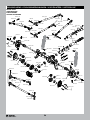
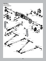
50
EXPLODED VIEWS // EXPLOSIONSZEICHNUNGEN // VUES ÉCLATÉES // VISTE ESPLOSE
AXI234006
AXI234004
AXI232017
AXI234012
AXI234006
AXI234006
AXI234003
AXI235109
AXI234004
AXI234004
AXI234004
AXI234010
AXA120
AXI234013
AXI234004
AXA1230
AX31403
AX31403
AX34106
AX31066
AXI232003
AXI234004
AXA1221
AXI232017
AXA0286
AX31148
AXI235016
AXI234003
AXA144
AXA144
AXI235014
AX31028
AXA1221
AXI232006
AXI232027
AXI234008
AXA1221
AXI232008
AXI235110
AXI237009
AXA120
AXI234004
AXI234004
AXI234004
AXI234006
AXI234006
AXI234006
AXI232018
AX30165
AXI235014
AXA1221
AXI234011
AXI235109
AX31148
AXA120
AX31028
AXI232017
AXI234004
AXI234004
AXI232008
AX30165
AX31043
AX31043
AXI234004
AXA1221
AXI232027
AXA1221
AXI237009
AXI232018
AXI237008
AXI232002
AX31047
AX31406
AXI232002
AXI232026
AXI232006
AXA1230
AXA1221
AXI234006
AXI234006
AXI234013
FRONT AXLE
VORDERACHSE
ESSIEU AVANT
ASSALE ANTERIORE

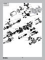
51
REAR AXLE
HINTERACHSE
ESSIEU ARRIÈRE
ASSALE POSTERIORE
AXI235014
AXI232018
AXI232023
AXA1221
AXA1221
AXA1221
AXA120
AXA120
AXI237009
AXI234006
AXI234006
AXI232028
AXI232008
AX31065
AXA1221
AXI234006
AXI234003
AXI232018
AXI232023
AX31065
AXI232008
AXI235014
AX31074
AXI232003
AXI232028
AXI232007
AXI232002
AXI232026
AX31006
AX31406
AX31406
AXI237009
AXI234004
AXI234004
AXI234004
AXI234004
AXI232038
AXI235016
AXA1221
AXA0286
AX31028
AXA144
AXA144
AX31028
AXA0286
AX31148
AXI232038
AXI232038
AXI234019
AX31148
AXI234019
AXI234018
AXI234018
AXI234004
AXI234004
AXI234004
AXI232007
AXI234004
AXI234003
AXI234006
AXI234006
AXA120

52
AXA149
AXA146
AXA1392
AX31403
AXI232036
AXI232029
AXA1221
AXI232037
AXI232029
AXI235178
AXI235178
AXI232030
AX30569
AXI232029
AXA0109
AX31185
AXA144
AXA150
AXI232034
AXI232015
AXI232029
AXI232035
AXI232029
AXI232036
AXI232036
AXI232035
AXI232035
AXI236173
AXI232033
AXI232031
AXI232031
AXI232029
AXI235178
AXI232036
AXI232035
AXI232037
AXI232035
AXA149
AXI232033
AXI232031
AX31312
AXA1391
AXI232031
AXA1221
AXA1392
AXI235102
AXA1221
AXA1221
AXA1221
AXA1221
AXA1391
AXA1391
AXI235178
AX31250
AXI232015
AXI232029
AXA1221
AXA140
AXA1221
AXA1221
AXA291
AXI232035
AXI232032
AXA1218
AXA1218
AXI237007
AXA1243
AXI232032
AXI232035
AXA0109
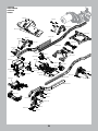
TRANSMISSION
GETRIEBE
TRANSMISSION
TRASMISSIONE

53
AXA119
AXI231017
AXI231017
AXA146
AXI231024
AXI231017
AXA119
AXA146
AXA118
AXA146
AXA144
AXI235109
AXI231017
AXI231016
AXA146
AX31185
AXI231015
AXI231022
AXA115
AXI231014
TACM0245
AXI231021
AXI231022
AXA114
AXA146
AXI235109
AXA118
AXA118
AXI231009
AXA114
AXI231011
AXI231011
AXI231016
AX31185
AXA146
AXA144
AXA149
AXI231008
AX31185
AXI231012
AXA114
AXA118
AXA115
AXA115
AXI231009
AXI231009
AXA0109
AXA115
AXI231010
AXI231016
AXI231015
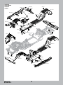
CHASSIS
KAROSSERIE
CHÂSSIS
TELAIO

54
AXI231019
AXI231018
AXA013
AXA0109
AXA144
AXA116
AXI231014
AXA013
AXA114
AXA114
AXI230030
AXI235167
AXA0286
AXA116
AXI231023
AXI231008
SPMSSX107
AXI235169
AXI232036
AXI230018
AXI231023
AXI230030
AXA0286
AXA114
AXA114
AXA0109
AXA0109
AXA116
AXA114
AXA013
AXI231019
AXA144
SPMXSE1040RX
AXI231020
CHASSIS
KAROSSERIE
CHÂSSIS
TELAIO

55
AXI230022
AXI235097
AXI230022
AXI235167
AXI230020
AXI230020
AXA013
AXA013
AXI235167
AXI230022
AXI233003
AXI230022
AXI31374
AXI235167
AXI230022
AXI230020
AXI235178
AXA114
AXA114
AXI230029
AXI235014
AXI230029
AXI235231
AXI230027
AXI230027
AXI230028
AXI230028
AXI230026
AXI230027
AXI230026
AXI230027
AXI235231
AXI230028
AXI230028
AXI230027
AXI230027
AXI235014
AXI231024
AXI230022
AX31374
AX31374
AXI233003
AX31374
AX31374
AXI233003
AXI230022
AXI230022
AXI230020
AXI223167
AXI223167
AXI223167
AXI235169
AXI235169
AXI235169
AXI235169
AXI235169
AXI235169
AXI235169
AXI235169
AXI233003
AXI233020
AXI235167
AXI233022
AXI235168
AXI235168
AXI235168
AXI235168
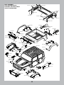
BODY ASSEMBLY
KAROSSERIEMONTAGE
ENSEMBLE DE CARROSSERIE
GRUPPO CARROZZERIA

56
AXI233002
AXI233003
AXI233012
AX1392
AXI233002
AXI233002
AXI25099
AXI233011
AXI233002
AXI233017 - Rear
AXI233015 - Front
AXI233003
AXI235094
AXI233002
AXA1059
AXI43009
AXI43010
AX31250
AXI43009
AXI43009
AXA232018
AXA115
AXI236172
AXA1059
AXA1059
AXA1059
SHOCK ABSORBERS
STOSSDÄMPFER
AMORTISSEURS
AMMORTIZZATORI
WHEELS AND TIRES
REIFEN UND RÄDER
ROUES ET PNEUS
RUOTE E PNEUMATICI
La page est en cours de chargement...
La page est en cours de chargement...
La page est en cours de chargement...
La page est en cours de chargement...
La page est en cours de chargement...
-
 1
1
-
 2
2
-
 3
3
-
 4
4
-
 5
5
-
 6
6
-
 7
7
-
 8
8
-
 9
9
-
 10
10
-
 11
11
-
 12
12
-
 13
13
-
 14
14
-
 15
15
-
 16
16
-
 17
17
-
 18
18
-
 19
19
-
 20
20
-
 21
21
-
 22
22
-
 23
23
-
 24
24
-
 25
25


Axial AXI03006T1 Le manuel du propriétaire
- Catégorie
- Véhicules jouets
- Taper
- Le manuel du propriétaire
- Ce manuel convient également à
dans d''autres langues
- English: Axial AXI03006T1 Owner's manual
Documents connexes
-
Horizon Hobby Axial SCX-10 III JEEP JLU WRANGLER Le manuel du propriétaire
-
Axial AXI90074T1 Le manuel du propriétaire
-
-
-
-
-
Axial AXI03005T2 Le manuel du propriétaire
-
Team Losi Racing AXI03019 Le manuel du propriétaire
-
-
Autres documents
-
Losi LOS05021T1 Le manuel du propriétaire
-
Losi LOS03019T1 Le manuel du propriétaire
-
-
-
Arrma ARA5810 Le manuel du propriétaire
-
Dynamite DYNS0900 Le manuel du propriétaire
-
Monoprice 34827 Manuel utilisateur
-
 Crem Coffee Unity Instruction Sheet
