
Documentazione
Tecnica
M02
rev. 2.2
12/2002
©
CAME
CANCELLI
AUTOMATICI
119GM02
SERIE GARD |
GARD SERIES
|
SÉRIE GARD |
BAUREIHE GARD
|
SERIE GARD
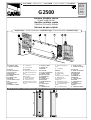
G2500
CANCELLI AUTOMATICI
Barriera stradale veloce
Rapid road barrier
Barrière routière rapide
Straßen-Schnellschranke
Barrera de paso rápido
Impianto tipo -
Standard installation -
Installation type
- Standard Montage -
Instalaciòn tipo
2x1 mm
2
3x1 mm
2
230V 3x1.5 mm
2
4x1
TXTX
TXTX
TX
RXRX
RXRX
RX
2x1.5
mm
2
1 - Groupe G 2500
2 - Armoire de
commande
Accessoires
3 - Lisse en aluminium
4 - Bandes rouges
phosphorescentes
5 - Clignotant de
mouvement
6 - Colonne pour
photocellules
7 - Photocellules de
sécurité
8 - Colonne pour
sélecteur
9 - Sélecteur à clé
1 - Antriebsaggregat G
2500
2 - Schalttafel
Zubehör
3 - Aluminium-
Schrankenbaum
4 - Rote
Phosphoreszenz-Streifen
5 - Blinkleuchte
“Schrankenbaum in
Bewegung”
6 - Photozellen-Säule
7 - Sicherheitsphotozellen
8 - Schlüsselschalter-
Säule
9 - Schlüsselschalter
1 - Grupo G 2500
2 - Cuadro de mando
Accesorios
3 - Barra de aluminio
4-Bandas rojas
fosforescentes
5 - Lámpara
intermitente de
movimiento
6 - Columna para
fotocélula
7 - Fotecélulas de
seguridad
8 - Columna para
selector
9 - Selector de llave
1 - Gruppo G 2500
2 - Quadro comando
Accessori
3 - Asta in alluminio
4 - Strisce rosse
fosforescenti
5 - Lampeggiatore di
movimento
6 - Colonnina per
fotocellule
7 - Fotocellule di sicu-
rezza
8 - Colonnina per
selettore
9 - Selettore a chiave
1 - G 2500 unit
2 - Control panel
Accessories
3 - Aluminium barrier rod
4 - Red phosphorescent
strips
5 - Flashing movement
warning light
6 - Photocell column
7 - Safety photocells
8 - Column for key-
operated selector switch
9 - Key-operated selector
switch
1007
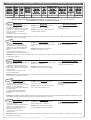
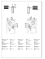
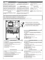
Misure di ingombro - External dimensions - Mesures d'encombrement - Außenabmessungen - Dimensiones máximas

2
Dati relativi ai valori di alimentazione nominale. -
These technical specifications apply when unit is powered at nominal voltage.
Données relatives aux valeurs d'alimentation nominale. -
Die Daten beziehen sich auf die Nennanschlußwerte.
Datos relativos a los valores de alimentación nominal.
Motoriduttore
Ge ar motor
Motoréducteur
Getriebemotor
Mot orr educ tor
Versione
Version
Version
Version
Versión
Peso
Weight
Poi ds
Gew.
Peso
Alimentazione
Power supply
Alimentation
Stromversorg.
Alimentación
Corrente nominale
Current draw
Courant nominal
Nennstrom
Corriente nominal
Potenza
Power
Puissance
Leistung
Potencia
Intermittenza lavoro
Duty cycle
Intermittence travail
Einschaltdauer
Interm.trabajo
Rapporto di riduz.
Final gear ratio
Rapport de réduct.
Untersetzung
Relación de reduc.
Coppia
Torque
Couple
Drehmoment
Par
Tempo apert.
Ope ni ng ti me
Te mps o uv er t .
Öffnungszeit
Tiempo apert.
101GARD25 1.1 39.5Kg 230V 1A 120W 30% 1/202 i 70Nm 2sec.
Caratteristiche tecniche - Technical features - Caractéristiques technique - Technische Daten - Descripción técnica
Accessori:
G 0251 Asta in alluminio verniciato bianco
sezione 60x40 mm, L = 2700 mm.
G 0257 Snodo per asta G 0251 (lunghezza
massima dell'asta 2 metri).
Descrizione:
- Barriera automatica per passaggi con
luce netta fino a 2.5 m.
- Progettata e costruita interamente dalla
CAME S.p.A., rispondente alle vigenti
norme di sicurezza, con grado di
protezione IP 54.
- Garantita 24 mesi salvo manomissioni.
Accessori opzionali:
G 0461 Striscie rosse fosforescenti per
aste
(confezione 24 pezzi).
Attenzione! Controllate che le apparecchiature di comando, di sicurezza e gli accessori siano originali CAME; ciò garantisce e rende l'impianto
di facile esecuzione e manutenzione.
Accessories:
G 0251 Cross-section 60x40 mm, L = 2700
mm aluminium barrier rod with white enamel
finish.
G 0257 Articulated joint for G 0251 bar
(maximum bar length: 2 metres).
Description:
- Automatic barrier for controlling
passages up to 2.5 meters wide.
- Designed and constructed entirely by
CAME S.p.A. in compliance with safety
standards and with IP 54 protecting
rating.
- Guaranteed for 24 months, unless
tampered with by unauthorized personnel.
Optional accessories:
G 0461 Red phosphorescent strips for
barrier rods (package of 24).
Important! Check that all control and safety systems and accessories are original CAME products; this will ensure that the system is simple
to install and to maintain.
Accessoires:
G 0251 Lisse en aluminium verni blanc section
60x40 mm, L = 2700 mm.
G 0257 Articulation pour lisse G 0251
(longueur maximum de la lisse 2 mètres).
Description:
- Barrière automatique pour passages net
allant jusqu'à 2.5 m.
- Entièrement conçue et réalisée par
CAME S.p.A, conformément aux normes
de sécurité en vigueur et avec degré de
protection IP 54.
- Garantie 24 mois, sauf en cas de
mauvaise manipulation.
Accessoires en option:
G 0461 Bandes rouges phosphorescentes
pour lisse (kit de 24 pièces).
Zubehör:
G 0251 Aluminium-Stange, weiß lackiert,
Schnitt 60x40 mm, L = 2700 mm.
G 0257 Gelenk für Schrankenbaum G 0251
(max. Länge Schrankenbaum 2 m).
Beschreibung:
- Automatische Schranke für lichte
Durchfahrtsbreiten von bis zu 2,5 m.
- Vollkommen von der CAME S.p.A. den
geltenden Sicherheitsnormen.
entsprechend entwickelt und hergestellt.
Schutzgrad IP 54.
- 24 Monate Garantie, vorbehaltlich
unsachgemäßer Handhabung und
Montage.
Zubehör auf Anfrage:
G 0461Rote Phosphoreszenz-Streifen
für Schrankenbäume (24-Stück-
Packung).
Attention! Vérifiez que l'appareillage de commande, de sécurité et les accessoires sont des produits originaux CAME afin de garantir l'installation
et d'en faciliter le montage et l'entretien.
Achtung! Wir empfehlen, original CAME-Steuergeräte und Sicherheitsvorrichtungen mit dem entsprechenden Zubehör zu installieren, um eine
einwandfreie Montage und problemlose Wartung der Anlage gewährleisten zu können.
Accesorios:
G 0251 Barra de aluminio pintado blanco
sección 60x40 mm, L = 2700 mm.
G 0257 Articulación para barrera G 0251
(longitud máxima de la barrera 2 metros).
Descripción:
- Barrera autómatica para pasos con luz
neta de hasta 2,5 m.
- Diseñada y fabricada enteramente por
CAME S.p.A., cumpliendo con las
normas de seguridad vigentes, con
grado de protección IP 54.
- Garantizado 24 meses salvo
manipulaciones.
Accesorios opcionales:
G 0461 Bandas rojas fosforescentes para
barras (paquete de 24 piezas).
Atención! Comprobar que los equipos de mando, de seguridad y los accesorios sean originales CAME; lo cual garantiza y facilita el uso y el
mantenimiento del aparato.
FRANÇAIS
ITALIANO
ENGLISH
DEUTSCH
ESPAÑOL

3
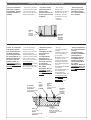
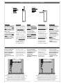
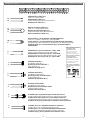
Montaggio - Installation - Montage - Montage - Montaje
- Girar la llave del
lado puerta y quitar
esta última. Quitar
los cuatro tornillos y
las arandelas.
- Den an der
Revisionstür
befindlichen Schlüssel
drehen und die Tür
entfernen. Die vier
Schrauben und die
Scheiben
entfernen.
- Girare la chiave del
lato porta e togliere
quest'ultima. Togliere
i quattro bulloni e le
rondelle.
- Turn the key located
on the door side of the
unit and remove the
door. Remove the four
bolts and washers.
- Tourner la clé du
côté de la porte et
enlever cette
dernière. Enlever les
quatre boulons et les
rondelles.
Bullone
Bolt
Boulon
Mutterschraube
Tornillo
Rondella
Washer
Rondelle
Scheibe
Arandela
- Unire la controbase
e le quattro zanche
(con relativi bulloni e
rondelle in dotazio-
ne). Annegare il tutto
in una piazzola di ce-
mento predisponen-
do l'arrivo dei cavi
elettrici. NOTA: la
controbase dovrà ri-
sultare
perfettamente
in bolla.
- Join the mounting
base and the four
anchor stays (use the
bolts and washers
provided with the unit),
and sink the assembly
into a cement base.
NOTE: be sure that the
mounting base is
perfectly level, and that
the electrical cables for
the unit protrude in the
area indicated.
- Monter les quatre
agrafes à la
contrebase (à l'aide
des boulons et
rondelles
correspondants,
fournis avec le
matériel). Plonger le
tout dans une base
en ciment en
prévoyant l'arrivée
des câbles
électriques. N.B: la
contrebase devra
être
parfaitement de
niveau.
- Die vier
Verankerungsbügel
(mit den
entsprechenden und
zum Lieferumfang
gehörenden
Mutterschrauben und
Scheiben) an der
Verankerungsplatte
befestigen und dann
diese Montageeinheit
in eine
Betonfundamentplatte
versenken.
Den Kabelausgang für
die elektrischen
Anschlußkabel
vorbereiten. ANM.: die
Verankerungsplatte
muß perfekt
waagerecht
ausgerichtet sein.
- Unir la contrabase a
las cuatro armaduras
(con los
correspondientes
tornillos y arandelas
suministrados).
Sumergirlo todo en
una plataforma de
cemento predispo-
nendo la llegada de
los cables
elécrtricos. NOTA: la
contrabase tiene que
estar perfectamente
nivelada.
Controbase
Mounting base
Contrebase
Verankerungsplatte
Contrabase
Cavi
Cables
Câbles
Kabel
Cables
Bullone
Bolt
Boulon
Mutterschraube
Tornillo
Rondella
Washer
Rondelle
Scheibe
Arandela
Zanca
Anchor stay
Agrafe
Verankerungsbügel
Armadura
Piazzola
Cement base
Base en ciment
Betonfundamentplatte
Plataforma

4
- Togliere i dadi e le
rondelle. Posizionare
l'armadio e fissarlo
con le rondelle e i
dadi.
- Remove the nuts and
the washers. Place the
housing over
the mounting base
and use the nuts and
washers to fasten
the housing to the
base.
- Enlever les écrous
et les rondelles et,
après avoir
positionné
l'armoire, les
réutiliser pour fixer
celle-ci.
- Muttern und
Scheiben entfernen.
Das
Schrankengehäuse
aufstellen und mit den
Scheiben und Muttern
befestigen.
Dado
Nut
Ecrou
Mutter
Tuerca
Armadio
Housing
Armoire
Schrank
Armario
Rondella
Washer
Rondelle
Scheibe
Arandela
- Quitar las tuercas y
arandelas. Colocar el
armario y fijarlo con
las arandelas y
tuercas.
- Calcolare la lun-
ghezza dell'asta. Ap-
plicare la stessa nella
flangia, inserire l'at-
tacco porta-asta e
bloccare il tutto con
le quattro viti e dadi
in dotazione.
- Determine the length
of the barrier rod.
Install the
rod in the flange, install
the rod holder/
attachment
system and use the
four screws and nuts
provided with
the unit to join the
assembly together.
- Calculer la longueur
de la lisse. Appliquer
celle-ci dans la bride,
introduire la fixation
porte-lisse et fixer
l'ensemble à l'aide
des quatre vis et
écrous fournis avec
le matériel.
- Die Länge des
Schrankenbaums
berechnen.
Schrankenbaum am
Flansch anbringen, die
Schrankenbaumhalterung
einfügen und alles mit
den zum Lieferumfang
gehörenden vier
Schrauben und
Muttern festmachen.
Dado
Nut
Ecrou
Mutter
Tuerca
Flangia
Flange
Bride
Flansch
Brida
Vite
Screw
Vis
Schraube
Tornillo
Attacco porta-asta
Rod holder/attachment system
Fixation porte-lisse
Schrankenbaum-Halterung
Unión porta barra
Asta
Barrier rod
Lisse
Schrankenbaum
Barra
- Calcular la longitud
de la barra. Aplicar la
misma a la brida,
introducir la unión
porta barra y
bloquearlo todo con
los cuatro tornillos y
tuercas
suministrados.

5
Identificazione di
barriera destra e
sinistra.
Premessa: è
consigliabile collocare
l'armadio con il lato
porta vista interna.
- Per barriera destra si
intende armadio
montato a destra (vista
interna).
- Per barriera sinistra si
intende armadio
montato a sinistra
(vista interna).
Se per esigenze di
impianto si rendesse
necessaria la trasfor-
mazione da destra a
sinistra, eseguire le
seguenti operazioni:
- girare la chiave e
togliere la porta.
- Sganciare la molla
dalla parte inferiore ed
estrarla.
- Staccare il gruppo
porta-finecorsa e
sbloccare il
motoriduttore.
- Togliere la vite e
l'ammortizzatore
inferiore e far ruotare di
90° in senso orario il
braccio del
motoriduttore. Invertire
l'ammortizzatore
superiore e rispettiva
vite.
- Avvitare l'ammortizza-
tore inferiore e
rispettiva vite.
- Svitare le due viti della
flangia e ruotare la
stessa in posizione di
apertura (flangia
verticale).
- Riagganciare la staffa
porta-finecorsa dalla
parte opposta e invertire i
cavi di collegamento
microinterruttori di
finecorsa
(bianco = apre, rosso =
chiude).
- Invertire le polarità del
motoriduttore (morsetto
U-V) e FA con FC
(collegamento
finecorsa) sul quadro
elettrico, riagganciare
la molla e procedere al
montaggio del gruppo.
Identification of left-hand
and right-hand barriers.
Before proceeding:
mount the housing so
that the access door
faces the interior of the
installation site.
- "Left-hand barrier"
means that the housing is
installed on the left (as
viewed from the interior
of the installation site).
- "Right-hand barrier"
means that the housing is
installed on the right (as
viewed from the interior
of the installation site).
If special circumstances
require transformation of
the barrier from right to
left, proceed as follows:
- turn the key and remove
the door.
- Unhook the bottom end
of the spring and remove
the spring.
- Detach the limit switch
holder and unlock the
gearmotor.
- Remove the screw and
the lower shock
absorber, rotate the arm
on the gearmotor 90° in
the clockwise direction,
and reverse the
position of the upper
shock absorber and its
screw.
- Tighten down the lower
shock absorber and its
screw.
- Unscrew the two screws
on the flange and rotate
the flange to the open
position (flange in vertical
position).
- Re-install the limit switch
holder bracket into position
on the opposite side, and
reverse the connecting
cables on the limit switches
(white = open, red =
closed), reverse the
polarity on the gearmotor
(terminals U-V) and FA
with FC (limit switch
connections).
Définition de barrière
droite et gauche.
Avertissement: il est
conseillé de placer
l'armoire avec le côté
porté vers l'intérieur.
- Par barrière droite, on
entend l'armoire
montée à droite (vue de
l'intérieur).
- Par barrière gauche,
on entend l'armoire
montée à gauche (vue
de l'intérieur).
Si, à cause d'exigence
d'installation, la
transformation de droite
à gauche est nécessaire,
il faut exécuter les
opérations suivantes:
- tourner la clé et
enlever la porte.
- Décrocher le ressort
par le côté inférieur et
l'ôter.
- Enlever le groupe
porte-fin de course et
débloquer le
motoréducteur.
- Enlever la vis et
l'amortisseur inférieur,
puis faire tourner de
90°, dans le sens des
aiguilles d'une montre,
le bras du
motoréducteur.
Invertir la position de
l'amortisseur supérieur
et la vis
correspondante.
- Visser l'amortisseur
inférieur et la vis
correspondante.
- Dévisser les deux vis
de la bride et tourner
celle-ci en position
d'ouverture (bride
verticale).
- Fixer de nouveau
l'étrier porte-fin de
course du côté opposé
et invertir la connexion
des câbles de
branchement des
micro-interrupteurs de
fin de course (blanc =
ouverture, rouge =
fermeture).
- Invertir les polarités
du motoréducteur
(borne U-V) et FA avec
FC (branchement fin de
course) sur le tableau
électrique raccrocher le
ressort et procéder au
montage du groupe.
Erkennung von Rechts-
bzw. Links-Schranken.
Voraussetzung: es
empfiehlt sich, die
Schranke so
aufzustellen, daß die
Tür zur Anlagen-
Innenseite zeigt.
- Unter Rechts-Schranke
versteht man, wenn das
Gehäuse rechts vom
Schrankenbaum ist (von
der Installations-
Innenseite aus
gesehen).
- Unter Links-Schranke
versteht man, wenn das
Gehäuse links vom
Schrankenbaum ist (von
der Installations-
Innenseite aus
gesehen).
Wenn aus
Aufstellungsgründen
ein Umbau erforderlich
sein sollte,
folgendermaßen
vorgehen:
- den Schlüssel drehen
und die Tür entfernen;
- die Feder unten
aushaken und
herausziehen.
- Die Endschalter-
Einheit entfernen und
den Getriebemotor
entsperren.
- Die Schraube und den
unteren Stoßdämpfer
entfernen und den
Getriebemotor-
Hebelarm um 90° im
Uhrzeigersinn drehen.
Den oberen
Stoßdämpfer und die
entsprechende
Schraube umkehren.
- Den unteren
Stoßdämpfer und die
entsprechende
Schraube wieder
festschrauben.
- Die beiden Flansch-
Schrauben
losschrauben und den
Flansch in
Öffnungsstellung
drehen (Flansch
vertikal).
- Den Endschalter-
Haltebügel an der
gegenüberliegenden
Seite einhaken und die
Anschlußkabel der
Mikro Endschalter
umpolen (weiß =
öffnen, rot = schließen)
- Die
Getriebemotoranschlüsse
am Steuergerät
(Klemme U,V) umpolen
und FA mit FC
(endausschalter-
anschluss) die Feder
wieder einhaken und
mit der Montage des
Aggregats fortfahren.
Identificación de
barrera derecha e
izquierda.
Preliminares: se
aconseja colocar el
armario con el lado
puerta vista interna.
- Por barrera derecha
se entiende el armario
montado a la derecha
(vista interna).
- Por barrera izquierda
se entiende el armario
montado a la
izquierda (vista
interna).
Si por exigencias de
instalación fuera
necesaria la
transformación de
derecha a izquierda,
efectuar las
siguientes
operaciones:
- girar la llave y sacar
la puerta.
- Desenganchar el
resorte de la parte
inferior y extraerlo.
- Despegar el grupo
porta-fin de carrera y
desbloquear el
motorreductor.
- Quitar el tornillo y el
amortiguador inferior
y girar 90° en sentido
horario el brazo del
motorreductor.
Invertir el
amortiguador
superior y el tornillo
correspondiente.
- Enroscar el
amortiguador inferior
y el tornillo
correspondiente.
- Desenroscar los dos
tornillos de la brida y
girar la misma en
posición de apertura
(brida vertical).
- Volver a enganchar
el estribo porta-fin de
carrera en la parte
opuesta e invertir los
cables de conexión
microinterruptores
de fin de carrera
(blanco = abre; rojo =
cierra).
- Invertir la polaridad
del motorreductor
(borne U-V) y FA con
FC (conexion final de
carrera) en el cuadro
eléctrico, volver a
enganchar el resorte
y proceder al montaje
del grupo.
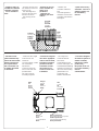
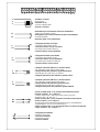
Trasformazione da barriera destra a sinistra
- Transformation of barrier from right to left -
Transformation de barrière droite à
barrière gauche -
Umbau von Rechts- zu Links-Schranke
- Transformación de barrera derecha a izquierda

6
B
C
B
D
E
A
A
B
D
E
C
B
Barriera destra
Right-hand barrier
Barrière droite
Rechts-Schranke
Barrera derecha
Barriera sinistra
Left-hand barrier
Barrière gauche
Links-Schranke
Barrera izquierda
PortaPorta
PortaPorta
Porta
Door
PortePorte
PortePorte
Porte
Tür
PuertaPuerta
PuertaPuerta
Puerta
Ammortizzatore
superiore
Vite
Ammortizzatore
inferiore
Gruppo porta-
finecorsa
Braccio motore
A
B
C
D
E
Upper shock
absorber
Screw
Lower shock
absorber
Limit witch holder
Motor arm
A
B
C
D
E
Amortisseur
supérieur
Vis
Amortisseur
inferieur
Groupe porte-fin
de course
Bras moteur
A
B
C
D
E
Oberer
Stoßdämpfer
Schraube
Unterer
Stoßdämpfer
Endschalter-
Einheit
Motor-Hebelarm
A
B
C
D
E
Amortiguador
superior
Tornillo
Amortiguador
inferior
Grupo fin de
carrera
Brazo motor
A
B
C
D
E

7
Chiusura
Closed position
Fermeture
Schließung
Cierre
Apertura
Open position
Ouverture
Öffnung
Apertura
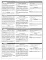
Applicazione su aste superiori a 1.8 m.
Installation on gate rod with height exceeding 1.8 m.
Application sur lisse de plus de 1.8 m.
Anbringung bei über 1.8 m hohen Stangenlänge.
Aplicación en barra superiores a 1.8 m.
Collaudi -
Testing
- Essais -
Betriebskontrollen
- Pruebas
Comprobar:
- la linearidad de la
barra en posición de
apertura (en caso,
ajustar el
amortiguador inferior
y enroscar el tornillo
correspondiente);
- la linearidad de la
barra en posición de
cierre (en caso,
ajustar el
amortiguador
superior y enroscar el
tornillo
correspondiente).
Überprüfen Sie:
- die Linearität des
Schrankenbaums in
Öffnungsstellung (den
unteren Stoßdämpfer,
falls erforderlich,
einstellen und die
entsprechende
Schraube festziehen);
- die Linearität des
Schrankenbaums in
Schließstellung (den
oberen Stoßdämpfer,
falls erforderlich,
einstellen und die
entsprechende
Schraube festziehen);
Vérifier:
- la verticalité de la
lisse en position d'ou-
verture (en cas, régler
l'amortisseur inférieur
et visser la vis
correspondante);
- l'horizontalité de la
lisse en
position de
fermeture (en cas,
régler l'amortisseur
supérieur et visser la
vis correspondante).
Check also:
- make sure that the
barrier rod is perfectly
vertical when placed in
the
open position (if
necessary, adjust the
lower shock absorber
and tighten the relative
screw);
- make sure that the
barrier rod is perfectly
horizontal when placed
in the
closed position
(if necessary, adjust
the upper shock
absorber and tighten
the relative screw).
Verificare:
- la linearità dell'asta
in posizione di aper-
tura (in caso regolare
l'ammortizzatore infe-
riore e avvitare la re-
lativa vite);
- la linearità dell'asta
in posizione di
chiu-
sura (in caso regola-
re l'ammortizzatore
superiore e avvitare
la relativa vite).
Bilanciamento -
Balancing
- Equilibrage -
Ausgleich
- Equilibración
Per un corretto fun-
zionamento della
sbarra automatica si
devono seguire le
condizioni di
«bilanciamento mol-
la».
In order to assure
correct operation of the
automatic barrier, the
spring position must be
matched with the
length of the barrier.
Pour que la barrière
automatique fonctionne
correctement, il est
nécessaire de
respecter les
conditions déquilibrage
du ressort.
Zur Gewährleistung
eines einwandfreien
Betriebs des
Schrankenantriebs
sollten die betreffenden
Richtlinien zum
Federausgleich.
Para el correcto
funcionamiento de la
barra automática se
deben respetar las
normas para la
«equilibración del
muelle».
Applicazione su aste inferiori a 1.8 m.
Installation on gate rod with height less than 1.8 m.
Application sur lisse de moins de 1.8 m.
Anbringung bei unter 1.8 m hohen Stangenlänge.
Aplicación en barra inferiores a 1.8 m.

8
Progettato e costruito interamente dalla
CAME, motoriduttore con finecorsa mec-
canici ed elettrici.
Il quadro comando va alimentato a (230V
a.c.) sui morsetti L1 e L2 ed è protetto in
ingresso con fusibile di linea da 5A.
I dispositivi di comandi sono a bassa ten-
sione (24V), protetti con fusibile da 1.6A,
con possibilità di utilizzare la stessa per
l'alimentazione dei vari accessori (radio-
comandi, fotocellule ecc.). La potenza
complessiva degli accessori a 24V, non
deve superare i 20W.
Sicurezza
Le fotocellule possono essere collegate e
predisposte in riapertura in fase di chiusu-
ra.
Funzioni selezionabili
-Funzionamento a «uomo presente» (ta-
gliare nei punti contassegnati con una "
sulla scheda).
Altre funzioni e accessori
- Chiusura automatica. Il temporizzatore di
chiusura automatica si autoalimenta a
finecorsa in apertura. Il tempo prefissato
regolabile, é comunque subordinato dal-
l'intervento di eventuali accessori di
sicurezza e si esclude dopo un intervento
di «stop» totale o in mancanza di energia
elettrica;
- In caso di applicazione di un lampeggia-
tore, possibilità di prelampeggio nella fase
di chiusura;
Designed and built entirely by CAME,
gear motor with mechanical limit switches
and electronic control of the running cycle.
This control board is powered by 230V a.c.
across terminals L1 and L2, and is
protected by a 5A fuse on the main power
line. The controls operate at a low voltage
(24V) protected by a 1.6A fuse; the same
low voltage can be used to feed the
various other accessories (radio controls,
photocells, etc.).
The total power consumption of 24 V
accessories must not exceed 20 W.
Safety
Photocells can be connected to obtain:
-Re-opening during the closing cycle;
Functions available
- “Human presence” operation (cut in the
points marked " on the diagram).
Other functions
- Automatic closing: The automatic
closing timer is automatically activated at
the end of the opening cycle. The preset,
adjustable automatic closing time is
automatically interrupted by the activation
of any safety system, and is deactivated
after a total stop command or in case of
power failure;
- When a flashing ligh is applied, pre-
flashing is possible in the closing phase;
- The unit is preset for a receiver with
one- or two-channel connection;
- Selection of command sequence only
for radio controls:
-open-close-reverse.
Adjustments
- Trimmer TCA = Automatic closing time:
5" to 90";
- Trimmer T.P. = Pre-flashing time: 0" to
5".
Important: disconnect the unit from the
main power lines before carrying out any
operation inside the unit.
La carte est entièrement conçue et
fabriquée par CAME S.p.A., motoré-
ducteur avec fin de course mécaniques
et électronique.
La carte de commande doit être alimentée
avec une tension de 230V sur les bornes
L1 et L2 et elle est protégée en entrée
par un fusible de ligne de 5A. Les
dispositifs de commande sont à basse
tension (24V) et protégés avec fusible
de1.6A; on peut utiliser cette tension pour
alimenter différents accessoires
(radiocommandes, photocellules, etc.). La
puissance totale des accessoires à 24V,
ne doit pas dépasser 20W.
Sécurité
Il est possible de brancher des
photocellules et de les programmer en
réouverture en phase de fermeture;
Fonctions sélectionnées
- Fonctionnement “personne présente”
(couper aux points marqués avec " sur la
carte).
Autres fonctions
- Fermeture automatique. Le
temporisateur de fermeture automatique
est autoalimenté à la fin du temps de la
course en ouverture. Le temps réglable
est programmé, cependant, il est sub-
ordonné à l’intervention d’éventuels
accessoires de sécurité et il est exclu
après une intervention de “stop” total ou
en cas de coupure de courant;
- En cas d'application d'un clignotant,
possibilité de préclignotement pendant la
fermeture;
- Équipement pour un récepteur à
- Predisposizione per ricevitore ad innesto
mono o bicanale;
-Tipo di comando solo per radiocomando
innestato:
- apre-chiude-inversione;
Regolazioni
- Trimmer TCA = Tempo chiusura automa-
tica: da 5" a 90";
- Trimmer T.P. = Tempo prelampeggio: da
0" a 5".
Attenzione: prima di intervenire all’intero
dell' apparecchiatura, togliere la tensione.
branchement mono/bicanal;
- Types de commande seulement pour
radiocommandes:
-ouverture - fermeture - inversion.
Réglages
- Trimmer T.C.A. = Temps de fermeture
automatique : de 5" à 90"
- Trimmer T.P. = Temps de Précligniton:
0" à 5".
Attention: couper la tension avant d'in-
tervenir à l'intérieur de l'appareillage.
Vollkommen von der CAME S.p.A. den
geltenden, Getriebemotor mit mech-
anischen und elektronische End-
anschlägen.
Die grundplatine wird mit einer Spannung
von 230V über die Klemmen L1 und L2
gespeist und ist am Eingang mit einer 5A-
Hauptsicherung. Der Steuerkreis wird mit
Niederspannung (24V) versorgt und durch
enie 1.6A-Sicherung geschützt; er dient
ebenfalls zur Stromversogung der
eventuellen Photozelle, Funksteuerung.
Die Gesamtleistung des 24-V-Zubehörs
darf 20W nicht überschreiten.
Sicherheitsvorrichtungen
Die Lichtschranken können für folgende
Funktionen angeschlossen bzw.
vorbereitet werden:
-Wiederöffnen beim Schließen;
Wahlfunktionen
- Funktion “Bedienung vom Steuerpult”
(auf der Steuerkarte an der mit dem
Symbol ");
Andere Funktionen
- Schließautomatik. Der
Schließautomatik-Zeischalter speist sich
beim Öffnen am Ende der Torlaufzeit
selbst . Die voreingestellte Zeit ist auf
jeden Fall immer dem Eingriff eventueller
Sicherheitsvorrichtungen untergeordnet
und schließt sich nach einem “Stop”Total-
Eingriff bzw. bei Stromausfall selbst aus;
- Falls das Lichtsignalgerät angebracht
wird, ist während der Schliessungszeit ist
die Möglichkeit des Vorblinkens gegeben;
- Steckleiste für Funkempfänger mono/
bicanal;
- Steuerart nur für Funksteuerung:
-Öffnen - Schließen -
Torlaufumsteuerung.
Einstellungen
- Trimmer TCA = Zeiteinstellung Schließ-
automatik: von 5" bis 90";
- Trimmer T.P. = Vorblinkzeit: 0" bis 5".
Achtung: Vor Eingriff im Innern des
Gerätes den Netzstecker ziehen.
Technische beschreibung Schalttafel ZG2
DEUTSCH
Description technique armoire de commande ZG2
FRANÇAIS
Technical description ZG2 control panel
ENGLISH
Descrizione tecnica quadro comando ZG2
ITALIANO

9
Tagliare per la funzione "uomo presente"
Cut here to obtain the "man present" function
Enlever pour la fonction "personne présente"
Für Funktion "Bedienung vom Steuerpult" abtrennen
Cortar para la función "hombre presente"
Diseñado y fabricado enteramente por
CAME S.p.A., motorreductor con finales
de carrera mecánicos y electrónico.
La tarjeta de mando se alimenta con una
tensión de 230V en los bornes L1 y L2 y
está protegido en entrada con fusible de
línea de 5A. Los dispositivos de mando
son a baja tensión (24V), protegidos por
fusible a 1.6A, siendo posible utilizar ésta
misma para la alimentación de la posible
fotocélula, mando a distancia etc. La
potencia total de los accesorios a 24V,
no debe superar los 20W.
Seguridad
Las fotocélulas pueden estar conectadas
y predispuestas en reapertura en la fase
de cierre;
Funciones seleccionables
- Funcionamiento a “hombre presente”
(en la tarjeta de mando, recordar los
puntos marcados con el simbolo ").
Otras Funciones
- Cierre automático. El temporizador de
cierre automático se autoalimenta en fin-
de-tiempo carrera en fase de apertura. El
tiempo prefijado regulable, sin embargo,
está subordinado a la intervención de
posibles accesorios de seguridad y se
excluye después de una intervención de
parada total o en caso de falta de energía
eléctrica;
- Por la aplicación del indicator
intermitente, hay la posibilidad de pre-
intermitencia en la fase de cierre;
- Predisposición para radiorreceptor à
conexión mono/bicanal;
- Tipo de mando sólo para mando a
distancia:
-apertura-cierre-inversión.
Regulaciones
- Trimer TCA = Tiempo cierre
automático: de 5" a 90”;
- Trimmer T.P. = Tiempo
preintermitencia: de 0" a 5"
Cuidado: antes de intervenir en el
interior del aparato, hay que cortar la
tensión.
COLL.
VENT.
T.P.
T.C.A.
L1 L2 U V W
E
FA
FC 0 1 2 3
4
5T1T27
C
SB1B2
2
6
7
8
3
4
5
9
4
1
COMPOSANTS PRINCIPAUX
1 Transformateur
2 Trimmer T.P. régulation du temps de préclignotement
3 Trimmer T.C.A. régulation du temps de fermeture
automatique
4 Embrayage récepteur radio
5 Plaques à bornes pour le branchement de l'alimentation
et des accessories
6 Fusible de basse tension 1.6A
7 Fusibles ligne 5A
8 Plaques à bornes pour evéntoir
9 Fusibles de rechange
F
COMPONENTI PRINCIPALI
1 Trasformatore
2 Trimmer T.P. regolazione tempo prelampeggio
3 Trimmer T.C.A. regolazione tempo di chiusura auto-
matica
4 Innesto per ricevitore radio
5 Morsettiere di collegamento alimentazione ed acces-
sori
6 Fusibile bassa tensione 1.6A
7 Fusibili di linea 5A
8 Morsettiera collegamento per ventola
9 Fusibili di ricambio
I
COMPONENTI PRINCIPALI
1 Transformadore
2 Trimmer T.P. regulación tiempo de pre-lámpara
3 Trimmer T.C.A. regulación tiempo de cierre
automático
4 Conexión para radiorreceptor
5 Cajas de bornes conexión alimentación y accesorios
6 Fusible de baja tensión 1.6A
7 Fusibles de línea 5A
8 Cajas de bornes para aventador
9 Fusibles de recambio
E
HAUPTKOMPONENTEN
1 Trafo
2 Trimmer T.P. Eintellung Vorblinkzeit
3 Trimmer T.C.A. Einstellung Schließautomatikzeit
4 Steckleiste für Funkempfänger
5 Einspeisungsklemmenbretter und Zubehör
6 Niederspannungs-Sicherung 1.6A
7 Leitungs-Sicherungen 5A
8 klemmenbretter für Wedel
9 Austausch-Sicherungen
D
MAIN COMPONENTS
1 Transformer
2 Trimmer T.P. adjustments pre-flash-light time
3 Trimmer T.C.A. adjustments automatic closing time
4 Socket for radio receiver
5 Terminal block power suppply and accessories
6 1.6A low-tension fuse
7 5A line fuses
8 Terminal block for gauge box
9 Spare fuses
GB
N.B.: Coppia motore fissa: mantenere il faston indicato nella posizione 4.
N.B.: Fixed motor-torque: keep the fast-on as shown in position 4.
N.B.: Couple moteur fixe: maintenir la cosse indiquée en position 4.
Hinweis: Drehmoment fest montierter Motor: Den angegebenen Faston in Position 4 lassen.
Nota: Par motor fijo: mantenga el fastón indicado en la posición 4.
Descripción técnica cuadro de mando ZG2
ESPAÑOL

10
L1 L2
U
VW
E
FA
FC 0
1
23
4
5
T1
T2 7
C
S
B1
B2
W
E
L1
L2
0
1
1
2
2
3
2
4
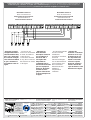
Alimentazione 230V (a.c.)
230V (a.c.) power input
Alimentation 230V (a.c.)
Stromversorgung 230V (Wechselstrom)
Alimentación 230V (a.c.)
Motore monofase 230V(a.c.)
230V (a.c.) single-phase motor
Moteur monophasé 230V (a.c.)
Einphasenmotor 230V (Wechselstrom)
Motor monofásico 230V (a.c.)
Uscita 230V a.c. in movimento (es.lampeggiatore)
230V (a.c.) output in motion (e.g. flashing light)
Sortie 230V (a.c.) en mouvement (ex. branchement clignotant)
Ausgang 230V (Wechselstrom) in Bewegung (z.B. Blinker-Anschluß)
Salida de 230V (a.c.) en movimento (p.ej. conexión lámpara
intermitente)
Alimentazione accessori 24V (a.c.) max. 20W
24V (a.c.)Powering accessories (max 20W)
Alimentation accessoires 24V (a.c.) max.20W
Zubehörspeisung 24V (Wechselstrom) max. 20W
Alimentación accesoios 24V (a.c.) max. 20W
Pulsante stop (N.C.)
Pushbutton stop (N.C.)
Bouton-poussoir arrêt (N.C.)
Stop-Taste (N.C.)
Pulsador de stop (N.C.)
Pulsante apre (N.O.)
Pushbutton opens (N.O.)
Bouton-possoir ouverture (N.O.)
Taste Öffnen (N.O.)
Pulsador de apertura (N.O.)
Pulsante chiude (N.O.)
Pushbutton closes (N.O.)
Bouton-poussoir fermeture (N.O.)
Taste Schließen (N.O.)
Pulsador de cierre (N.O.)
Contatto radio e/o pulsante apre-chiude-inversione
Contact radio and/or button control for "open-close-revere"
Contact radio et/ou poussoir "ouvre-ferme-inversion"
Funkkontakt und/oder Taste "Öffnen-Schließen-Umschalten"
Contacto radio y/o pulsador para "apertura-cierre-insersión"
Contatto (N.C.) di «riapertura durante la chiusura»
Contact (N.C.) for «re-aperture during closure»
Contact (N.C.) de «réouverture pendant la fermeture»
Kontakt (Ruhekontakt) Wiederöffnen beim Schliessen
Contacto (N.C.) para la apertura en la fase de cierre
2
7
2
C
U
W
V
10 11
RX
NO C NC
TX
N.B. Rispettare la polarità nel
collegamento delle
fotocellule (TX e RX).
N.B. When connecting the
photocells (TX and RX),
observe the correct polarities.
N.B. Respecter la polarité lors
de la connexion des
photocellules (TX et RX).
Anmerkung: beim Anschließen
der Photozellen (TX und RX)
auf die Polung achten.
N.B. Respetar la polaridad en
la conexión de las fotocélulas
(TX y RX).
Collegamenti elettrici //
Electrical connections
// Branchements électriques //
Elektrische anschlüsse
// Conexions eléctricas

11
L1 L2
U
VW
E
FA
FC 0
1
23
4
5
T1
T2 7
C
S
B1
B2
0
FC
0
FA
T1
T2
4
3
2
Selettore a chiave
Key selector
Sélecteur à clé
Schlüssel-Wahlschlter
Selector con llave
Interruttore per inserimento chiusura automatica
Switch for automatic closure
Interrupteur pour branchement fermeture automatique
Schließautomatik
Interrutor para cierre automático
Collegamento finecorsa apre
Connection limit switch opens
Connexion fin de course ouverture
Anschluß Endschallter Öffnung
Conexión fin de carrera apertura
Collegamento finecorsa chiude
Connection limit switch closes
Connexion fin de course fermeture
Anschluß Endschallter Schließung
Conexión fin de carrera cierre
Lampada spia 24V (3W max.) cancello chiuso
24V (3W max.) gate-closed signal lamp
Lampe-témoin 24V (3W max.) portail fermeture
Signallampe 24V (3W max.), Schließen
Lampara indicadora 24V (3W max.) puerta cierre
Lampada spia 24V (3W max.) cancello aperto
24V (3W max.) gate-opened signal lamp
Lampe-témoin 24V (3W max.) portail ouvert
Signallampe 24V (3W max.), offenes Tor
Lampara indicadora 24V (3W max.) puerta abierta
Uscita contatto (N.O.) con ricevitore bicanale ad innesto.
Portata contatto: 1A a 24V(d.c.)
Contact output (N.O.) with plug-in two-channel receiver.
Resistive load: 1A 24V (d.c.)
Sortie contact (N.O.) avec rècepteur bicanal à branchement.
Portée contact: 1A a 24V(d.c.)
Ausgang Arbeitskontakt mit Doppelkanal-Steck-Funkempfänger.
Stromfestigkeit: 1A bei 24V (Gleichstrom)
Salida contacto (N.O.) con receptor bicanal con inserción directa.
Carga resistiva: 1A a 24V(d.c.)
Collegamento antenna
Antenna connection
Connexion antenne
Antennenanschluß
Conexión antena
B1
B2
1
FC
1
FA

Tutti i dati sono stati controllati con la
massima cura. Non ci assumiamo co-
munque alcuna responsabilità per
eventuali errori od omissioni.
All data checked with the maximum care.
However, no liability is accepted for any error
or omission.
Toutes les données ont été contrôlées
très soigneusement. Nous n’assumons
de toute façon aucune responsabilité pour
les erreurs ou omissions éventuelles.
Die Daten wurden mit höchster Sorgfalt
geprüft. Für eventuelle Fehler oder
Auslassungen übernehmen wir keine
Haftung.
Todos los datos se han controlado con
la máxima atención. No obstante no nos
responsabilizamos de los posibles
errores u omisiones.
CANCELLI AUTOMATICI
CAME LOMBARDIA S.R.L.______COLOGNO M. (MI)
(+39) 02 26708293 (+39) 02 25490288
CAME SUD S.R.L. ___________________NAPOLI
(+39) 081 7524455 (+39) 081 7529109
CAME (AMERICA) L.L.C.____________MIAMI ( FL)
(+1) 305 5930227 (+1) 305 5939823
CAME AUTOMATISMOS S.A__________MADRID
(+34) 091 5285009 (+34) 091 4685442
CAME BELGIUM__________________LESSINES
(+32) 068 333014 (+32) 068 338019
CAME FRANCE S.A.____NANTERRE CEDEX (PARIS)
(+33) 01 46130505 (+33) 01 46130500
CAME GMBH________KORNTAL BEI (STUTTGART)
(+49) 07 11839590 (+49) 07 118395925
CAME GMBH____________SEEFELD BEI (BERLIN)
(+49) 03 33988390 (+49) 03 339885508
CAME PL SP.ZO.O______________WARSZAWA
(+48) 022 8365076 (+48) 022 8369920
CAME UNITED KINGDOM LTD___NOTTINGHAM
(+44) 0115 9210430 (+44) 0115 9210431
CAME CANCELLI AUTOMATICI S.P.A.
DOSSON DI CASIER (TREVISO)
(+39) 0422 4940 (+39) 0422 4941
SISTEMA QUALITÀ
CERTIFICATO
ASSISTENZA TECNICA
NUMERO VERDE
800 295830
W
EB
www.came.it
E-MAIL
Morsettiera motore A
Motor A terminal block
Plaque à bornes du moteur A
Klemmbrett Motor A
Cuadro de bornes motor A
Morsettiera motore B
Motor B terminal block
Plaque à bornes du moteur B
Klemmbrett Motor B
Cuadro de bornes motor B
L1 L2 U V W
E
FA
FC 0 1 2 3
4
5 T1 T2 7 C S B1 B2
L1 L2 U V W
E
FA
FC 0 1 2 3
4
5T1T27
C
SB1B2
1-2 2-C2-72-4
2-3
Collegamento per 2 motori abbinati con comando unico //
Connections for 2 combined motors controlled together
//
Connexions pour 2 moteurs accouplés avec commande inique //
Anschluss für 2 parallelgeschaltete motoren mit
gemeinsamer steuerung
// Conexion para 2 motores acoplados con mando unico
- Eseguire i normali
collegamenti elettrici
sulle morsettiere A-B,
però con i dispositivi
di comando collegati
solo sulla morsettiera
A; poi connettere le
morsettiere come da
figura.
- Connect as per
normal use to terminals
A and B, but with the
control devices
connected to terminal
A only; then connect to
the terminals as shown
in the figure.
- Effectuer les
branchements
électriques normaux
sur les plaques à
bornes A et B à
l'exception des
dispositifs de
commande qui ne
doivent être branchés
que sur la plaque à
bornes A. Brancher
ensiute les deux
plaques à bornes de
la façon indiquée sur
la figure.
- Auf den Klemmleisten
A-B die normalen
elektrischen
Anschlüsse ausführen,
wobei die
Steuereinrichtungen
nur auf Klemmleiste A
anzuschließen sind.
Dann die beiden
Klemmleisten der
Abbildung
entsprechend
verbinden.
- Efectuar las
normales conexiones
eléctricas en la caja
de bornes A-B, con
los dispositivos de
mando conectados
sólo en la caja de
bornes A; posterior-
mente conectar las
cajas de bornes como
indicado en la figura.
-
 1
1
-
 2
2
-
 3
3
-
 4
4
-
 5
5
-
 6
6
-
 7
7
-
 8
8
-
 9
9
-
 10
10
-
 11
11
-
 12
12


CAME G2500 Le manuel du propriétaire
- Taper
- Le manuel du propriétaire
- Ce manuel convient également à
dans d''autres langues
- italiano: CAME G2500 Manuale del proprietario
- English: CAME G2500 Owner's manual
- español: CAME G2500 El manual del propietario
- Deutsch: CAME G2500 Bedienungsanleitung
Documents connexes
-
CAME ZC2-C Le manuel du propriétaire
-
-
-
-
-
-
-
CAME G4000 Manuel utilisateur
-
-