Multitech MTXDOT-NA1-A00-100 Mode d'emploi
- Taper
- Mode d'emploi

xDot
®
Developer Guide

MULTICONNECT XDOT DEVELOPER GUIDE
2 xDot
®
Developer Guide
MultiConnect xDot Developer Guide
Models: MTXDOT-NA1-xx , MTXDOT-EU1-xx , MTXDOT-AU1-xx, MTXDOT-AS1-xx , MTXDOT-EU1-IN1-xx , MTXDOT-KR1-xx
Part Number: S000645, Version 3.3
Copyright
This publication may not be reproduced, in whole or in part, without the specific and express prior written permission signed by an executive officer of
Multi-Tech Systems, Inc. All rights reserved. Copyright © 2019 by Multi-Tech Systems, Inc.
Multi-Tech Systems, Inc. makes no representations or warranties, whether express, implied or by estoppels, with respect to the content, information,
material and recommendations herein and specifically disclaims any implied warranties of merchantability, fitness for any particular purpose and non-
infringement.
Multi-Tech Systems, Inc. reserves the right to revise this publication and to make changes from time to time in the content hereof without obligation of
Multi-Tech Systems, Inc. to notify any person or organization of such revisions or changes.
Trademarks and Registered Trademarks
MultiTech, the MultiTech logo, MultiConnect, Conduit, and xDot are registered trademarks and mCard and mDot is a trademark of Multi-Tech Systems, Inc.
All other products and technologies are the trademarks or registered trademarks of their respective holders.
Legal Notices
The MultiTech products are not designed, manufactured or intended for use, and should not be used, or sold or re-sold for use, in connection with
applications requiring fail-safe performance or in applications where the failure of the products would reasonably be expected to result in personal injury or
death, significant property damage, or serious physical or environmental damage. Examples of such use include life support machines or other life
preserving medical devices or systems, air traffic control or aircraft navigation or communications systems, control equipment for nuclear facilities, or
missile, nuclear, biological or chemical weapons or other military applications (“Restricted Applications”). Use of the products in such Restricted
Applications is at the user’s sole risk and liability.
MULTITECH DOES NOT WARRANT THAT THE TRANSMISSION OF DATA BY A PRODUCT OVER A CELLULAR COMMUNICATIONS NETWORK WILL BE
UNINTERRUPTED, TIMELY, SECURE OR ERROR FREE, NOR DOES MULTITECH WARRANT ANY CONNECTION OR ACCESSIBILITY TO ANY CELLULAR
COMMUNICATIONS NETWORK. MULTITECH WILL HAVE NO LIABILITY FOR ANY LOSSES, DAMAGES, OBLIGATIONS, PENALTIES, DEFICIENCIES, LIABILITIES,
COSTS OR EXPENSES (INCLUDING WITHOUT LIMITATION REASONABLE ATTORNEYS FEES) RELATED TO TEMPORARY INABILITY TO ACCESS A CELLULAR
COMMUNICATIONS NETWORK USING THE PRODUCTS.
The MultiTech products and the final application of the MultiTech products should be thoroughly tested to ensure the functionality of the MultiTech
products as used in the final application. The designer, manufacturer and reseller has the sole responsibility of ensuring that any end user product into
which the MultiTech product is integrated operates as intended and meets its requirements or the requirements of its direct or indirect customers.
MultiTech has no responsibility whatsoever for the integration, configuration, testing, validation, verification, installation, upgrade, support or maintenance
of such end user product, or for any liabilities, damages, costs or expenses associated therewith, except to the extent agreed upon in a signed written
document. To the extent MultiTech provides any comments or suggested changes related to the application of its products, such comments or suggested
changes is performed only as a courtesy and without any representation or warranty whatsoever.
Contacting MultiTech
Knowledge Base
The Knowledge Base provides immediate access to support information and resolutions for all MultiTech products. Visit http://www.multitech.com/kb.go.
Support Portal
To create an account and submit a support case directly to our technical support team, visit: https://support.multitech.com.
Support
Business Hours: M-F, 8am to 5pm CT
Country By Email By Phone
Warranty
To read the warranty statement for your product, visit https://www.multitech.com/legal/warranty. For other warranty options, visit
www.multitech.com/es.go.
World Headquarters
Multi-Tech Systems, Inc.
2205 Woodale Drive, Mounds View, MN 55112
Phone: (800) 328-9717 or (763) 785-3500
Fax (763) 785-9874

CONTENTS
xDot
®
Developer Guide 3
Contents
Chapter 1 – Product Overview ................................................................................................................................. 7
Overview ....................................................................................................................................................................... 7
What's New in Firmware Version 3.2 ........................................................................................................................... 7
LoRaWAN Version 1.0.3 Class B Support .................................................................................................................... 7
Russian Channel Plan Support .................................................................................................................................... 7
AT Command Additions and Modifications ................................................................................................................ 7
Documentation Overview ............................................................................................................................................. 8
Related Documentation .............................................................................................................................................. 8
mbed Documentation ................................................................................................................................................... 8
Programming the xDot Microcontroller ..................................................................................................................... 8
General mBed Links .................................................................................................................................................... 9
xDot Platform ............................................................................................................................................................. 9
EUI and Networking ...................................................................................................................................................... 9
Product Build Options ................................................................................................................................................. 10
Chapter 2 – Getting Started ................................................................................................................................... 11
Getting Started with the xDot Developer Kit.............................................................................................................. 11
COM Port Enumeration by Operating System ............................................................................................................ 11
Linux.......................................................................................................................................................................... 11
Windows ................................................................................................................................................................... 11
Mac ........................................................................................................................................................................... 12
Updating Firmware Using the xDot Bootloader ......................................................................................................... 12
Chapter 3 – Mechanical Drawings with Pinouts ..................................................................................................... 14
xDot............................................................................................................................................................................. 14
Chapter 4 – Specifications and Pin Information...................................................................................................... 15
MTXDOT Specifications ............................................................................................................................................... 15
North American Models (MTXDOT-NA1) ................................................................................................................. 16
European Models (MTXDOT-EU) .............................................................................................................................. 17
Australian Models (MTXDOT-AU1) ........................................................................................................................... 18
Indian Models (MTXDOT-EU1-IN1) ........................................................................................................................... 19
South Korean Models (MTXDOT-KR1) ...................................................................................................................... 20
Asia Pacific Models (MTXDOT-AS1) .......................................................................................................................... 20
Battery Draw Down..................................................................................................................................................... 22
Electrical and Timing Characteristics ........................................................................................................................ 22
Measuring the Power Draw ...................................................................................................................................... 23
Pin Information .......................................................................................................................................................... 24
Pin Information ......................................................................................................................................................... 24
Pull-Up/Down............................................................................................................................................................ 26

CONTENTS
4 xDot
®
Developer Guide
LoRa ........................................................................................................................................................................... 26
Crystals/Oscillator ..................................................................................................................................................... 26
Sleep Wake and Deep Sleep Wake Pins ................................................................................................................... 26
Interrupt Limitations ................................................................................................................................................. 27
xDot Pinout Design Notes ........................................................................................................................................... 28
Serial Pinout Notes.................................................................................................................................................... 28
Serial Settings.............................................................................................................................................................. 28
LoRa ............................................................................................................................................................................ 28
Throughput Rates...................................................................................................................................................... 28
Range ........................................................................................................................................................................ 28
Resetting the xDot ...................................................................................................................................................... 30
Chapter 5 – Antennas ............................................................................................................................................ 31
Antenna System ......................................................................................................................................................... 31
U.FL and Trace Antenna Options ............................................................................................................................... 31
Pulse Electronics Antenna........................................................................................................................................... 32
Antenna Specifications ............................................................................................................................................. 32
RSMA-to-U.FL Coaxial Cables ..................................................................................................................................... 33
Coaxial Cable Specifications ..................................................................................................................................... 33
Ethertronics Chip Antenna.......................................................................................................................................... 34
Antenna Specifications ............................................................................................................................................. 34
Stackup Information.................................................................................................................................................... 34
Developer Board Layer Stackup................................................................................................................................ 34
Stackup Table ............................................................................................................................................................ 35
Impedance ................................................................................................................................................................ 35
Chip Antenna Design Guidelines................................................................................................................................. 37
Antenna Pad Layout.................................................................................................................................................. 38
PCB Layout ................................................................................................................................................................ 38
Antenna Matching Network........................................................................................................................................ 39
915 ............................................................................................................................................................................ 39
868 ............................................................................................................................................................................ 40
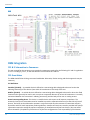
OEM Integration ......................................................................................................................................................... 40
FCC & IC Information to Consumers ......................................................................................................................... 40
FCC Grant Notes........................................................................................................................................................ 40
Host Labeling............................................................................................................................................................... 41
Chapter 6 – Safety Information .............................................................................................................................. 42
Handling Precautions .................................................................................................................................................. 42
Radio Frequency (RF) Safety ....................................................................................................................................... 42
Sécurité relative aux appareils à radiofréquence (RF).............................................................................................. 42
Interference with Pacemakers and Other Medical Devices ...................................................................................... 43
Potential interference............................................................................................................................................... 43
Precautions for pacemaker wearers ........................................................................................................................ 43

CONTENTS
xDot
®
Developer Guide 5
Device Maintenance ................................................................................................................................................... 43
User Responsibility...................................................................................................................................................... 44
Chapter 7 – Regulatory Information....................................................................................................................... 45
EMC, Safety, and Radio Equipment Directive (RED) Compliance .............................................................................. 45
47 CFR Part 15 Regulation Class B Devices ................................................................................................................. 45
FCC Interference Notice ............................................................................................................................................. 45
FCC Notice................................................................................................................................................................... 45
Industry Canada Class B Notice................................................................................................................................... 46
Chapter 8 – Environmental Notices........................................................................................................................ 47
Waste Electrical and Electronic Equipment Statement .............................................................................................. 47
WEEE Directive.......................................................................................................................................................... 47
Instructions for Disposal of WEEE by Users in the European Union ........................................................................ 47
REACH Statement ....................................................................................................................................................... 47
Registration of Substances........................................................................................................................................ 47
Restriction of the Use of Hazardous Substances (RoHS) ............................................................................................ 47
Information on HS/TS Substances According to Chinese Standards ......................................................................... 49
Information on HS/TS Substances According to Chinese Standards (in Chinese) ...................................................... 50
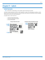
Chapter 9 – Labels.................................................................................................................................................. 51
Label Examples............................................................................................................................................................ 51
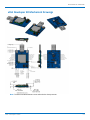
Chapter 10 – Developer Kit Overview .................................................................................................................... 52
xDot Developer Kit ..................................................................................................................................................... 52
Developer Kit Package Contents............................................................................................................................... 52
Firmware Updates..................................................................................................................................................... 52
Programming Devices in Production ........................................................................................................................ 52
xDot Developer Kit Mechanical Drawings................................................................................................................... 53
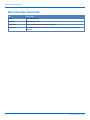
Micro Developer Board LEDs ...................................................................................................................................... 54
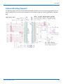
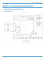
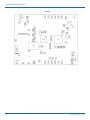
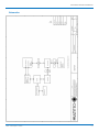
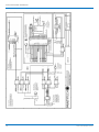
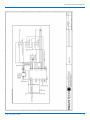
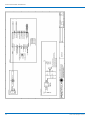
Chapter 11 – Developer Board Schematics............................................................................................................. 55
Assembly Diagrams and Schematics ........................................................................................................................... 55
Assembly Diagrams ................................................................................................................................................... 55
Schematics ................................................................................................................................................................ 57
Chapter 12 – Design Considerations....................................................................................................................... 61
Noise Suppression Design ........................................................................................................................................... 61
PC Board Layout Guideline ......................................................................................................................................... 61
Electromagnetic Interference .................................................................................................................................... 61
Electrostatic Discharge Control................................................................................................................................... 62
Chapter 13 – Mounting xDots and Programming External Targets ......................................................................... 63
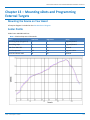
Mounting the Device on Your Board .......................................................................................................................... 63
Solder Profile............................................................................................................................................................... 63
Setpoints (Celsius)..................................................................................................................................................... 64
xDot Packing ............................................................................................................................................................... 64

CONTENTS
6 xDot
®
Developer Guide
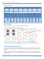
In-System Programming of xDot................................................................................................................................. 64
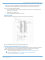
Schematic Example ................................................................................................................................................... 65
Recommended Programming Hardware for Production.......................................................................................... 65
JTAG/SWD Connector .............................................................................................................................................. 66
Chapter 14 – Appendix A Release Note Archive ..................................................................................................... 67
What's New in Firmware Version 3.0 ......................................................................................................................... 67
LoRaWAN 1.0.2 Support ........................................................................................................................................... 67
Listen Before Talk ..................................................................................................................................................... 67
Separate Channel Plans ............................................................................................................................................ 67
What's New in Firmware Version 3.1 ......................................................................................................................... 67
xDot Bootloader........................................................................................................................................................ 67
Power Optimization .................................................................................................................................................. 67
Other Enhancements ................................................................................................................................................ 68
Index...................................................................................................................................................................... 69

PRODUCT OVERVIEW
xDot
®
Developer Guide 7
Chapter 1 – Product Overview
Overview
The MultiConnect xDot (MTXDOT) is a LoRaWAN
TM
, low-power RF device, capable of two way communication over
long distances, deep into buildings, or within noisy environments
*
using the unlicensed ISM bands in North
America, Europe and worldwide. The xDot is a compact surface-mount device with an mbed enabled processor and
enhanced security. The xDot features an integrated ARM
®
Cortex
®
-M3 processor and mbed
TM
compatible software
library for developers to control, monitor and bring edge intelligence to their Internet of Things (IoT) applications.
*
Actual distance depends on conditions, configuration, antennas, desired throughput, and usage frequency. In
dense urban environments, a typical range is 1-2 miles.
What's New in Firmware Version 3.2
The new release includes the following changes:
LoRaWAN Version 1.0.3 Class B support
Russian channel plan support
New and updated AT Commands
LoRaWAN Version 1.0.3 Class B Support
The LoRaWAN Class B option allows devices to open receive windows at fixed time intervals for server-initiated
downlink messages.
New AT Commands: +PP - Ping slot periodicity and +BLS - Beacon lock status
Russian Channel Plan Support
RU864-870 ISM band channel frequencies as described in LoRaWAN Version 1.0.3. This allows devices to operate in
the 864 to 870 MHz frequency band and store parameters for at least eight channels.
AT Command Additions and Modifications
Note: For AT Command details, refer to S000643 DOT Series AT Command Reference Guide .
Deprecated AT+RECVC and AT+RXF in production firmware versions
Deprecated AT+AS.
Added AT+PP - Ping slot periodicity.
Added AT+FO - Frequency offset.
Added AT+GPSTIME - Retrieving GPS synchronized time.
Added AT+BAT - Device battery level.
Added AT+BLS - Get the beacon's lock status
Added AT+LBTRSSI - Listen Before Talk RSSI
Added AT+SENDC - Sends data continuously
Changed AT+RXO - Receive output
For an archive of release notes, go to Appendix A.

PRODUCT OVERVIEW
8 xDot
®
Developer Guide
Documentation Overview
This manual is one part of xDot documentation. Refer to the Related Documentation and mbed sections for
additional information needed to program your xDot and integrate your application with the MultiConnect Conduit
gateway.
This document includes:
xDot device information: including mechanical drawings, specifications, safety and regulatory information,
and other device specific content.
Developer Kit information: including design considerations, schematics, and installation and operation
information.
This current version of this manual is available at www.multitech.com/support.
Related Documentation
DOT Series AT Command Reference: Includes details on the AT commands available for xDots.
MultiTech Developer Site: Application notes, LoRa information, and documentation for related products
such as the MultiConnect Conduit (MTCDT) gateway and the LoRa accessory card (MTAC-LORA) are available
on the MultiTech developer site. This site includes information on using the Conduit with xDots. Go to:
www.multitech.net
Processor Datasheet: ST ARM
®
Cortex
®
-M3 processor (STM32L151CCU6) datasheet is available on the ST
website: http://www.st.com/resource/en/datasheet/stm32l151cc.pdf
mbed Documentation
ARM mbed is a free, open-source platform and operating system for embedded devices using the ARM Cortex-M
microcontrollers. The mbed website provides free software libraries, hardware designs, and online tools for rapid
prototyping of products. The platform includes a standards-based C/C++ SDK, a microcontroller HDK, and
supported development boards, an online compiler and online developer collaboration tools.
Note: To send and receive data, you need a LoRaWAN 1.0 gateway, such as MultiTech's MultiConnect Conduit
(MTCDT) with an MTAC-LORA accessory card installed.
Programming the xDot Microcontroller
Note: To program an xDot application, you need the xDot Developer kit, which includes an xDot mounted on a
developer board.
Use the ARM mbed ecosystem to program the microcontroller. Compile in the cloud or locally, copy the resulting
binary file to the mbed USB drive, and reset the xDot.
On the xDot mbed page, MultiTech supplies source code for non-RF portions of the xDot. To comply with FCC and
ETSI certification, some portions of the software is available only as binary libraries.
MultiTech offers both development and stable release versions of the library.
Development version: libmxDot-dev-mbed5
Stable release version: libmxDot-mbed5
You can use either the mbed online compiler or offline tools.
Online: Use the mbed-os library in your mbed application

PRODUCT OVERVIEW
xDot
®
Developer Guide 9
Offline: Use mbed-cli tools to create, manage, and build your mbed 5.1 application.
General mBed Links
Explore mbed: http://developer.mbed.org/explore
Getting Started with mbed: http://developer.mbed.org/getting-started
mbed Handbook: http://developer.mbed.org/handbook/Homepage
mbed online compiler documentation: https://developer.mbed.org/handbook/mbed-Compiler
mbed cli documentation: https://github.com/ARMmbed/mbed-cli/blob/master/README.md
mbed workspace tools documentation: https://github.com/ARMmbed/mbed-
os/blob/master/docs/BUILDING.md#workspace-tools
xDot Platform
The xDot mbed page includes the xDot library, firmware, and test cases
https://developer.mbed.org/platforms/MTS-xDot-L151CC/
EUI and Networking
xDots have an Extended Unique Identifier (EUI). To query the device for the EUI, AT+DI:
AT+DI=<8-BYTE-HEX-MSB>
AT+DI=001122AABBCCDDEE
For information on setting up xDots as part of a LoRa network, go to www.multitech.net.

PRODUCT OVERVIEW
10 xDot
®
Developer Guide
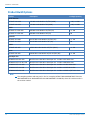
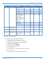
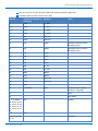
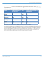
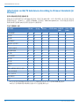
Product Build Options
Product Description Package Quantity
North America
MTXDOT-NA1-A00 915 MHz LoRa Module UFL/TRC (NAM) 1, 100, or 1000
MTXDOT-NA1-A01 915 MHz LoRa Module TRC (NAM) 1, 100, or 1000
EMEA
MTXDOT-EU1-IN1-A00 868 MHz LoRa Module UFL/TRC (EU) 1 or 100
MTXDOT-EU1-IN1-A01 868 MHz LoRa Module TRC (EU) 100
Australia
MTXDOT-AU1-A00 AU915 MHz LoRa Module UFL/TRC (AU) 1 or 100
MTXDOT-AU1-A01 AU915 MHz LoRa Module TRC (AU) 100
AS923
MTXDOT-AS1-A00 AS923 MHz LoRa Module UFL/TRC (APAC) 1 or 100
Korea
MTXDOT-KR1-A00 KR920 MHz LoRa Module w/LBT UFL/TRC (KR) 1 or 100
Developer Kits
MTMDK-XDOT-NA1-A00 MultiConnect xDot Micro Developer Kit - Includes a 915 MHz xDot
MTMDK-XDOT-EU1-IN1-A00 MultiConnect xDot Micro Developer Kit - Includes a 868 MHz xDot
MTMDK-XDOT-AU1-A00 MultiConnect xDot Micro Developer Kit - Includes a AU915 MHz xDot
MTMDK-XDOT-AS1-A00 MultiConnect xDot Micro Developer Kit - Includes a AS923 MHz xDot
MTMDK-XDOT-KR1-A00 MultiConnect xDot Micro Developer Kit - Includes a KR920 w/LBT MHz xDot
Note:
The complete product code may end in .Rx. For example, MTXDOT-NA1-A00.RxMTXDOT-EU1-IN1-
A00.RxMTXDOT-AU1-A00.RxMTXDOT-AS1-A00.RxMTXDOT-JP1-A00.Rx, where R is revision and x is
the revision number.

GETTING STARTED
xDot
®
Developer Guide 11
Chapter 2 – Getting Started
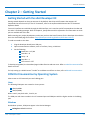
Getting Started with the xDot Developer Kit
Getting started depends on what you want to do. By default, xDot ships with firmware that supports AT
Commands that use the serial I/O. For AT Commands, refer to the separate MultiConnect Dots AT Command
Reference Guide.
Two serial interfaces are available through the USB interface, one is used to send AT commands to the xDot and
the other is for debug messages. Refer to Chapter 4, Specifications and Pin Information for information on which
pins are available out of the box.
Before starting your project development, make sure you have the latest firmware for the Developer Kit and xDot.
Go to the xDot mbed page for firmware. https://developer.mbed.org/platforms/MTS-xDot-L151CC/
To send commands to the xDot:
1. Plug the developer board into a USB port.
2. Open communications software, such as TeraTerm, Putty, or Minicom.
3. Set the following:
Baud rate = 115,200
Data bits = 8
Parity = N
Stop bits = 1
Flow control = Off
To develop using Mbed, the xDot Mbed page includes libraries and test cases. Refer to mbed Documentation for
details and links.
For help setting up a MultiConnect
®
Conduit
®
to send data to and from an xDot, refer to Related Documentation .
COM Port Enumeration by Operating System
xDots create an AT Commands port and a debug port.
Linux
The following COM ports are created on Linux systems:
/dev/ttyACMx
/dev/ttyACMy
Where x and y may be 0 and 1, 3 and 4, etc.
The COM port with lower number is the AT command port and COM port with the higher number is the debug
port.
Windows
On Windows systems, COM ports appear in the Device Manager:
Debug Port: Mbed Serial Port

GETTING STARTED
12 xDot
®
Developer Guide
AT Command Port: XR21V1410 USB UART
You may need to install a driver for the debug port to function properly. Go to:
https://developer.Mbed.org/handbook/Windows-serial-configuration
Mac
On Mac systems, COM ports appear in the Device Manager as:
/dev/cu.usbmodemx
Where x is a string of numbers and possibly letters, ending in a number.
The COM port with lower number is the AT command port and COM port with the higher number is the debug
port.
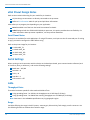
Updating Firmware Using the xDot Bootloader
The xDot bootloader allows firmware upgrades either via YMODEM through command or debug serial ports at
115,200 bps.
To enter the bootloader, enter the characters xdt on either serial port upon processor reset. The bootloader allows
250ms for x and then 500 ms each for d and t. If these timers expire before receiving the proper character or
another character is received, the bootloader jumps to the application code.
The bootloader includes an option to upgrade application code via YMODEM or jump to the application
code. During the YMODEM file transfer, the new application is programmed directly into the STM32L151CC
flash memory.
Since the new application is directly programmed into the STM32L151CC flash memory and the xDot has no
on board memory to back up the old application, recovery from failed download is the responsibility of the
host system.
The Mbed build process creates two files when building for the bootloader. The
name_of_program_application.bin file is the application with the correct offset that can be transferred via
YMODEM onto the xDot using the bootloader. The name_of_program.bin file is the entire program with the
bootloader than can be flashed on using jtag (this file cannot be transferred onto the xdot via YMODEM).
To build xDot firmware with the bootloader, you must include the bootloader.bin file in the Mbed-os directory
along with an Mbed_app.json file that includes directives describing the space used for the bootloader and the
location where the bootloader.bin file resides.
Note: For an application to run at the correct offset, it needs location where it will reside so the vector
table is correct.
Mbed-os version 5.5.4, includes hooks that allow you to easily add a boot loader for the xDot. Go to
https://docs.Mbed.com/docs/Mbed-os-handbook/en/latest/advanced/bootloader/ for details.
For the bootloader, create a file with the following content. (Actual size may vary, but needs to
accommodate the bootloader size.) Name the file Mbed_app.json and place it in the root directory.
{
"target_overrides": {
"XDOT_L151CC": {
"target.restrict_size": "0x8000"
}
}

GETTING STARTED
xDot
®
Developer Guide 13
}
For the application, create a file with the following content. Name it Mbed_app.json and place it in the root
directory.
{
"target_overrides": {
"XDOT_L151CC": {
"target.bootloader_img": "bootloader_location/bootloader.bin"
}
}
}

MECHANICAL DRAWINGS WITH PINOUTS
14 xDot
®
Developer Guide
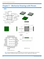
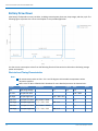
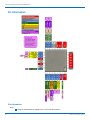
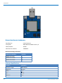
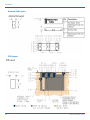
Chapter 3 – Mechanical Drawings with Pinouts
xDot
Note: The xDot development board uses a land pattern that matches the xDot land pattern in the previous
image. All pads are 0.028 inches square except the large one, which is 0.098 inches x 0.028 inches.

SPECIFICATIONS AND PIN INFORMATION
xDot
®
Developer Guide 15
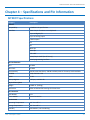
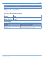
Chapter 4 – Specifications and Pin Information
MTXDOT Specifications
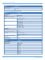
Category Description
General
Compatibility LoRaWAN 1.0 specifications
Interfaces Note that pin functions are multiplexed.
Up to 19 digital I/O
Up to 10 analog inputs
2 DAC outputs
I2C
SPI
Wake pin
Reset pin
Full UART
mbed/simple UART (RX & TX only)
mbed programming interface
CPU Performance
CPU 32 MHz
Max Clock 32 MHz
Flash Memory 256 KB, with xDot library 136 KB available; with AT firmware, 56 KB available
EEPROM 8 KB, available 6 KB
SRAM 32 KB
Backup Register 128 byte, available 88
Physical Description
Weight 0.0001 oz. (0.003g)
Dimensions Refer to Mechanical Drawings for Dimensions.
RF Connectors
-UFL Models U.FL
-Trace Models Trace Connection
Environment
Operating Temperature -40° C to +85° C
Storage Temperature -40° C to +85° C
Humidity 20%-90% RH, non-condensing

SPECIFICATIONS AND PIN INFORMATION
16 xDot
®
Developer Guide
Category Description
Power Requirements
Operating Voltage 2.4 to 3.57 V
North American Models (MTXDOT-NA1)
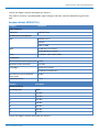
Category Description
Radio Frequency
ISM Bands US902-928 MHz
Certifications and Compliance
EMC US: FCC Part 15 Class B
Canada: ICES-003
Radio FCC 15.247:2015
FCC 15.109:2015
FCC 15.107:2015
Safety UL 60950-1 2nd ED
cUL 60950-1 2nd ED
Transmission
Max Transmitter Power Output (TPO) 19 dBm
Maximum Receive Sensitivity -130 dBm
Link Budget
1
147 dB Point-to-Point
145 dB Point-to-Multipoint
Max Effective Isotropic Radiated
Power (EiRP)
36 dBm
Deep Sleep Current < 2 uA
Category Description
Receive Sensitivity
Spreading Factor North America
2
6 -111 dBm
7 -116 dBm
8 -119 dBm
9 -122 dBm
10 -125 dBm
11 -127 dBm
12 -129 dBm

SPECIFICATIONS AND PIN INFORMATION
xDot
®
Developer Guide 17
1
Greater link budget is possible with higher gain antenna.
2
RFS_L500: RF sensitivity, Long-Range Mode, highest LNA gain, LNA boost, 500 kHz bandwidth using split Rx/Tx
path.
European Models (MTXDOT-EU)
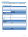
Category Description
Radio Frequency
ISM Bands EU863-870 MHz
Certifications and Compliance
EMC EN55022 Class B
EN55024
CISPR 22:2008
Radio EN 300 220-2 V2.4.1:2012
EN 301 489-03 V1.6.1:2013
Safety IEC 60950-1 2nd ED AM1 & AM2
Transmission
Max Transmitter Power Output (TPO) 14 dBm
Maximum Receive Sensitivity -137 dBm
Link Budget
1
147 dB Point-to-Point
151 dB Point-to-Multipoint
Max Effective Isotropic Radiated
Power (EiRP)
10 dBm
Deep Sleep Current < 2 uA
Category Description
Receive Sensitivity
Spreading Factor EMEA
2
6 -121 dBm
7 -124 dBm
8 -127 dBm
9 -130 dBm
10 -133 dBm
11 -135 dBm
12 -137 dBm
1
Greater link budget is possible with higher gain antenna.

SPECIFICATIONS AND PIN INFORMATION
18 xDot
®
Developer Guide
2
RFS_L125: RF sensitivity, Long-Range Mode, highest LNA gain, LNA boost, 125 kHz bandwidth using split Rx/Tx
path.
Australian Models (MTXDOT-AU1)
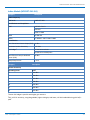
Category Description
Radio Frequency
ISM Bands AU915-928 MHz
Certifications and Compliance
EMC AS/NZS CISPR 22 E
Radio AS/NZS 4268:2012 + a1:2013
MPE Standard 2014
Safety AS/NZS 60950.1:2015
Transmission
Max Transmitter Power Output (TPO) 19 dBm
Maximum Receive Sensitivity -130 dBm
Link Budget
1
147 dB Point-to-Point
145 dB Point-to-Multipoint
Max Effective Isotropic Radiated
Power (EiRP)
36 dBm
Deep Sleep Current < 2 uA
Category Description
Receive Sensitivity
Spreading Factor Australia
2
6 -111 dBm
7 -116 dBm
8 -119 dBm
9 -122 dBm
10 -125 dBm
11 -127 dBm
12 -129 dBm
1
Greater link budget is possible with higher gain antenna.
2
RFS_L500: RF sensitivity, Long-Range Mode, highest LNA gain, LNA boost, 500 kHz bandwidth using split Rx/Tx
path.

SPECIFICATIONS AND PIN INFORMATION
xDot
®
Developer Guide 19
Indian Models (MTXDOT-EU1-IN1)
Category Description
Radio Frequency
ISM Bands IN865-867 MHz
Certifications and Compliance
EMC EN55022 Class B
EN55024
CISPR 22:2008
Radio EN 300 220
Safety IEC 60950-1 2nd ED AM1 & AM2
Transmission
Max Transmitter Power Output (TPO) 14 dBm
Maximum Receive Sensitivity -137 dBm
Link Budget
1
147 dB Point-to-Point
151 dB Point-to-Multipoint
Max Effective Isotropic Radiated
Power (EiRP)
10 dBm
Deep Sleep Current < 2 uA
Category Description
Receive Sensitivity
Spreading Factor India
2
6 -121 dBm
7 -124 dBm
8 -127 dBm
9 -130 dBm
10 -133 dBm
11 -135 dBm
12 -137 dBm
1
Greater link budget is possible with higher gain antenna.
2
RFS_L125: RF sensitivity, Long-Range Mode, highest LNA gain, LNA boost, 125 kHz bandwidth using split Rx/Tx
path.

SPECIFICATIONS AND PIN INFORMATION
20 xDot
®
Developer Guide
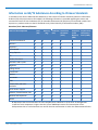
South Korean Models (MTXDOT-KR1)
Category Description
Radio Frequency
ISM Bands KR920-923 MHz
Certifications and Compliance
EMC Pending
Radio Pending
Safety Pending
Transmission
Max Transmitter Power Output (TPO) 19 dBm
Maximum Receive Sensitivity -130 dBm
Link Budget
1
147 dB Point-to-Point
145 dB Point-to-Multipoint
Max Effective Isotropic Radiated
Power (EiRP)
36 dBm
Deep Sleep Current < 2 uA
Category Description
Receive Sensitivity
Spreading Factor South Korea
2
6 -111 dBm
7 -116 dBm
8 -119 dBm
9 -122 dBm
10 -125 dBm
11 -127 dBm
12 -129 dBm
1
Greater link budget is possible with higher gain antenna.
2
RFS_L500: RF sensitivity, Long-Range Mode, highest LNA gain, LNA boost, 500 kHz bandwidth using split Rx/Tx
path.
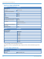
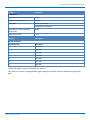
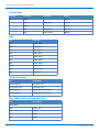
Asia Pacific Models (MTXDOT-AS1)
Category Description
Radio Frequency
ISM Bands AS920-923 MHz (“AS1”)
La page charge ...
La page charge ...
La page charge ...
La page charge ...
La page charge ...
La page charge ...
La page charge ...
La page charge ...
La page charge ...
La page charge ...
La page charge ...
La page charge ...
La page charge ...
La page charge ...
La page charge ...
La page charge ...
La page charge ...
La page charge ...
La page charge ...
La page charge ...
La page charge ...
La page charge ...
La page charge ...
La page charge ...
La page charge ...
La page charge ...
La page charge ...
La page charge ...
La page charge ...
La page charge ...
La page charge ...
La page charge ...
La page charge ...
La page charge ...
La page charge ...
La page charge ...
La page charge ...
La page charge ...
La page charge ...
La page charge ...
La page charge ...
La page charge ...
La page charge ...
La page charge ...
La page charge ...
La page charge ...
La page charge ...
La page charge ...
La page charge ...
La page charge ...
-
 1
1
-
 2
2
-
 3
3
-
 4
4
-
 5
5
-
 6
6
-
 7
7
-
 8
8
-
 9
9
-
 10
10
-
 11
11
-
 12
12
-
 13
13
-
 14
14
-
 15
15
-
 16
16
-
 17
17
-
 18
18
-
 19
19
-
 20
20
-
 21
21
-
 22
22
-
 23
23
-
 24
24
-
 25
25
-
 26
26
-
 27
27
-
 28
28
-
 29
29
-
 30
30
-
 31
31
-
 32
32
-
 33
33
-
 34
34
-
 35
35
-
 36
36
-
 37
37
-
 38
38
-
 39
39
-
 40
40
-
 41
41
-
 42
42
-
 43
43
-
 44
44
-
 45
45
-
 46
46
-
 47
47
-
 48
48
-
 49
49
-
 50
50
-
 51
51
-
 52
52
-
 53
53
-
 54
54
-
 55
55
-
 56
56
-
 57
57
-
 58
58
-
 59
59
-
 60
60
-
 61
61
-
 62
62
-
 63
63
-
 64
64
-
 65
65
-
 66
66
-
 67
67
-
 68
68
-
 69
69
-
 70
70


Multitech MTXDOT-NA1-A00-100 Mode d'emploi
- Taper
- Mode d'emploi
dans d''autres langues
Documents connexes
-
Multitech MultiConnect xDot MTXDOT-NA1-A00 Developer's Manual
-
-
-
-
-
-
-
-
-
Multitech MTQ-MNA1-B01-SP Mode d'emploi
Autres documents
-
Multi-Tech MultiConnect xDot MTXDOT-868 Series Developer's Manual
-
LAB T LavvieBeacon Manuel utilisateur
-
RAK 172 WisDuo LPWAN Module Manuel utilisateur
-
Smart SRSM.ENV-SENSOR.01 Manuel utilisateur
-
Zenner OD2 Manuel utilisateur
-
 KingSmith C-8031U Integrated WiFi and Bluetooth BLE Dual Mode Module Manuel utilisateur
-
Coral Single-Board Computer Mode d'emploi
-
Godox GX-SEKONIC-A Wireless Module Manuel utilisateur
-
Powercast TX91503 Manuel utilisateur
-
COREKINECT NATLRA1 Manuel utilisateur
