Panaonic EY7202 Manuel utilisateur
- Catégorie
- Perceuses mixtes sans fil
- Taper
- Manuel utilisateur
Ce manuel convient également à

Cordless Impact Driver
Perceuse à impact sans fil
Destornillador de impacto inalámbrico
Operating Instructions
Instructions d'utilisation
Manual de instrucciones
Model No : EY7202
IMPORTANT
This manual contains safety information. Read manual completely before first using this product and save this
manual for future use.
IMPORTANT
Ce mode d’emploi contient des informations sur la sécurité. Lisez-le en entier avant d’utiliser le produit et
conservez-le pour référence.
IMPORTANTE
Este manual contiene información de seguridad. Lea completamente este manual antes de utilizar por primera
vez este producto, y guárdelo para poder consultarlo en el futuro.

-
2
-
Index/Index/Indice
English: Page 3
Français: Page 15
Español: Página 29
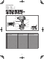
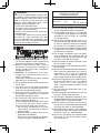
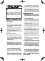
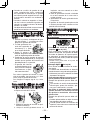
FUNCTIONAL DESCRIPTION
DESCRIPTION DES FONCTIONS
DESCRIPCIÓN FUNCIONAL
Fig. 1
A B
C
D
E
F
G
H
M
N
O
I
JK
L
A
6.35 mm (1/4”) hex quick connect chuck
Mandrin de connexion rapide hexagonal de 6,35 mm (1/4")
Mandril hexagonal de conexión rápida de 6,35 mm (1/4")
B
Nose protector Protection du bec Protector del morro
C
Forward/Reverse lever
Levier d’inversion marche avant/marche arrière
Palanca de avance/marcha atrás
D
Belt hook lock lever
Levier de verrouillage du crochet de ceinture
Palanca de bloqueo del gancho de cinturón
E
Belt hook Crochet de ceinture Gancho del cinturón
F
Battery pack release button Bouton de libération de batterie autonome Botón de liberación de batería
G
Battery pack (EY9201) Batterie autonome (EY9201) Batería (EY9201)
H
Bit holder (inside of the body) Porte-mèche (intérieur du corps)
Soporte de broca (en el interior del cuerpo)
I
Control panel Panneau de commande Panel de control
J
Impact power mode button
Bouton de mode de puissance d'impact Botón de modo de potencia de impacto
K
Digital clutch setting button
Bouton de réglage d’embrayage numérique
Botón de ajuste de embrague digital
L
One-shot impact button
Bouton d'impact à une seule percussion
Botón de impacto de un disparo
M
Variable speed control trigger Gâchette de commande de vitesse
Disparador del control de velocidad variable
N
LED light Lumière DEL Luz indicadora
O
Battery charger (EY0110) Chargeur de batterie (EY0110) Cargador de baterías (EY0110)

-
3
-
I. GENERAL SAFETY
RULES
WARNING! Read all instructions
Failure to follow all instructions listed below
may result in electric shock, fire and/or
serious injury. The term "power tool" in all
of the warnings listed below refers to your
mains operated (corded) power tool and
battery operated (cordless) power tool.
SAVE THESE INSTRUCTIONS
Work Area Safety
1) Keep work area clean and well lit.
Cluttered and dark areas invite accidents.
2)
Do not operate power tools in explosive
atmospheres, such as in the presence
of flammable liquids, gases or dust.
Power tools create sparks which may
ignite the dust or fumes.
3) Keep children and bystanders away
while operating a power tool.
Distractions can cause you to lose control.
Electrical Safety
1) Power tool plugs must match the outlet.
Never modify the plug in any way. Do
not use any adapter plugs with earthed
(grounded) power tools.
Unmodified plugs and matching outlets will
reduce risk of electric shock.
2) Avoid body contact with earthed or
grounded surfaces such as pipes, radi
-
ators, ranges and refrigerators.
There is an increased risk of electric shock
if your body is earthed or grounded.
3) Do not expose power tools to rain or
wet conditions.
Water entering a power tool will increase
the risk of electric shock.
4) Do not abuse the cord. Never use the
cord for carrying, pulling or unplugging
the power tool. Keep cord away from
heat, oil, sharp edges or moving parts.
Damaged or entangled cords increase the
risk of electric shock.
5)
When operating a power tool outdoors, use
an extension cord suitable for outdoor use.
Use of a cord suitable for outdoor use
reduces the risk of electric shock.
Personal safety
1)
Stay alert, watch what you are doing
and use common sense when operating
a power tool. Do not use a power tool
while you are tired or under the influ
-
ence of drugs, alcohol or medication.
A moment of inattention while operating
power tools may result in personal injury.
2) Use safety equipment. Always wear eye
protection.
Safety equipment such as dust mask,
non-skid safety shoes, hard hat, or hear
-
ing protection used for appropriate condi
-
tions will reduce personal injuries.
3)
Avoid accidental starting. Ensure the switch
is in the off position before plugging in.
Carrying power tools with your finger on
the switch or plugging in the power tools
that have the switch on invites accidents.
4) Remove any adjusting key or wrench
before turning the power tool on.
A wrench or a key left attached to a rotat
-
ing part of the power tool may result in
personal injury.
5) Do not overreach. Keep proper footing
and balance at all times.
This enables better control of the power
tool in unexpected situations.
6)
Dress properly. Do not wear loose cloth-
ing or jewellery. Keep your hair, clothing
and gloves away from moving parts.
Loose clothes, jewellery or long hair can
be caught in moving parts.
7) If devices are provided for the connec-
tion of dust extraction and collection
facilities, ensure these are connected
and properly used.
Use of these devices can reduce dust
related hazards.
Power tool use and care
1) Do not force the power tool. Use the
correct power tool for your application.
The correct power tool will do the job better
and safer at the rate for which it was designed.
2) Do not use the power tool if the switch
does not turn it on and off.
Any power tool that cannot be controlled
with the switch is dangerous and must be
repaired.
3) Disconnect the plug from the power
source and/or the battery pack from the
power tool before making any adjust
-
ments, changing accessories, or stor
-
ing power tools.
Such preventive safety measures reduce
the risk of starting the power tool acci
-
dentally.
4) Store idle power tools out of the reach
of children and do not allow persons
unfamiliar with the power tool or these
instructions to operate the power tool.
Power tools are dangerous in the hands of
untrained users.

-
4
-
5)
Maintain power tools. Check for misalign-
ment or binding of moving parts, breakage
of parts and any other condition that may
affect the power tools operation. If damaged,
have the power tool repaired before use.
Many accidents are caused by poorly
maintained power tools.
6) Keep cutting tools sharp and clean.
Properly maintained cutting tools with sharp
cutting edges are less likely to bind and are
easier to control.
7) Use the power tool, accessories and
tool bits etc. in accordance with these
instructions and in the manner intend
-
ed for the particular type of power tool,
taking into account the working condi
-
tions and the work to be performed.
Use of the power tool for operations different
from those intended could result in a haz
-
ardous situation.
Battery tool use and care
1) Ensure the switch is in the off position
before inserting battery pack.
Inserting battery pack into power tools that
have the switch on invites accidents.
2) Recharge only with the charger speci-
fied by the manufacturer.
A charger that is suitable for one type of
battery pack may create a risk of fire when
used with another battery pack.
3) Use power tools only with specifically
designated battery packs.
Use of any other battery packs may create
a risk of injury and fire.
4) When battery pack is not in use, keep it
away from other metal objects like paper
clips, coins, keys, nails, screws, or other
small metal objects that can make a con
-
nection from one terminal to another.
Shorting the battery terminals together
may cause burns, or a fire.
5)
Under abusive conditions, liquid may be
ejected from battery; avoid contact. If contact
accidentally occurs, flush with water. If liquid
contacts eyes, additionally seek medical help.
Liquid ejected from the battery may cause
irritation or burns.
Service
1) Have your power tool serviced by a
qualified repair person using only iden
-
tical replacement parts.
This will ensure that the safety of power
tool is maintained.
WARNING
To reduce the risk of injury, user must
read instruction manual.
II. SPECIFIC SAFETY
RULES
1) Hold tool by insulated gripping sur-
faces when performing an operation
where the cutting tool may contact hid
-
den wiring.
Contact with a “live” wire will make
exposed metal parts of the tool “live”and
shock the operator.
2) Wear ear protectors when using the
tool for extended periods.
Prolonged exposure to high intensity noise
can cause hearing loss.
3)
Be aware that this tool is always in an
operating condition, it does not have to be
plugged into an electrical outlet.
4)
Do not operate the Forward/Reverse
lever when the Variable speed control
trigger is on.
The battery will discharge rapidly and
damage to the unit may occur.
5) If the bit becomes jammed, immediately
turn the Variable speed control trigger
off to prevent an overload which can
damage the battery pack or motor. Use
reverse motion to loosen jammed bits.
6) When storing or carrying the tool, set
the Forward/Reverse lever to the center
(switch lock) position.
7) Do not strain the tool by holding the
speed control trigger halfway (speed
control mode) so that the motor stops.
8)
During charging, the charger may
become slightly warm. This is normal. Do
not charge the battery for a long period.
Symbol Meaning
V
Volts
Direct current
n
0
No load speed
…/min
Revolutions or
reciprocation per minutes
→
(Toward Chuck)
Forward rotation
→
(Toward Motor)
Reverse rotation

-
5
-
WARNING!
Some dust created by power sanding, saw-
ing, grinding, drilling, and other construction
activities contains chemicals known to the
State of California to cause cancer, birth
defects or other reproductive harm. Some
examples of these chemicals are:
• Lead from lead-based paints
• Crystalline silica from bricks and cement
and other masonry products
• Arsenic and chromium from chemically-
treated lumber.
To reduce your exposure to these chemi-
cals: work in a well ventilated area, and
work with approved safety equipment, such
as dust masks that are specially designed
to filter out microscopic particles.
III. FOR
BATTERY CHARGER
& BATTERY PACK
Important Safety Instructions
1) SAVE THESE INSTRUCTIONS
-This man-
ual contains important safety and operating
instructions for battery charger EY0110.
2) Before using battery charger, read all
instructions and cautionary markings on
battery charger, battery pack, and product
using battery pack.
3) CAUTION -
To reduce the risk of injury,
charge only Panasonic Battery Pack as
shown in last page.
Other types of batteries may burst causing
personal injury and damage.
4) Do not expose charger and battery pack to
rain or snow.
5) To reduce risk of damaging the electric
plug and cord, pull by plug rather than
cord when disconnecting charger.
6) Make sure cord is located so that it will not
be stepped on, tripped over, or otherwise
subjected to damage or stress.
7) An extension cord should not be used
unless absolutely necessary.
Use of improper extension cord could result
in a risk of fire and electric shock. If exten
-
sion cord must be used, make sure that:
a.
pins on plug of extension cord are the
same number, size and shape as those of
plug on charger.
b. extension cord is properly wired and in
good electrical condition.
c. wire size is large enough for ampere
rating of charger as specified below.
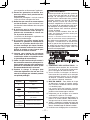
RECOMMENDED MINIMUM AWG SIZE OF
EXTENSION CORDS FOR
BATTERY CHARGERS
AC Input Rating. Amperes
AWG Size of Cord
Equal to or
greater than
But less
than
Length of Cord,
Feet
25 50 100 150
0 2 18 18 18 16
8) Do not operate charger with damaged
cord or plug-replace them immediately.
9) Do not operate charger if it has received
a sharp blow, been dropped, or otherwise
damaged in any way; take it to a qualified
service personnel.
10)Do not disassemble charger; take it to a
qualified service personnel when service
or repair is required. Incorrect reassembly
may result in a risk of electric shock or fire.
11)To reduce the risk of electric shock, unplug
charger from outlet before attempting any
maintenance or cleaning.
12)The charger and battery pack are specif-
ically designed to work together. Do not
attempt to charge any other cordless tool
or battery pack with this charger.
13)Do not attempt to charge the battery pack
with any other charger.
14)Do not attempt to disassemble the battery
pack housing.
15)Do not store the tool and battery pack in loca-
tions where the temperature may reach or
exceed 50°C (122°F) (such as a metal tool
shed, or a car in the summer), which can
lead to deterioration of the storage battery.
16)Do not charge battery pack when the tem-
perature is BELOW 0°C (32°F) or ABOVE
40°C (104°F). This is very important in
order to maintain optimal condition of the
battery pack.
17)Do not incinerate the battery pack. It can
explode in a fire.
18)Avoid dangerous environment. Do not use
charger in damp or wet locations.
19)The charger is designed to operate on stan-
dard household electrical power only. Do not
attempt to use it on any other voltage!
20)Do not abuse cord. Never carry charger by
cord or yank it to disconnect from outlet. Keep
cord away from heat, oil and sharp edges.
21)Charge the battery pack in a well ventilated
place, do not cover the charger and battery
pack with a cloth, etc., while charging.
22)Use of an attachment not recommended
may result in a risk of fire, electric shock,
or personal injury.

-
6
-
23
) Do not short the battery pack. A battery
short can cause a large current flow, over
heating and create the risk of fire or per
-
sonal injury.
24
)
NOTE: If the supply cord of this appliance
is damaged, it must only be replaced by a
repair shop authorized by the manufacturer,
because special purpose tools are required.
25
)
TO REDUCE THE RISK OF ELECTRIC
SHOCK, THIS APPLIANCE HAS A POLAR
-
IZED PLUG (ONE BLADE IS WIDER THAN
THE OTHER).
This plug will fit in a polarized outlet only one
way. If the plug does not fit fully in the outlet,
reverse the plug. If it still does not fit, contact
a qualified electrician to install the proper
outlet. Do not change the plug in any way.
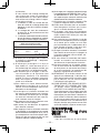
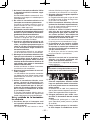
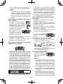
IV. ASSEMBLY
Attaching or removing bit
NOTE:
•
When attaching or removing a bit, discon-
nect battery pack from tool or place the
switch in the center position (switch lock).
1. Hold the collar of quick connect chuck and
pull it against the driver.
2. Insert the bit into the chuck.
3. The collar will return to its original position
when it is released.
4.
Pull the bit to make sure it does not come out.
5. To remove the bit, pull back on the collar
in the same way.
CAUTION:
•
If the collar does not return to its original
position or the bit comes out when pulled on,
the bit has not been properly attached. Make
sure the bit is properly attached before use.
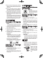
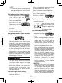
Use 6.35mm (1/4”) hexagonal bits.
To ensure proper securement of the bit, use
only hexagonal bits with 9.5mm (3/8”) detent.
6.35mm (1/4”)
9.5mm (3/8”)
Attaching or removing
battery pack
1. To connect the battery pack:
Insert the battery pack. It snaps into place
to indicate proper connection.
2. To remove the battery pack:
Press the two buttons on the sides of the
battery pack. Slide the battery pack out of
the tool body.
V. OPERATION
Switch and Forward / Reverse
lever Operation
(Forward, Lock, Reverse)
CAUTION:
•
To prevent damage, do not
operate Forward/Reverse
lever until the bit comes to
a complete stop.
Forward Rotation Switch
Operation
1. Push the lever for forward rotation.
2.
Depress the trigger switch slightly to start the
tool slowly.
3. The speed increases with the amount of
depression of the trigger for efficient tight
-
ening of screws. The brake operates and
the bit stops immediately when the trigger
is released.
4. After use, set the lever to its center posi-
tion (switch lock).
Reverse Rotation Switch
Operation
1.
Push the lever for reverse rotation. Check
the
direction of rotation before use.
2.
Depress the trigger switch slightly to start the
tool slowly.
3. After use, set the lever to its center posi-
tion (switch lock).
CAUTION:
• To eliminate excessive temperature
increase of the tool surface, do not oper
-
ate the tool continuously using two or
more battery packs. Tool needs cool off
time before switching to another pack.
LED light
CAUTION:
• The built-in LED light is designed to illu-
minate the small work area temporarily.
• Do not use it as a substitute for a
regular flashlight, since it does not have
enough brightness.
Depress the trigger
switch, then LED
light turns on. When
the trigger switch is
released, the light
turns off automati
-
cally.

-
7
-
The light illuminates with very low cur-
rent, and it does not adversely affect the
performance of the driver during use or its
battery capacity.
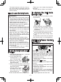
How to use the belt hook
WARNING!
• Be sure to attach the belt hook securely
to the main unit with the screw firmly
fastened. When the belt hook is not firmly
attached to the main unit, the hook may
depart and the main unit may fall.
This may result in an accident or injury.
• Periodically check screw for tightness. If
found to be loose, tighten firmly.
• Be sure to attach the belt hook firmly and
securely onto a waist belt or other belt.
Pay attention to the unit not slipping off
from the belt.
This may result in an accident or injury.
• When the main unit is held by the belt
hook, avoid jumping or running with it.
Doing so may cause the hook to slip and
the main unit may fall.
This may result in an accident or injury.
• When the belt hook is not used, be sure
to return it to the storing position. The belt
hook may catch on something.
This may result in an accident or injury.
• When the unit is hooked onto the waist
belt by the belt hook, do not attach driver
bits to the unit.
A sharp edge object, such as a drill bit,
may cause injury or an accident.
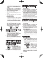
To set the belt hook angle
position
1. Slide the belt hook lock lever 1 and hold
it to unlock the belt hook.
2
1
3
2. Pull the belt hook from
storing position 2 and
set it as desired angle.
3.
Release the belt hook
lock lever to
lock the
angle of belt hook.
4.
Make sure the belt hook is firmly locked
3
. Also make sure the belt hook is firmly
locked into position.
• The belt hook cannot
be locked in this posi-
tion. Firmly lock it into
position before use.
To return the belt hook to the storing position,
Follow step 1. and 2. above, then lower the
belt hook.
To secure the lock, follow 3 and 4 above.
To change the belt hook
location side
The belt hook can be attached to either
side of the unit.
1. Set the belt hook at storing position.
2. Loosen the screw turning it counter-
clockwise, using a coin or a flat blade
screw driver.
3.
Take out the belt hook and insert into the
other side of the slot on the main unit.
4. Fasten the screw firmly, turning it clock-
wise.
The belt hook can be taken out from the
main unit only when it is at storing position.
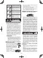
Additional Power Control
Functions
Quick Reference for Features and Functions
AB
C
Impact power mode select:
A
(See p.8.)
→
This unit is equipped with impact power
mode button.By pressing impact power
mode button, soft
impact mode, medium
impact mode and hard impact mode can
be selected (3 settings).
∗
Please use this together with digital
clutch setting.
Digital clutch :
B
(See p.9.)
→
This unit is equipped with the digital clutch
function.
The driver rotation will stop when the set
clutch load is reached.
∗
Please use this together with impact
power mode select.
This digital clutch is not intended for
controlling the accuracy of the fasten-
ing torque.
Example application not to be used;

-
8
-
To control the shut-off torque used to
tighten screws and bolts for manufac-
turing and assembly.
Do not use the digital clutch when
tightening screws with a low tighten-
ing torque into materials, such as thin
plastic.
Example application not to be used;
When tightening screws into lightweight
steel sheet which thickness is 0.8 mm
or less.
When tightening screws into soft surface
materials, such as interior finishing
materials.
One-shot impact function :
C
→
Set the one-shot impact function to
tighten screws slightly to adjust the
screw head flush to the material surface.
Select the clutch setting to match the
application. This is used when readjust
-
ing is continuously required.
The driver automatically rotates approx-
imately half round and stops each time
the trigger switch is depressed. (For bolts,
it stops after approximately 5 impacts.)
Within 1 sec. after the trigger switch is
released once, if it is depressed again,
the one-shot impact function will auto
-
matically operate.
Indication lights on the control panel
The indication lights will go off in the
following cases.
• The driver is not operated for 5 min.
• When the battery is replaced.
Depressing the trigger switch again, then
indication lights go on in the previous
condition.
Main recommended applications
and setting guidelines.(see p.13.)
Be sure to set the impact power mode
and digital clutch to match the material
and screws being used for the application.
Adjust the settings from low to high
while checking them to settle on a final
setting for impact power mode select
and for digital clutch setting.
When driving screws into wood, use
the screws of less than 90 mm long and
avoid knots of wood materials.
∗
One-shot impact function requires the
impact power mode select and digital
clutch settings.
Impact Power Mode Select
Selecting the impact power among 3
modes (Hard, Medium, Soft).
Impact power mode button
Press the impact power mode button to
set it. The mode changes to hard, medium,
or soft each time the button is pressed. To
use automatic mode shifting, press the
button for a period (0.6 sec. or more). It
is recommended that the impact power
mode select be used together with the
digital clutch setting and one-shot impact
function.
The driver is preset to “hard” impact mode
setting when shipped from the manufacturer.
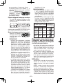
Recommended work guideline table
When maximum power is required in each
impact mode, set the clutch to the “F” mode.
Impact
Power mode
Display
Recommended Application
H
For hard impact power mode.
Fastening long wood screws.
Tightening bolts when install-
ing devices, etc.
Approx.
2,800R.P.M.
(
Max.
)
M
For medium impact power mode.
Fastening small diameter
screws into hard materials.
Driving machine screws when
installing devices.
Approx.
2,500R.P.M.
(
Max.
)
S
For soft impact power mode.
Installing gypsum board.
Installing soft metal window
ame.
Installing interior nishings.
Approx.
2,000R.P.M.
(
Max.
)
One-Shot Impact Function
This function helps adjust the screw head
flush to the material surface.
The driver rotates half round
∗
and auto-
matically stops each time the trigger
switch is depressed while tightening a
screw. The driver will give impact about
5 times and automatically stop while
tightening a bolt even though the trigger
switch is depressed. The one-shot impact
function is also available in reverse rota
-
tion. The impact force is set by the impact
power mode select and digital clutch set
-
tings.

-
9
-
NOTE:
∗ The one-shot impact function operates
after impact. Over-tightening may occur
when tightening screws into soft materi-
als as the tool does not impact.
Using the one-shot impact function
When the trigger switch is released
and it is depressed fully within
1 sec., one-shot impact func-
tion operate. Then
the one-shot
impact LED light will blink.
Wait at least 1 sec. after
trigger is released, not
to operate the one-shot
impact function.
Keeping the bit head to the screw head to use
this function.
When the screw is sticking up quite a ways,
increase the clutch setting.
Using the one-shot impact function
continuously
Refer to the guideline table (See p.13.) and
check the application. Press the impact power
mode button (
) to select the setting. Select
the digital clutch setting (
) that matches the
application. To set the one-shot impact func-
tion, press the button (
) then light (
) turns
on. Depress the trigger switch fully to adjust
the screw tightening until the one-shot impact
function operates. The amount of screw fas-
tening rotation by one-shot impact will differ
depending on the impact power mode and
digital clutch settings. To turn off the one-shot
impact function, press the button (
) once
more then light (
) turns off.
Digital Clutch
The digital clutch automatically stops the
driver rotation when the load is reached
to the select setting. Depress the trigger
switch fully to tighten the screws until the
digital clutch operates. If the screw head
is not flush to the material surface, release
the trigger switch and then within 1 sec.
depress it again. This will operate the one-
shot impact function.
To select digital clutch setting.
Refer to the guideline table and check the
application. (See p.13.)
Press the impact power mode button to set
the impact power mode. (See p.8.)
Press the digital clutch setting buttons and
select the setting to match the application.
The digital clutch setting increases each
time (+) button is pressed.
The setting decreases
each time (
-
) button is
pressed.
Digital clutch setting range
Setting is available from 1 to 16 stages to
match the application.
Full power
Keep pressing the and
button 0.6 sec or more
will automatically shift the
setting to “F”. (Digital clutch
is turned off in the each
impact power mode.)
Turn off the digital clutch.
Press the digital clutch
setting button to change
the setting to “F.”
NOTE:
When selecting the digital clutch set-
ting, first start at a low setting and a soft
impact mode. Then gradually select to
higher settings. Try on a scrap piece of
the material to determine the best set-
ting beforehand. Too high setting could
result in over-tightening of the screws.
Keep the trigger switch fully depressed
while tightening one screw to operate
the digital clutch. Do not release the trig-
ger switch until digital clutch operates.
The clutch setting remains the same
when the driver is changed from for-
ward to reverse rotation while the clutch
is set. To drive in reverse at full power,
change the clutch setting display to “F”
and turn off the digital clutch.
The driver is preset to “F” full power
(digital clutch is off) and the one-shot
impact function is off when shipped
from the manufacture.
CAUTION:
When the clutch is set to 1 or 2 stage, the
impact power mode is automatically set
at “Soft” impact mode regardless of the
impact power mode select display setting.
When the clutch is set to 3 or 4 stage,
the impact power mode is automatically
set at “Medium” impact mode even in
the “Hard” impact mode display setting.

-
10
-
Clutch setting and
operating impact force
Impact
Power Mode
Display
Soft Medium Hard
H
Soft Medium Medium
M
Soft Soft Soft
S
Important remarks when using
the digital clutch and one shot
impact functions
The digital clutch setting could be used
only as a guideline. The suitable setting
will vary depending on the hardness of
the material, the force being applied to the
tool, and the type of screw.
Uneven material hardness could result in
less-tightening or over-tightening depend
-
ing on the position on the material.
If the battery pack capacity is low, the
driver might not fully tighten the screws.
Usage
When driving screws into wood, use the
screws of less than 90 mm long and avoid
knots of wood materials.
Be sure to set the impact power mode
and digital clutch to match the material
and screws being used.
When selecting the digital clutch settings,
start from low to high stage while check
-
ing the setting (on a scrap piece of the
material) to determine the best setting.
Too high setting could result in over-tight
-
ening of the screws.
Depress the trigger switch fully when
using the digital clutch and/or one-shot
impact function during one period of oper
-
ation. Using low speed by trigger switch
could result in a discrepancy in work
results.
When using the digital clutch, depress the
trigger switch fully until the digital clutch
operates. Do not release the switch until
the rotation stops. Releasing the switch
to stop rotation before finishing tighten
-
ing a screw could result in not being fully
tightened. (If this happens, start from the
beginning of fastening.)
Applications not recommended
for these functions
Tightening screws into easily breakable
materials, such as thin plastics.
Tightening screws into lightweight steel
sheet which thickness is 0.8 mm or less.
Tightening TEKS screws into soft surface
materials, such as interior finishing materials.
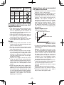
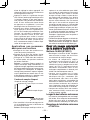
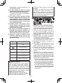
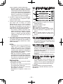
Reason: The impact function is a
mechanical sideway impact. The tight
-
ening torque increases instantly step by
step when the hammer impacts. There
-
fore, fastening torque of impact driver is
not generally increased as a drill driver.
(The accuracy also varies depending on
the material.)
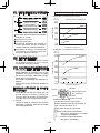
Tightening time
Number of impacts
Impact torque curve
Tightening torque (load)
Drill driver torque increase.
Setting value
Impact torque curve
To control the tightening torque for screws
and bolts during factory manufacturing
and assembly.
Reason: The digital clutch uses a sen-
sor and microcomputer to deduce the load
from the number of motor rotation between
impacts and then stop the rotation when
the load reaches to the set clutch load.
To deduce this load requires at least 4 or
5 impacts, This is not suitable for materi
-
als which requires a low tightening load, as
impact may not occur 4 or 5 times.
The digital clutch cannot operate accurate-
ly when the connecting surface material is
soft and the fixing base sheet is hard.
Example applications for which it cannot
be used;
Attaching gypsum board on hard wood.
Tightening screws with different lengths,
diameters, thread pitches, etc., even if
they are the same type of screw.

-
11
-
For Appropriate use of
Battery pack
Ni-MH Battery pack (EY9201)
• Charge the Ni-MH battery fully before
storage in order to ensure a longer ser
-
vice life.
• The ambient temperature range is
between 0°C (32°F) and 40°C (104°F).
If the battery pack is used when the bat-
tery temperature is below 0°C (32°F), the
tool may fail to function properly. In that
case, charge the battery until charging is
completed for appropriate functioning of
the battery.
• When battery pack is not in use, keep it
away from other metal objects like: paper
clips, coins, keys, nails, screws, or other
small metal objects that can make a con
-
nection from one terminal to another.
Shorting the battery terminals together
may cause sparks, burns or a fire.
• When operating with a Ni-MH battery pack,
make sure the place is well-ventilated.
Battery Pack Life
The rechargeable batteries have a lim-
ited life. If the operation time becomes
extremely short after recharging, replace
the battery pack with a new one.
Battery Recycling
ATTENTION:
FOR Ni-MH Battery Packs, EY9201
A nickel metal hydride battery that is
recyclable powers the product you have
purchased.
Please call 1-800-8-BATTERY for informa
-
tion on how to recycle this battery.
Charging
NOTE:
When you charge the battery pack for
the first time, or after prolonged storage,
charge it for about 24 hours to bring the
battery up to full capacity.
Battery charger (EY0110)
1. Plug the charger into the AC outlet.
NOTE:
Sparks may be produced when the plug
is inserted into the AC power supply, but
this is not a problem in terms of safety.
2.
Insert the battery pack firmly into the charger.
Battery pack
Battery charger
To AC
outlet
3.
During charging, the charging lamp will be lit.
When charging is completed, an internal
electronic switch will automatically be trig
-
gered to prevent overcharging.
• Charging will not start if the battery
pack is warm (for example, immediately
after heavy-duty operation).
The orange standby lamp will be lit until
the battery cools down. Charging will
then begin automatically.
4. When charging is completed, the charg-
ing lamp will start flashing quickly in green
color.
5. When in any of the conditions that battery
pack is too cool, or the battery pack
has not been used for a long time, the
charging lamp is lit. In this case charging
takes longer to fully charge the battery
pack, than the standard charging time.
• If a fully charged battery pack is insert-
ed into the charger again, the charging
lamp lights up. After several minutes,
the charging lamp may flash quickly to
indicate the charging is completed.
6.
If the charging lamp does not light
immedi-
ately after the charger is plugged in, or if
after the standard charging time the lamp
does not go off, consult an authorized
dealer.
NOTE:
• When charging a cool battery pack
(below 5°C (41°F)) in a warm place,
leave the battery pack at the place and
wait for more than one hour to warm up
the battery to the level of the ambient
temperature. Otherwise battery pack
may not be fully charged.
•
Cool down the charger when charging
more than two battery packs consecutively.
• Do not insert your fingers into contact
hole, when holding charger or any other
occasions.

-
12
-
CAUTION:
To prevent the risk of fire or damage to
the battery charger.
• Do not use power source from an
engine generator.
• Do not cover vent holes on the charger
and the battery pack.
• Unplug the charger when not in use.
VI. LAMP INDICATIONS
Red Flashing
Red Lit
Green Flashing quickly
Orange Lit
Orange Flashing
Charger is plugged into the AC outlet.
Ready to charge.
Now charging
Charging is completed.
Battery pack is warm. Charging will begin
when temperature of battery pack drops.
Charging is not possible. Clogged with
dust or malfunction of the battery pack.
VII. MAINTENANCE
Use only a dry, soft cloth for wiping the unit.
Do not use a damp cloth, thinner, benzine,
or other volatile solvents for cleaning.
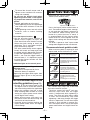
VIII
. TIGHTENING TORQUE
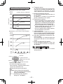
The power required for tightening a bolt
will vary, according to bolt material and
size, as well as the material being bolted.
Choose the length of tightening time
accordingly.
Reference values are provided below.
(They may vary according to tightening conditions.)
Factors Affecting Tightening
Torque
The tightening torque is affected by a wide
variety of factors including the followings.
After tightening, always check the torque
with a torque wrench.
1) Voltage
When the battery pack becomes nearly
discharged, the voltage decreases and the
tightening torque drops.
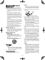
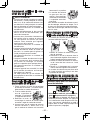
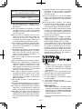
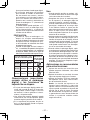
Bolt Tightening Conditions
0.5 1 1.5 2 32.5
M12
M10
M8
Tightening time (Sec.)
Tightening torque
M8.M10.M12 x 25mm Standard bolt
(Bolt size : Millimeters)
N
⋅
m
(kgf-cm)
19.6
(200)
39.2
(400)
58.8
(600)
78.5
(800)
98.1
(1000)
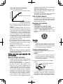
M8.M10.M12 x 25mm High tensile bolt
0.5 1 1.5 2 32.5
M12
M10
M8
Tightening time (Sec.)
Tightening torque
19.6
(200)
39.2
(400)
58.8
(600)
78.5
(800)
98.1
(1000)
117.6
(1200)
N ⋅ m
(k
gf-cm)
Bolt
Nut
Washer
Steel plate
thickness10mm(3/8")
Washer
Spring washer
Tightening conditions
• The following bolts are used.
Standard bolts: Strength type 6.8
High tensile type 12.9
Explanation of the strength type
6.8
Bolt yield point
(80% of tenslie strength)
48
k�f/mm
2
(68,000psi)
Bolt tensile strength 60
k�f/mm
2
(85,000psi)

-
13
-
2) Tightening time
Longer tightening time results in increased
tightening torque. Excessive tightening,
however, adds no value and reduces the
life of the tool.
3) Different bolt diameters
The size of the bolt diameter affects the
tightening torque.
Generally, as the bolt diameter increases,
tightening torque rises.
4) Tightening conditions
Tightening torque will vary, even with the
same bolt, according to grade, length, and
torque coefficient (the fixed coefficient indi-
cated by the manufacturer upon production).
Tightening torque will vary , even with
the same bolting material (e.g. steel),
according to the surface finish.
Torque is greatly reduced when the bolt
and nut start turning together.
5) Socket play
Torque is lowered as the six-sided configu-
ration of the socket of the wrong size is
used to tighten a bolt.
6) Switch (Variable speed control trigger)
Torque is lowered if the unit is used with
the switch not fully pulled out.
7) Effect of Connecting Adaptor
The tightening torque will be lowered
through the use of a universal joint or a
connecting adaptor.
IX. ACCESSORIES
Use only bits suitable for size of chuck.
X. APPENDIX
MAXIMUM RECOMMENDED CAPACITIES
Model
EY7202
Screw
driving
Wood screw
3.5 - 9.5 mm (1/8" - 3/8")
Self-drilling screw
3.5 - 6 mm (1/8" - 1/4")
Bolt fastening
Standard bolt : M6 - M12
High tensile bolt
: M6 - M10
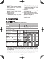
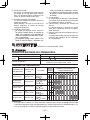
GUIDELINE TABLE
Fixing material
(thickness)
Base material
Screw
(Size)
Impact
power
mode
Clutch setting stage reference
H M S
1 2 3 4 5 6 7 8 9
10 11 12 13 14 15 16
2
4" Material 2
4" Material
Drywall screw
4.2
75
(3/16"
3")
Plywood
12 mm (1/2")
2
4" Material
Drywall screw
3.8
28
(1/8"
1-1/4")
Gypsum board
12 mm (1/2")
2
4" Material
Drywall screw
3.8
28
(1/8"
1-1/4")
SPC
1 2 mm (1/16")
SPC
1 2 mm (1/16")
Self-drilling screw
4
1.3
(3/16"
1/2")
2
4" Material 2
4" Material
Coach screw
9
50
(3/8"
1-15/16")
NOTE:
• When screwing TEKS screws into hard materials, use the lighter digital clutch’s setting to
avoid slippage which may chip or damage the screw. For the final tightening, use the one-
shot impact function.
• Depending on the type of screw or the hardness of the material, the screw may not be com-
pletely flush with the surface. When working with cabinet boards or other more decorative
materials where screws need to sit flush on the surface, use the lighter digital clutch’s setting
to avoid damaging the material, and then finish using the one-shot impact function.

-
14
-
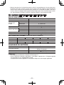
XI. SPECIFICATIONS
MAIN UNIT
Model EY7202
Motor DC Motor 12 V
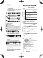
No load speed
soft mode 0 - 2000 /min
mediun mode 0 - 2450 /min
hard mode 0 - 2600 /min
Maximum torque 120 Nm (1220 k
f-cm, 1060 in-lbs.)
Impact per minute
soft mode 0 - 2000 /min
mediun mode 0 - 2500 /min
hard mode 0 - 2800 /min
Overall length 167 mm (6-9/16")
Weight (with battery pack : EY9201) 1.85 k
(4.1 lbs)
BATTERY PACK (EY9201 is included with shipment. )
Model EY9201 EY9200
EY9106, EY9107
EY9101
EY9001, EY9006
Battery voltage 12 V DC (1.2 V × 10 cells)
Storage Battery Ni-MH Battery Ni-Cd Battery
Capacity 3.5 Ah 3.0 Ah 2.0 Ah 1.7 Ah 1.2 Ah
BATTERY CHARGER
Model EY0110
Rating See the rating plate on the bottom of the charger.
Weight 0.78 k
(1.72 lbs)
Charging time 55 minutes (EY9201)
NOTE:
• Do not charge “Y” type Ni-Cd battery packs.
• For applicable battery packs to this charger, see the label on the charger or the latest gen-
eral catalog.
The instruction label on the battery packs also shows the applicable charger.

-
15
-
I.
CONSIGNES DE SÉCU-
RITÉ GÉNÉRALES
AVERTISSEMENT!
Veuillez lire toutes les instructions.
Si les instructions détaillées ci-dessous ne
sont pas observées, cela peut entraîner une
électrocution, un incendie et/ou des blessu-
res graves. Le terme «outil mécanique» utilisé
dans tous les avertissements ci-dessous se
réfère aux outils mécaniques opérés par cor-
dons d’alimentation et par batterie (sans fil).
CONSERVEZ CES INSTRUCTIONS
Sécurité de la zone de travail
1) Gardez la zone de travail propre et bien
aérée.
Les endroits encombrés et sombres invi
-
tent les accidents.
2)
Ne faites pas fonctionner les outils méca-
niques dans des atmosphères explo
-
sives, comme en présence de liquides
inflammables, de gaz ou de poussière.
Les outils mécaniques génèrent des étin-
celles qui peuvent enflammer la poussière
ou les vapeurs.
3) Gardez les enfants et les spectateurs
éloignés lors du fonctionnement d’un
outil mécanique.
Les distractions peuvent faire perdre le
contrôle.
Sécurité électrique
1) La fiche des outils mécanique doit corres-
pondre aux prises secteur. Ne modifiez la
fiche sous aucun prétexte. N’utilisez pas
de fiche adaptatrice avec les outils méca
-
niques mis à la terre.
Des fiches non modifiées et des prises
secteur correspondant réduisent les ris
-
ques d’électrocution.
2) Evitez tout contact physique avec les sur-
faces mises à la terre telles que tuyaux,
radiateurs, micro-ondes et réfrigérateurs.
Il y a un risque d’électrocution supplémen
-
taire si votre corps est mis à la terre.
3) N’exposez pas les outils mécaniques à
la pluie ou à des conditions humides.
De l’eau pénétrant dans un outil mécani
-
que augmente le risque d’électrocution.
4) Ne malmenez pas le cordon. N’utiliser
jamais le cordon pour transporter, pour
tirer ou pour débrancher l’outil méca
-
nique. Gardez le cordon éloigné de la
chaleur, de l’huile, d’objets aux bords
coupants ou de pièces en mouvement.
Les cordons endommagés on emmêlés
augmentent le risque d’électrocution.
5) Lors du fonctionnement des outils méca-
niques à l'extérieur, utilisez une rallonge
adaptée à l'utilisation à l'extérieur.
L’utilisation d’un cordon adapté à l’utilisation
à l’extérieur réduit les risques d’électrocution
Sécurité personnelle
1)
Restez alerte, regardez ce que vous fai-
tes et faites preuve de bon sens lorsque
vous utilisez un outil mécanique. N'uti
-
lisez pas un outil mécanique alors que
vous êtes fatigué ou sous les effets de
drogue, d’alcool ou de médicaments.
Un moment d’inattention pendant que
vous faites fonctionner l’outil mécanique
peut entraîner des blessures graves.
2) Utilisez des équipements de sécurité. Por-
tez toujours des protection pour vos yeux.
Des équipements de sécurité comme
masque antipoussière, chaussures de
sécurité non glissantes, casque de protec
-
tion ou protections d’oreilles, utilisés dans
des conditions appropriées réduisent les
blessures corporelles.
3) Evitez tout démarrage accidentel. Assu-
rez-vous que l’interrupteur est en position
d’arrêt avant de brancher l’outil.
Le transport d’outils mécaniques avec le doigt
sur l’interrupteur ou le branchement d’outils
mécaniques dont l’interrupteur est sur la posi-
tion de marche invite les accidents.
4) Retirez toute clé d'ajustement ou clé de
serrage avant de mettre l'outil mécanique
en marche.
Une clé de serrage ou une clé d’ajuste
-
ment laissée attachée à une pièce tour
-
nante de l’outil mécanique peut entraîner
des blessures corporelles.
5) Ne vous mettez pas en déséquilibre.
Gardez une bonne prise au sol et votre
équilibre à tout moment.
Ceci permet un meilleur contrôle de l’outil
mécanique dans des situations inattendues.
6)
Habillez-vous correctement. Ne portez
pas de vêtements lâches ou de bijoux.
Gardez vos cheveux, vêtements et gants
éloignés des pièces en mouvement.
Des vêtements lâches, des bijoux ou des
cheveux longs peuvent se faire prendre
dans les pièces en mouvement.
7) Si des dispositifs pour la connexion
d'appareils d'extraction et de ramassa
-
ge de la poussière sont fournis, assu
-
rez-vous qu'ils sont connectés et cor
-
rectement utilisés.
L’utilisation de ces dispositifs peut réduire
les risques concernés.

-
16
-
Utilisation et soins de l'outil
mécanique
1) Ne forcez pas l'outil mécanique. Utili-
sez l’outil mécanique correct pour votre
application.
L’outil mécanique correct exécute mieux le tra-
vail dans de meilleurs conditions de sécurité s’il
est utilisé à l’allure pour laquelle il a été conçu.
2) N'utilisez pas l'outil mécanique si l’inter-
rupteur ne le met pas en marche ou ne
l’arrête pas.
Tout outil mécanique qui ne peut pas être
contrôlé par son interrupteur est dange
-
reux et doit être réparé.
3) Débranchez le cordon d’alimentation de
la prise secteur et/ou la batterie autono
-
me de l’outil mécanique avant d’effectuer
des réglages, de changer des accessoi
-
res ou de ranger les outils électriques.
De telles mesures de sécurité préventives
réduisent les risques de faire démarrer
l’outil mécanique accidentellement.
4) Rangez les outils mécaniques inutilisés
hors de la portée des enfants et ne laissez
personne qui n’est pas familiarisé avec
l’outil mécanique ou ses instructions faire
fonctionner l’outil mécanique.
Les outils mécaniques sont dangereux
dans les mains des utilisateurs manquant
d’entraînement.
5) Entretenez bien les outils mécaniques.
Vérifiez l’alignement ou l’emboîtage des
pièces en mouvement, l’intégrité des piè
-
ces et toute autre condition pouvant affec
-
ter le fonctionnement de l’outil mécanique.
S’il est endommagé, faites réparer l’outil
mécanique avant de l’utiliser.
De nombreux accidents sont provoqués
par des outils mécaniques mal entretenus.
6) Maintenez les outils de coupe affûtés et
propres.
Les outils de coupe bien entretenus avec des
lames bien affûtées ont moins de chances de
gripper et sont plus faciles à contrôler.
7) Utilisez l'outil mécanique, les acces-
soires, les mèches, etc., conformément
à ces instructions et de la façon pour
laquelle l’outil particulier a été conçu
en tenant compte des conditions de
travail et de la tâche à exécuter.
L’utilisation de l’outil mécanique à des fins
autres que celles pour lesquelles il a été
conçu peut présenter une situation à risque.
Utilisation et entretien de l'outil
à batterie
1) Avant d'insérer la batterie autonome,
assurez-vous que l’interrupteur d’alimen
-
tation est bien sur la position d’arrêt.
Si vous insérez la batterie autonome dans
des outils électriques dont l’interrupteur d’ali-
mentation est sur la position de marche,
vous risquerez de causer un accident.
2) Effectuez la recharge en utilisant unique-
ment le chargeur spécifié par le fabricant.
Un chargeur convenant à un certain type de
batterie autonome risque de causer un incen
-
die s’il est utilisé avec un autre type de bloc-
batterie.
3) Utilisez les outils électriques unique-
ment avec les batteries autonomes
indiquées spécifiquement.
Si vous utilisez d’autres types de batterie
autonome, vous risquez de vous blesser
ou de causer un incendie.
4) Lorsque vous n'utilisez pas la batte-
rie autonome, gardez-la à distance des
objets métalliques tels que des trombo
-
nes, des pièces de monnaie, des clés, des
clous, des vis et des autres petits objets
métalliques risquant d’établir une con
-
nexion entre les bornes de la batterie.
Si les bornes de la batterie sont court-cir
-
cuitées, vous risquerez de vous brûler ou
de causer un incendie.
5)
En cas de manipulation brutale, de l'électro-
lyte risque d’être éjecté de la batterie; évitez
tout contact avec l’électrolyte. Si un contact
accidentel se produit avec l’électrolyte, rin-
cez abondamment avec de l’eau. Si l’électro
-
lyte entre en contact avec les yeux, consultez
immédiatement un médecin.
L’électrolyte éjecté de la batterie risque de
causer des irritations ou des brûlures.
Réparation
1) Faites réparer votre outil mécanique
par du personnel de réparation qualifié
en n'utilisant que des pièces de rechan
-
ge identiques.
Ceci assure le maintien de la sécurité de
l’outil mécanique.
AVERTISSEMENT
Pour éviter de se blesser, l’utilisateur
doit lire la notice d’utilisation.
II. RÈGLES DE SÉCU-
RITÉ SPÉCIALES
1) Tenez l'outil par les surfaces de prise iso-
lées lorsque vous effectuez une opération
lors de laquelle l’outil de coupe risque d’en
-
trer en contact avec des câblages cachés.
Le contact avec un fil sous tension fera
passer le courant dans les pièces métalli
-

-
17
-
ques exposées et électrocutera l’opérateur.
2) Portez des protections d'oreilles lors-
que vous utilisez l'outil pendant de lon-
gues périodes.
L’exposition prolongée à un bruit intense
risque de causer une perte de l’ouïe.
3) Notez bien que cet outil se trouve toujours
en état de marche, il peut fonctionner sans
être branché nécessairement dans une prise
de courant.
4)
N'actionnez pas le levier d'inversion
marche avant/marche arrière lorsque la
gâchette de commande de vitesse est
sur la position de marche.
La batterie se déchargerait rapidement et
l’outil serait endommagé.
5) Si la mèche se coince, mettez immé-
diatement la gâchette de commande de
vitesse sur la position d'arrêt afin d'évi
-
ter toute surcharge qui risque d’endom-
mager la batterie autonome ou le moteur.
Utilisez la rotation en sens inverse pour
desserrer les mèches coincées.
6) Lorsque vous stockez ou transportez
l’outil, mettez le levier d’inversion marche
avant/marche arrière sur la position centra
-
le (verrouillage de commutateur).
7) Veillez à ce que l’outil ne soit pas soumis à
des contraintes excessives provoquant l’ar-
rêt du moteur parce que vous maintenez la
gâchette de commande de vitesse (mode
de commande de vitesse) à mi-course.
8) Pendant la charge, le chargeur peut
s'échauffer légèrement. Ceci est tout à fait
normal. Ne chargez pas la batterie pendant
une période prolongée
.
Symbole Signication
V
Volts
Courant direct
n
0
Vitesse sans charge
…/min
Rotation ou alternation
par minute
→
(Vers le mandrin)
Rotation en sens normal
→
(Vers le moteur)
Rotation en sens inverse
AVERTISSEMENT:
Certaines particules de poussière produites
lors de travaux de ponçage, de sciage, de
meulage, de fraisage et d’autres travaux
de construction contiennent des produits
chimiques reconnus par l’état de Californie
comme pouvant causer des cancers, des
anomalies congénitales et d’autres anoma-
lies de l’appareil de reproduction. Voici quel-
ques exemples de ces produits chimiques:
• Plomb contenu dans certaines peintures
à base de plomb
• Silicium cristallin contenu dans des bri-
ques, du ciment et certains autres pro-
duits de maçonnerie
• Arsenic et chrome contenus dans certains
bois de construction traités chimiquement
Pour réduire votre exposition à ces produits
chimiques: Travaillez dans un endroit bien
ventilé, et portez des équipements de sécu-
rité agréés tels que des masques antipous-
sière spécialement conçus pour filtrer les
particules microspopiques.
III.
CHARGEUR DE
BATTERIE ET BATTERIE
AUTONOME
Instructions de sécurité impor-
tantes
1) CONSERVEZ CES INSTRUCTIONS - La
présente notice contient des instructions
de sécurité et d’utilisation importantes
pour le chargeur de batterie EY0110.
2) Avant d'utiliser le chargeur de batterie,
lisez toutes les instructions et les marques
d'avertissement figurant sur le chargeur
de batterie, la batterie autonome et le pro-
duit utilisant la batterie autonome.
3) MISE EN GARDE - Pour réduire le risque
de blessures, chargez la batterie autono
-
me Panasonic seulement comme indiqué
à la dernière page.
Les autres types de batteries risquent
d’exploser et de causer des blessures cor-
porelles et des dommages matériels.
4) N’exposez pas le chargeur et la batterie
autonome à la pluie ou à la neige.
5 Pour réduire les risques de dommages à la
fiche et au cordon secteur, débranchez le
chargeur en tirant la fiche et non le cordon.
6) Veillez à acheminer le cordon de façon que
personne ne risque de le piétiner, de trébucher
dessus, d’endommager ou d’étirer le cordon.
7) N’utilisez une rallonge qu’en cas de néces-

-
18
-
sité absolue.
Si vous utilisez une rallonge inadéquate,
vous risquez de causer un incendie ou
une électrocution. Si vous devez absolu-
ment utiliser une rallonge, veillez à respec-
ter les points suivants:
a. Le nombre, la taille et la forme des bro-
ches de la fiche de la rallonge doivent être
identiques à ceux de la fiche du chargeur
de batterie.
b.
La rallonge doit avoir des conducteurs
en bon état et être elle-même en bon
état d’utilisation.
c. La taille des conducteurs doit être suffisan-
te pour les normes d'intensité en ampères
du chargeur, comme indiqué ci-dessous.
TAILLE AWG MINIMUM RECOMMANDEE
DES RALLONGES POUR
CHARGEURS DE BATTERIES
Norme d'entrée CA
Ampères
Taille AWG du cordon
Egal ou supé-
rieur à
Mais infé-
rieur à
Longueur du cordon,
pieds
25 50 100 150
0 2 18 18 18 16
8) N'utilisez pas un chargeur dont la fiche ou
le cordon est endommagé – remplacez-
les immédiatement.
9) N’utilisez pas le chargeur s’il a reçu un
choc violent, s’il a subi une chute ou s’il a
été endommagé de quelque manière que
ce soit; confiez-le à un technicien qualifié.
10)Ne démontez pas le chargeur; si des tra-
vaux d’entretien ou de réparation sont
nécessaires, confiez-le à un technicien
qualifié. Si vous le remontez incorrecte
-
ment, vous risquez de causer une électro
-
cution ou un incendie.
11)Pour réduire le risque d’électrocution,
débranchez le chargeur de la prise de
courant avant d’entreprendre des travaux
d’entretien ou de nettoyage.
12)Le chargeur et la batterie autonome ont
été conçus spécifiquement pour fonction
-
ner ensemble. Ne tentez pas de charger
un autre outil à batterie ou une autre bat-
terie autonome avec ce chargeur.
13)Ne tentez pas de charger la batterie auto-
nome avec un autre chargeur.
14)Ne tentez pas de démonter le logement
de la batterie autonome.
15)Ne rangez pas l’outil ou la batterie autonome
à des endroits où la température est suscep-
tible d’atteindre ou de dépasser 50°C (122°F)
(par exemple dans une remise d’outils élec-
triques, ou dans une voiture en été), car ceci
risquerait d’abîmer la batterie stockée.
16)Ne chargez pas la batterie autonome lorsque
la température est INFERIEURE À 0°C (32°F)
ou SUPERIEURE à 40°C (104°F). Ceci est
très important pour conserver le bon état de
fonctionnement de la batterie autonome.
17)N’incinérez pas la batterie autonome. Elle
risquerait d’exploser dans les flammes.
18)Evitez toute utilisation dans un environne-
ment dangereux. N’utilisez pas le char
-
geur à un endroit humide ou mouillé.
19)Le chargeur a été conçu pour fonctionner
uniquement sur des prises secteur domes-
tiques standard. Ne l’utilisez pas sous des
tensions différentes!
20)Ne manipulez pas brutalement le cordon
secteur. Ne transportez jamais le chargeur
en le tenant par le cordon, ou ne le tirez
pas brutalement pour le débrancher de la
prise. Gardez le cordon à l’abri de la cha-
leur, de l’huile et de bords coupants.
21)Chargez la batterie autonome à un endroit
bien ventilé; ne couvrez pas le chargeur et
la batterie autonome avec un chiffon, etc.,
pendant la charge.
22)Si vous utilisez un accessoire non recom-
mandé, un incendie, une électrocution,
des blessures risqueraient de s’ensuivre.
23)Ne court-circuitez pas la batterie autono-
me. Un court-circuit de la batterie risquerait
de faire passer un courant de forte intensi-
té, et une surchauffe, un incendie ou des
blessures risqueraient de s’ensuivre.
24)REMARQUE: Si le cordon secteur de cet
appareil est endommagé, il doit être rem-
placé exclusivement dans un atelier agréé
par le fabricant, car ces travaux exigent
l’utilisation d’outils spéciaux.
25)POUR REDUIRE LES RISQUES D’ELEC-
TROCUTION, CET APPAREIL EST EQUI-
PE D’UNE FICHE POLARISEE (UNE
LAME EST PLUS LARGE QUE L’AUTRE).
Cette fiche ne pourra être insérée que d’une
seule façon dans une prise polarisée. Si la
fiche ne peut pas être insérée à fond dans la
prise, insérez la fiche sens dessus dessous.
Si vous ne parvenez toujours pas à insérer
la fiche, adressez-vous à un électricien qua
-
lifié pour installer une prise de courant adé
-
quate. Ne modifiez la fiche en aucune façon.
IV. MONTAGE
Fixation ou retrait d’une
mèche
REMARQUE:
•
Lors de la fixation ou du retrait d’une

-
19
-
mèche, déconnectez la batterie autonome
de l’outil ou mettez le commutateur en
position centrale (verrouillage du commu-
tateur).
1. Saisissez le collier du mandrin de con-
nexion rapide et tirez-le contre la perceuse.
2. Insérez la mèche dans le mandrin.
3. Le collier reviendra dans sa position d’ori-
gine lorsqu’il sera relâché.
4.
Tirez sur la mèche pour vérifier qu’elle ne res-
sort pas.
5. Pour retirer une mèche, tirez sur le collier
de la même manière.
MISE EN GARDE:
•
Si le collier ne revient pas dans sa position
d’origine ou si la mèche ressort lorsque vous
tirez dessus, cela signifie que la mèche n’a
pas été fixée correctement. Assurez-vous que
la mèche est bien fixée avant toute utilisation.
Utilisez des mèches hexagonales de
6,35 mm (1/4
"
).
Pour assurer la bonne fixation de la mèche,
utilisez uniquement des mèches hexagonales
possédant une détente de 9,5 mm (3/8").
6,35 mm (1/4")
9,5 mm (3/8")
Fixation ou retrait de la
batterie autonome
1. Pour raccorder la batterie autonome:
Insérez la batterie autonome. Elle s’enclen
-
che une fois en place pour indiquer que le
raccordement a été fait correctement.
2. Pour retirer la batterie autonome:
Appuyez sur les deux boutons qui se trou
-
vent sur les côtés de la batterie autonome.
Faites coulisser la batterie autonome hors
du corps de l’outil.
V. FONCTIONNEMENT
Utilisation du commutateur et
du levier d’inversion marche
avant-marche arrière
(Rotation en sens normal,
Verrouillage, Rotation en
sens inverse)
MISE EN GARDE:
• P
our prévenir tout dégât,
n’actionnez pas le levier
d’inversion marche avant-
marche arrière tant que la
mèche n’a pas complète
-
ment
terminé de tourner.
Utilisation du commutateur pour
une rotation en sens normal
1. Poussez le levier pour obtenir une rotation
en sens normal.
2. Appuyez légèrement sur la gâchette pour
que l’outil commence à tourner lentement.
3. La vitesse augmente en proportion de la force
de pression exercée sur la gâchette et ceci
permet d’effectuer un serrage efficace des vis
et de percer des trous. Le frein entre en action
et la mèche s’arrête de tourner immédiate
-
ment dès que la gâchette est relâchée.
4. Ramenez le levier en position centrale
lorsque vous n’utilisez plus la perceuse
(verrouillage du commutateur).
Utilisation du commutateur
de rotation en sens inverse
1.
Poussez le levier pour obtenir une rotation en
sens inverse. Avant d’utiliser l’outil, vérifiez le
sens de rotation.
2. Appuyez légèrement sur la gâchette pour
que l’outil commence à tourner lentement.
3. Ramenez le levier en position centrale
lorsque vous n’utilisez plus la perceuse
(verrouillage du commutateur).
MISE EN GARDE:
• Pour empêcher toute élévation excessive
de la température de la surface de l'outil,
n'utilisez pas l'outil de façon continue
en utilisant deux batteries autonomes
ou plus. L'outil a besoin de se refroidir
pendant un certain temps avant d'être
connecté à une autre batterie autonome.
Lumière DEL
MISE EN GARDE:
• La lumière DEL intégrée est conçue pour
éclairer temporairement la petite zone de
travail.
• Ne l’utilisez pas pour remplacer une
lampe torche normale car elle n’est pas
assez lumineuse.
Appuyez sur la
gâchette et la DEL
s’allume. Lorsque la
gâchette est relâchée,
la lumière s’éteint
automatiquement.
La lumière éclaire avec une intensité très
faible et n’affecte donc pas de manière
importante les performances du tournevis
pendant l’utilisation ou bien la capacité de
sa batterie.

-
20
-
Comment utiliser le cro-
chet de ceinture
AVERTISSEMENT
• Assurez-vous de bien accrocher le crochet
de ceinture à l’unité principale en serrant
bien la vis. Si le crochet de ceinture n’est
pas bien fixé à l’unité principale, le crochet
peut se décrocher et l’unité peut tomber.
Cela pourrait entraîner un accident ou
des blessures.
• Vérifiez périodiquement le bon serrage
des vis. Si les vis sont desserrées, res-
serrez-les fermement.
• Assurez-vous d’accrocher fermement et
de manière sûre le crochet de ceinture
sur une ceinture de taille ou une autre
ceinture. Faites attention que l’appareil
ne glisse pas de la ceinture.
Cela pourrait entraîner un accident ou
des blessures.
• Lorsque l’unité principale est tenue par le
crochet de ceinture, évitez de sauter ou
de courir. Le crochet pourrait glisser et
l’unité principale pourrait tomber.
Cela pourrait entraîner un accident ou
des blessures.
• Lorsque le crochet de ceinture n’est pas
utilisé, assurez-vous de le remettre dans
sa position de stockage. La ceinture
pourrait se prendre dans quelque chose.
Cela pourrait entraîner un accident ou
des blessures.
• Lorsque l’appareil est accroché à la taille
par le crochet de ceinture, ne fixez pas
de mèches sur l’appareil.
Un objet pointu tel qu’une mèche de
perçage pourrait entraîner un accident ou
des blessures.
Pour régler l’angle de position
du crochet de ceinture
1. Faites coulisser le levier de verrouillage
du crochet de ceinture 1 et tenez-le pour
déverrouiller le crochet de ceinture.
2
1
3
2. Tirez le crochet de cein-
ture de sa position de
stockage 2 et placez-le
à l’angle de votre choix.
3.
Relâchez le levier de
verrouillage du crochet de ceinture pour
verrouiller l’angle du crochet de ceinture.
4.
Assurez-vous que le crochet de ceinture
est bien verrouillé
3
. Veillez aussi à ce
que le crochet de ceinture soit verrouillé
fermement à sa position.
• Le crochet de ceinture
ne peut pas être ver-
rouillé à cette position.
Verrouillez-le fermement
à sa position avant d'uti-
liser l'outil.
Pour remettre le crochet de ceinture en posi-
tion de stockage, effectuez les étapes 1 et 2
ci-avant, puis abaissez le crochet de ceinture.
Pour fixer le verrouillage, effectuez les étapes
3 et 4 ci-avant.
Pour changer le côté d’instal-
lation du crochet de ceinture
Le crochet de ceinture peut être fixé sur
les deux côtés de l’appareil.
1. Mettez le crochet de ceinture en posi-
tion de stockage.
2. Desserrez la vis en la tournant dans le
sens inverse des aiguilles d’une montre, à
l’aide d’une pièce ou d’un tournevis plat.
3.
Retirez le crochet de ceinture et insérez-
le de l’autre côté de la fente sur l’unité
principale.
4. Serrez la vis fermement en la tournant
dans le sens des aiguilles d’une montre.
Le crochet de ceinture ne peut être retiré
de l’unité principale que lorsqu’il est dans
sa position de stockage.
Fonctions de commande de
puissance complémentaires
Référence rapide pour les caractéristi-
ques et les fonctions
AB
C
Sélection du mode de puissance d’im-
pact:
A
(Reportez-vous à la page 21.)
→
Cette perceuse est équipée d’un bouton de
mode de puissance d’impact. En appuyant
sur le bouton de mode de puissance d’im-
pact, vous pouvez sélectionner le mode à
impact doux, le mode à impact moyen et le
mode à impact dur (3 réglages)
La page est en cours de chargement...
La page est en cours de chargement...
La page est en cours de chargement...
La page est en cours de chargement...
La page est en cours de chargement...
La page est en cours de chargement...
La page est en cours de chargement...
La page est en cours de chargement...
La page est en cours de chargement...
La page est en cours de chargement...
La page est en cours de chargement...
La page est en cours de chargement...
La page est en cours de chargement...
La page est en cours de chargement...
La page est en cours de chargement...
La page est en cours de chargement...
La page est en cours de chargement...
La page est en cours de chargement...
La page est en cours de chargement...
La page est en cours de chargement...
La page est en cours de chargement...
La page est en cours de chargement...
La page est en cours de chargement...
La page est en cours de chargement...
-
 1
1
-
 2
2
-
 3
3
-
 4
4
-
 5
5
-
 6
6
-
 7
7
-
 8
8
-
 9
9
-
 10
10
-
 11
11
-
 12
12
-
 13
13
-
 14
14
-
 15
15
-
 16
16
-
 17
17
-
 18
18
-
 19
19
-
 20
20
-
 21
21
-
 22
22
-
 23
23
-
 24
24
-
 25
25
-
 26
26
-
 27
27
-
 28
28
-
 29
29
-
 30
30
-
 31
31
-
 32
32
-
 33
33
-
 34
34
-
 35
35
-
 36
36
-
 37
37
-
 38
38
-
 39
39
-
 40
40
-
 41
41
-
 42
42
-
 43
43
-
 44
44


Panaonic EY7202 Manuel utilisateur
- Catégorie
- Perceuses mixtes sans fil
- Taper
- Manuel utilisateur
- Ce manuel convient également à
dans d''autres langues
- English: Panaonic EY7202 User manual
- español: Panaonic EY7202 Manual de usuario
Autres documents
-
Panasonic EY 7271 Manuel utilisateur
-
-
-
-
-
-
-
Panasonic EY74A1X Manuel utilisateur
-
-