
USER MANUAL - EN
BEDIENUNGSANLEITUNG - DE
NOTICE D’UTILISATION - FR
MODELS - ULTF 40 VTS098 VTS252 VTS254 VTS256 VTS258
BIOMEDICAL SOLUTIONS
FREEZERS
GEFRIERGERÄTE
CONGÉLATEURS


Vestfrost Solutions 3
EN
CONTENTS
WARNING � � � � � � � � � � � � � � � � � � � � � � � � � � � � � � � � � � � � � � � � 4
PRODUCT DESCRIPTION � � � � � � � � � � � � � � � � � � � � � � � � � � � � � � � 7
Before use . . . . . . . . . . . . . . . . . . . . . . . . . . . . . . . . . . 7
Electrical connection . . . . . . . . . . . . . . . . . . . . . . . . . . . . . 8
Intended use . . . . . . . . . . . . . . . . . . . . . . . . . . . . . . . . . 9
Room climate classes . . . . . . . . . . . . . . . . . . . . . . . . . . . . 9
FREEZER COMPONENTS � � � � � � � � � � � � � � � � � � � � � � � � � � � � � � 10
Front & internal view . . . . . . . . . . . . . . . . . . . . . . . . . . . . 10
Backview . . . . . . . . . . . . . . . . . . . . . . . . . . . . . . . . . . 11
Sensor placement . . . . . . . . . . . . . . . . . . . . . . . . . . . . . 12
Display components . . . . . . . . . . . . . . . . . . . . . . . . . . . . 13
INSTALLATION AND START-UP � � � � � � � � � � � � � � � � � � � � � � � � � � � 15
Ventilation guards . . . . . . . . . . . . . . . . . . . . . . . . . . . . . 15
Battery backup . . . . . . . . . . . . . . . . . . . . . . . . . . . . . . . 16
Location and ventiltation . . . . . . . . . . . . . . . . . . . . . . . . . . 17
Levelling the appliance . . . . . . . . . . . . . . . . . . . . . . . . . . 18
Porthole . . . . . . . . . . . . . . . . . . . . . . . . . . . . . . . . . . 19
Remote alarm function . . . . . . . . . . . . . . . . . . . . . . . . . . 21
INTERIOR FITTING � � � � � � � � � � � � � � � � � � � � � � � � � � � � � � � � � � 22
CONTROLLER- OPERATION AND FUNCTION � � � � � � � � � � � � � � � � � � � 23
Models VTS252/254/256/258 . . . . . . . . . . . . . . . . . . . . . . . 23
Models VTS098-ULTF040 . . . . . . . . . . . . . . . . . . . . . . . . . 29
MAINTENANCE � � � � � � � � � � � � � � � � � � � � � � � � � � � � � � � � � � � 30
GENERAL INFORMATION � � � � � � � � � � � � � � � � � � � � � � � � � � � � � � 31
Warranty, spare parts and service . . . . . . . . . . . . . . . . . . . . . 31
DISPOSAL � � � � � � � � � � � � � � � � � � � � � � � � � � � � � � � � � � � � � � � 32

4 Vestfrostsolutions.com
EN
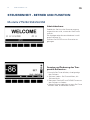
WARNING
As the appliance contains a flammable refrigerant, it is essential
to ensure that the refrigerant pipes are not damaged.
The quantity and type of the refrigerant used in your appli-
ance is indicated on the rating plate�
Standard EN378 specifies that the room in which you install your
appliance must have a volume of 1m³ per 8 g of hydrocarbon
refrigerant used in the appliances. This is to avoid the formation
of flammable gas/air mixtures in the room where the appliance is
located in the event of a leak in the refrigerant circuit.
WARNING:
Keep ventilation openings in the appliance’s cabinet or in the
built-in structure clear of obstruction.
WARNING:
Do not use other mechanical devices or other means to accel-
erate the defrosting process than those recommended by the
manufacturer.
WARNING:
Do not damage the refrigerant system.
WARNING:
Do not use electrical appliances inside the refrigerated storage
compartment, unless they are of a type recommended by the
manufacturer.
WARNING:
Do not expose the appliance to rain, and secure not splashing
water when cleaning the floor.
WARNING:
This appliance can be used by children aged from 8 years and
above and persons with reduced physical, sensory or mental ca-
pabilities or lack of experience and knowledge if they have been

Vestfrost Solutions 5
EN
given supervision or instruction concerning use of the appliance
in a safe way and understand the hazards involved.
WARNING:
Children shall not play with the appliance.
WARNING:
Cleaning and user maintenance shall not be made by children
without supervision.
WARNING:
Do not store explosives, such as aerosol cans with flammable
propellants in the unit.
WARNING:
Danger risk of fire or explosion if flammable refrigerant are used.
To be repaired only by trained personnel.
WARNING:
When positioning the appliance, ensure the power cord is not
trapped or damaged.
WARNING:
Do not locate multiple portable socket-outlets or portable power
supplies at the rear of the appliance.
WARNING:
Sharp edges on cabinet, compressor compartment, evaporator,
ventilation cover and on internal equipment can occur. Please be
aware to avoid injury.
WARNING:
The condenser on the back of the appliance will in some cases
have a hot surface. Please be aware to avoid injury.

6 Vestfrostsolutions.com
EN
WARNING:
The appliance must be connected to power minimum 12 hours
before using it for storage of medicine.
● Always keep the keys in a separate place and out of reach of chil-
dren.
● Do not step on the lower panel to reach medicine in the top of the
appliance.
● Before servicing or cleaning the appliance, unplug the appliance
from the mains or disconnect the electrical power supply.
● If the supply cord is damaged, it must be replaced by the manu-
facturer, its service agent, or similarly qualified persons in order to
avoid a hazard.
● Relevant for Australia: Supply cord fitted with a plug complies
with AS/NZS 3112.
● Frost formation on the interior evaporator wall and upper parts is a
natural phenomenon. Therefore, the appliance should be defrosted
during normal cleaning or maintenance.
● Please note that changes to the appliance construction will cancel
all warranty and product liability.
● This device is intended to be used exclusively for medical pro-
ducts.
● If medicine is spilled in the appliance or the defrost water canal is
has to be cleaned immediately to avoid the medicine to evaporate
to the surroundings.
● If the instructions is lost please contact your supplier of the appli-
ance to have a new instruction for use.
● If service needed to this device, please be aware of only using
service personnel with education in handling medical devices.

Vestfrost Solutions 7
EN
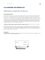
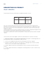
Before use
This user manual is intended for the following product models:
We recommend that you read this user manual before using the unit for the first time. Vestfrost
Solutions does not guarantee safe operation if the unit is used for anything other than its intended
use. Contents of the user manual can be subject to change without notice.
This manual should be considered an integral part of the unit and should be stored close to the
unit and be easy to access.
For current versions of the manual, please visit https://www.vestfrostsolutions.com/biomedical/.
Before operating your new appliance, please read the following instructions carefully:
1. Check to ensure the appliance has not been damaged during transport. Transport damage
should be reported to the transporter delivery.
2. The foil on the shelves must be removed before cleaning and using the unit.
3. Clean the inside of the cabinet using warm water with a mild detergent. Use a soft cloth and
rinse with clean water and dry thoroughly.
4. Allow the freezer to stay at an upright position for at least one hour before switched on.
5. Allow the freezer to operate at the desired temperature for a minimum of 12 hours before
loading.
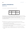
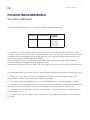
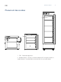
PRODUCT DESCRIPTION
Tabletop Undercounter Upright
ULTF 40 VTS 098 VTS 252
VTS 254
VTS 256
VTS 258

8 Vestfrostsolutions.com
EN
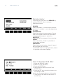
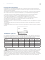
Electrical connection
Wiring and connections in power supply systems must been all applicable (local and national)
electrical codes. Consult these codes lengths and sizes prior to cabinet installation.
This device complies with relevant EU directives including Low Voltage Directive 2014/35/EU and
Electromagnetic Compatibility Directive 2014/30/EU
The socket should be freely accessible.
Connect the appliance only to 220/240V / 50Hz alternating current via a correctly installed earthed
socket.
The socket must be fused with a 10A or 13A fuse.
If the appliance is to be operated in a non-European country, check on the rating plate whether
the indicated voltage and current type correspond to the values of your mains supply.
Data regarding voltage and obsorbed power / current are given on the rating plate.
The power cord may be replaced by a technician only.
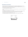
The rating plate provides various technical information as well as type and serial number.
Product number

Vestfrost Solutions 9
EN
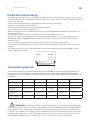
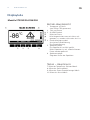
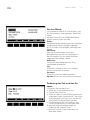
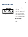
Intended use
Vestfrost biomedical freezers are designed to provide reliable temperature stability and precision
and ensure an ideal cold temperature storage for sensitive items is achieved. The products are
designed for the following operating ranges:
WARNING: This unit is not a “rapid-freeze” device. Freezing large quantities of liquid,
or high-water content items, will temporarily increase the chamber temperature and will cause
the compressors to operate for a prolonged time period. Avoid opening the door for extended
time periods since chamber temperature air will escape rapidly. Also, keep the inner doors closed
as much as possible. When room air, which is higher in humidity, replaces chamber air, frost may
develop in the chamber more rapidly.
Models ULTF40/ VTS098 VTS252 VTS254 VTS256 VTS258
Temperature range -60°C to -86°C -15°C to -30°C -25°C to -45°C -40°C to -60°C -60°C to -86°C
Fabric Set Point -82°C -25°C -45°C -61°C -82°C
Ambient Temperature +16ºC to +32ºC +16ºC to +32ºC +16ºC to+ 32ºC +16ºC to +32ºC +16ºC to +32ºC
Relative humidity MAX 70 % MAX 70 % MAX 70 % MAX 70 % MAX 70 %
Number of probes 1 1 1 1 1
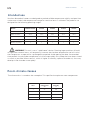
Room climate classes
Room climate
class
Max room
temperature
°C
Relative
humidity
%
3 25 60
4 30 55
5 40 40
7 35 75
The climate class is stated on the nameplate. This specifies the optimum room temperature.

10 Vestfrostsolutions.com
EN
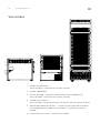
FREEZER COMPONENTS
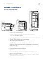
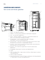
Front & internal view
1. Display – With integrated keyboard
2. USB port – Export historical data. See chapter Display components
3. Light – Only when door is opened
4. Lock – Push and turn lock. ´´Insert the key into the keyhole and push and turn the
key 180 degrees clockwise´´.
5. Porthole – Hole for external sensor and CO² backup.
See chapter Installation and Start-up
6. Vacuum release – Ensure the door opens easily.
IMPORTANT makesure its free of ice. See chapter Maintenance
7. Inner doors – Make sure to close correctly to prevent cold air from escaping
(Is only on VTS 258)
8. Door contact – Can be both a magnetic or mechanical contact.
9. Shelf. See chapter Installation and Start-up
10. Door handle
11. Feet / Adjustable feet – some have antislip. See installation and start-up
12. Wheels – With or without breaks
13. Battery backup button – It will take 10 days for the battery to be fully charged.
See chapter Installation and Start-up
9
4
1
2
8
9
6
10
7
12
11
10
5
3
3
2
9
10
4
11
1
4
2
6
3
8
5
1
8
13

Vestfrost Solutions 11
EN
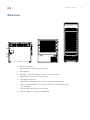
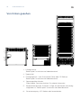
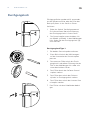
Backview
1. Ventilation guards.
See chapter Installation and Start-up.
2. Rating plate.
3. Porthole – Hole for external sensor and CO2 backup.
See chapter Installation and Start-up
4. Voltage free contact.
See chapter Remote alarm function for more information.
5. Battery backup button – It will take 10 days for the battery to be
fully charged.
See chapter Installation and Start-up
6. Power supply – IEC plug or hardwired.
1
2
6
4
5
3

12 Vestfrostsolutions.com
EN
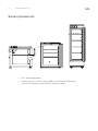
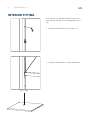
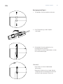
Sensor placement
1. TR3 – Regulating probe.
2. External sensor – Use a 3.5mm cable tie to mounting for external
sensor. The cable tie can be found in the plastic bag.
2
1
1
1

Vestfrost Solutions 13
EN
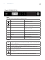
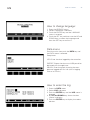
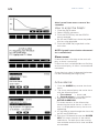
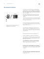
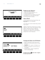
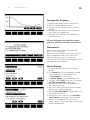
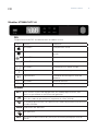
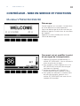
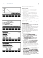
Display components
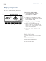
Operation – main view:
1. The temperature in the appliance
(measured by the TR3 probe)
2. Time and date
3. ALARM icon. Flashing by alarm turned
on when there has been an alarm, but the
alarm is no longer active.
4. Logging icon. Turned Off if no logging.
Turned On when logging.
5. Memory icon. Turned On when the
memory is 90% full. Flashing when the
memory is full, and the controller is delet-
ing the oldest logging data.
6. Memory bar. Shows the status of the
memory.
Keys – main view:
7. Enter the Set Point menu of the tempera-
ture.
8. Enter the Service menu.
9. Enter the Data Logging menu.
10. Enter the Alarm menu.
Models VTS252/254/256/258
(7)
(8) (9) (10)

14 Vestfrostsolutions.com
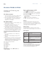
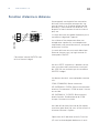
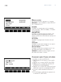
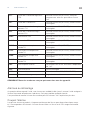
EN
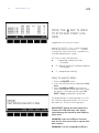
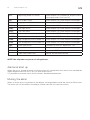
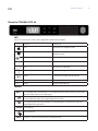
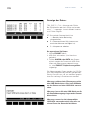
LEDS
Each LED function is described in the following table.
LED MODE Function
ON Compressor enabled
Flashing Anti-short cycle delay enabled
ON An alarm is occurring
ON Recording activated
ON Battery status OK
Flashing Battery is beeing charged
Flashing Charging problem or battery failure
°C/°F ON Measurement unit
°C/°F Flashing Programming phase
Buttons
SET
To display target set point in programming mode it selects a parameter og
confirm an operation.
(UP) To enter fast access menu In programming mode it browses the
parameter codes or increases the displayed value.
(DOWN) In programming mode it browses the parameter codes or de-
creases the displayed value.
DATA
Export data from button.
Not relevant.
REC
Log activation and deactivation from button (Password protected).
Models VTS098/ULTF 40

Vestfrost Solutions 15
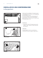
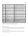
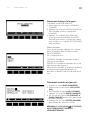
EN
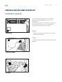
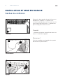
The two ventilation guards are mounted
before moving the appliance to it’s final
placement.
The guards function is to secure an absolute
minimum of ventilation, if the appliance is
pushed too close up against a wall.
Steps:
1. Mount the ventilation guards in the holes
behind the device.
Note!
(Some models have pre mounted ventilations
guards)
Undercounter
Upright
INSTALLATION AND START-UP
Ventilation guards
Tabeltop

16 Vestfrostsolutions.com
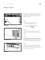
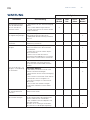
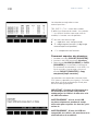
EN
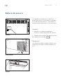
The appliance is equipped with a battery back
up system, which supplies the controller with
power at power failure. The back up system
duration is 48 hours.
Steps:
1. Push the orange button to switch
on the battery backup system.
2. Check if the display for the battery
status-LED is ON
Note!
When starting up the appliance for the first
time it is necessary to charge the battery for
10 days.
Note!
The battery backup system does not supply
the cooling system with power. When starting
up the appliance for the first time it is neces-
sary to switch on the battery backup system.
Note!
The battery for backup should be changed
every third year to secure 48 hours of back
up. Please put this change in the maintenance
schedule for every third year.
Battery backup
Tabeltop
Undercounter
Upright

Vestfrost Solutions 17
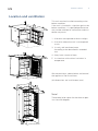
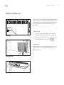
EN
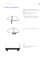
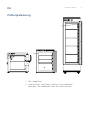
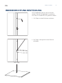
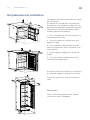
This unit must be installed according to the
below condition:
If the unit is installed in a location against the
below conditions, it’s specified performance
may not be achieved or malfunction and acci-
dence may occur.
1. A location not exposed to direct sunlight
2. A location where the unit is not exposed
to rain
3. In a dry, well ventilated room
According to the described in Intended
use
4. Away from sources of heat
5. In a location with minimal variations in
temperature
Secure ventilation, above, below and around
the appliance. See illustrations.
(All dimensions are in millimeter (mm).
Note!
There need to be space for the door to open
in at least 90 degrees.
Location and ventiltation

18 Vestfrostsolutions.com
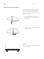
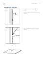
EN
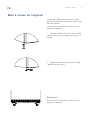
Make sure the appliance is level. It can be
levelled by rotating the adjustable feet of the
appliance.
Be certain to lock the breaks for units
equipped with casters.
1. For some models the ‘’antislip base’’
from the plastic bag and mount it on the
foot.
2. Adjust the four feet´until the unit is lev-
el.
Note!
Be certain to lock the breaks for units
equipped with casters.
Levelling the appliance

Vestfrost Solutions 19
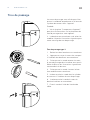
EN
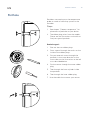
Portholes are used to pass the temperature
probe or nozzle of a back-up system in the
chamber.
Steps:
1. See chapter ´´Freezer components´´ for
placement of porthole on your device.
2. The rubber plug varies from the models.
Please see the illustrations to the left to
find your type of porthole.
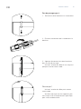
Porthole type 1:
1. Take out the two rubber plugs.
2. Press a pencil through the marks on the
inside of the rubber plugs.
3. Put your external sensor through the
porthole, in the same direction as the
arrow seen on the illustrations to the left
or as described below.
4. Put the sensor through the outer rubber
plug.
5. Then through the foam cylinder inside
the porthole.
6. Then through the inner rubber plug.
7. Use the cable tie to mount your sensor.
Porthole

20 Vestfrostsolutions.com
EN
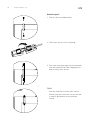
Porthole type 2:
1. Take out the two rubber plugs.
2. Place your sensor wire in the plug.
3. Press the two plugs tight into the porthole
Use the cable tie from the helping plastic
bag to mount your sensor.
Note!
Use the cable tie to mount your sensor.
Please note that some units may not have
a specific placement to your external
sensor.
La page est en cours de chargement...
La page est en cours de chargement...
La page est en cours de chargement...
La page est en cours de chargement...
La page est en cours de chargement...
La page est en cours de chargement...
La page est en cours de chargement...
La page est en cours de chargement...
La page est en cours de chargement...
La page est en cours de chargement...
La page est en cours de chargement...
La page est en cours de chargement...
La page est en cours de chargement...
La page est en cours de chargement...
La page est en cours de chargement...
La page est en cours de chargement...
La page est en cours de chargement...
La page est en cours de chargement...
La page est en cours de chargement...
La page est en cours de chargement...
La page est en cours de chargement...
La page est en cours de chargement...
La page est en cours de chargement...
La page est en cours de chargement...
La page est en cours de chargement...
La page est en cours de chargement...
La page est en cours de chargement...
La page est en cours de chargement...
La page est en cours de chargement...
La page est en cours de chargement...
La page est en cours de chargement...
La page est en cours de chargement...
La page est en cours de chargement...
La page est en cours de chargement...
La page est en cours de chargement...
La page est en cours de chargement...
La page est en cours de chargement...
La page est en cours de chargement...
La page est en cours de chargement...
La page est en cours de chargement...
La page est en cours de chargement...
La page est en cours de chargement...
La page est en cours de chargement...
La page est en cours de chargement...
La page est en cours de chargement...
La page est en cours de chargement...
La page est en cours de chargement...
La page est en cours de chargement...
La page est en cours de chargement...
La page est en cours de chargement...
La page est en cours de chargement...
La page est en cours de chargement...
La page est en cours de chargement...
La page est en cours de chargement...
La page est en cours de chargement...
La page est en cours de chargement...
La page est en cours de chargement...
La page est en cours de chargement...
La page est en cours de chargement...
La page est en cours de chargement...
La page est en cours de chargement...
La page est en cours de chargement...
La page est en cours de chargement...
La page est en cours de chargement...
La page est en cours de chargement...
La page est en cours de chargement...
La page est en cours de chargement...
La page est en cours de chargement...
La page est en cours de chargement...
La page est en cours de chargement...
La page est en cours de chargement...
La page est en cours de chargement...
La page est en cours de chargement...
La page est en cours de chargement...
La page est en cours de chargement...
La page est en cours de chargement...
La page est en cours de chargement...
La page est en cours de chargement...
La page est en cours de chargement...
La page est en cours de chargement...
-
 1
1
-
 2
2
-
 3
3
-
 4
4
-
 5
5
-
 6
6
-
 7
7
-
 8
8
-
 9
9
-
 10
10
-
 11
11
-
 12
12
-
 13
13
-
 14
14
-
 15
15
-
 16
16
-
 17
17
-
 18
18
-
 19
19
-
 20
20
-
 21
21
-
 22
22
-
 23
23
-
 24
24
-
 25
25
-
 26
26
-
 27
27
-
 28
28
-
 29
29
-
 30
30
-
 31
31
-
 32
32
-
 33
33
-
 34
34
-
 35
35
-
 36
36
-
 37
37
-
 38
38
-
 39
39
-
 40
40
-
 41
41
-
 42
42
-
 43
43
-
 44
44
-
 45
45
-
 46
46
-
 47
47
-
 48
48
-
 49
49
-
 50
50
-
 51
51
-
 52
52
-
 53
53
-
 54
54
-
 55
55
-
 56
56
-
 57
57
-
 58
58
-
 59
59
-
 60
60
-
 61
61
-
 62
62
-
 63
63
-
 64
64
-
 65
65
-
 66
66
-
 67
67
-
 68
68
-
 69
69
-
 70
70
-
 71
71
-
 72
72
-
 73
73
-
 74
74
-
 75
75
-
 76
76
-
 77
77
-
 78
78
-
 79
79
-
 80
80
-
 81
81
-
 82
82
-
 83
83
-
 84
84
-
 85
85
-
 86
86
-
 87
87
-
 88
88
-
 89
89
-
 90
90
-
 91
91
-
 92
92
-
 93
93
-
 94
94
-
 95
95
-
 96
96
-
 97
97
-
 98
98
-
 99
99
-
 100
100


Vestfrost VTS252 Manuel utilisateur
- Taper
- Manuel utilisateur
dans d''autres langues
- English: Vestfrost VTS252 User manual
- Deutsch: Vestfrost VTS252 Benutzerhandbuch
Documents connexes
-
Vestfrost AKS 157 Instructions For Use Manual
-
Vestfrost AKG 397 Instructions For Use Manual
-
-
-
-
Autres documents
-
Malaguti SPIDER MAX 500 Diagnostic Manual
-
 Powerplay TR340HX45RSVMQC Information produit
-
Electrolux MR305C Manuel utilisateur
-
 Hach AS950 AWRS Basic Operations
-
Alpha XM3.1-HP Broadband UPS Technical Manual
-
Pego PLUSR EXPERT DL3 Use and Maintenance Manual
-
 Ion Science Tiger LT handheld VOC detector Manuel utilisateur


