MULTIPLEX Picoswitch Le manuel du propriétaire
- Catégorie
- Jouets télécommandés
- Taper
- Le manuel du propriétaire

Switch
TECHNISCHE DATEN
Dauerstrom 10 A
Kurzzeitstrom (<5 min) 12 A
Anzahl NC-Zellen 6 - 12
BEC 5 V, 2 Standard-Servos
Abmessungen ~ 37 x 35 x 14 mm
Gewicht ~ 13,5 g
BESONDERE EIGENSCHAFTEN
··
··
· FET (Feld-Effekt-Transistor) als Schalter
··
··
· BEC-Spannung schaltbar
··
··
· Motoranschlüsse geschraubt
··
··
· Schaltpunkt einstellbar
SICHERHEITSHINWEISE
Anleitung lesen!
Lesen sie diese Anleitung sorgfältig durch, bevor Sie
den Schalter in Betrieb nehmen.
!
Wärmestau vermeiden:
Packen Sie den Schalter nicht in Schaumgummi
ein und meiden Sie die Nähe anderer Wärme-
quellen im Modell (Akku, Motor).
!
Achtung:
Falsch gepolte Akkuanschlußkabel zerstören
den Schalter sofort!
Rotes Kabel an den PLUS-Pol,
schwarzes Kabel an den MINUS-Pol.
Wenn Sie löten müssen: Akku abtrennen!
!
Beim Probebetrieb beachten:
Motor (oder Modell) sicher befestigen. Wenn die
Luftschraube bereits montiert ist: Prüfen, ob
ausreichend Platz zum Ausklappen/Drehen
vorhanden ist. Gegenstände, die angesaugt oder
weggeblasen werden können (Kleidungsstücke,
Kleinteile, Papier, usw.) aus der Nähe der Luft-
schraube entfernen.
ANSCHLIESSEN
l
Motor (möglichst ohne Luftschraube) an die
Schraubklemmen anschließen, BEC-Schalter
in Stellung OFF (Aus) bringen.
l
Gasknüppel in Leerlaufstellung bringen und
Sender einschalten
l
Antriebsakku anschließen, BEC-Schalter ON
Wenn Sie so vorgehen, ist auch sichergestellt, daß der
Motor beim Einschalten nicht ungewollt losläuft.
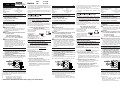
SCHALTPUNKT EINSTELLEN
Bei der Endkontrolle wird die Schaltschwelle auf ca.
1,7 ms eingestellt. Kürzere Impulse schalten den Motor
ein, längere aus. Wenn Sie den Schalter mit dem
Gasknüppel steuern bedeutet das z.B. für einen Sender
vom Typ PiCO-line:
Knüppel vorn = Leerlauf = Motor aus
Knüppel hinten = Vollgas = Motor ein
Schaltpunkt bei ca. 65% Knüppelweg
MULTIPLEX
Modelltechnik GmbH, Neuer Weg 15, D-75223 Niefern
PiCO-line Switch 82 5502
MPX # 7 2258
UNI # 7 2259
Den Schaltpunkt können Sie bei Bedarf im Bereich von
ca. 40% bis 80% des Knüppelweges verschieben. Ver-
stellen Sie dazu das Potentiometer P mit einem kleinen
Kreuzschlitzschraubendreher.
Leerlauf- und Vollgas-Stellung lassen sich vertauschen,
wenn Sie den entsprechenden Servo-Kanal am Sender
umpolen.
BEC = Battery Eliminating Circuit
Empfängerstromversorgung
aus dem Antriebsakku
BEC heißt: Der Empfänger und die Servos werden aus
dem Antriebsakku mit Strom versorgt. Im Modell dürfen
Sie daher
keinen zusätzlichen Empfängerakku an-
schließen. Auch das sonst übliche Schalterkabel ist
nicht nötig, wenn Sie BEC nutzen.
Beachten Sie jedoch, daß die BEC-Versorgung nur
800 mA Strom für die Empfangsanlage im Modell abge-
ben kann. Für die Praxis bedeutet das:
Sie dürfen maximal 2 Standardservos an den
Empfänger anschließen!
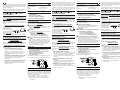
Wenn in Ihrem Modell mehr Servos vorhanden sind,
müssen Sie die BEC-
Versorgung unter-
brechen und einen
zusätzlichen
Empfängerakku einbauen.
Am Empfängeranschluß-
kabel des Reglers muß dazu
der
rote Draht unterbrochen werden.
WICHTIG (NICHT NUR) BEI BEC-BETRIEB!
Wenn die Drehzahl deutlich abnimmt:
Akku ist (fast) leer! Sofort landen!
In diesem Fall ist der Antriebsakku sehr stark entladen
und kann den Antrieb und die Empfangsanlage nicht
mehr ausreichend versorgen.
Auch bei Notlandungen:
Ruhig bleiben!
Ein „fast“ leerer Akku ist kein Grund in Panik zu
geraten, wenn Sie:
• sofort den Antrieb ausschalten!
Der Akku muß dann nur noch die Empfangsan-
lage mit Strom versorgen und kann sich etwas
„erholen“. Im Endanflug können Sie dann noch
einmal für einige Sekunden „Gas geben“, wenn es
nötig werden sollte.
• sofort den Landeanflug einleiten!
Bleiben Sie möglichst lange im Gleitflug um dem
Akku mehr Zeit zum Erholen zu lassen.
• nicht versuchen um jeden Preis den Landeplatz
zu erreichen! Eine kontrollierte Außenlandung ist
weniger riskant, als das Modell „mit letzter Kraft
auf den Platz zu quälen“.
~ 5 mm
The activating point can be set if neccessary from 40%
to 80% of the stick travel. Use a small Philips screw
driver to adjust the potentiometer P.
Idle and full throttle position can be exchanged by
reversing the corresponding servo channel on the
transmitter.
BEC = Battery Eliminating Circuit
Receiver power supply from the flight
battery
BEC means: the flight battery supplies power to the
receiver and servos as well as to the motor. This means
that
you do not need a separate receiver battery in
the model. The usual switch harness is also not required
if you use the BEC system.
Please note however that the BEC circuit can supply a
maximum of 800 mA for the model’s receiving system.
In practice this means:
Not more than two standard servos
can be connected to te receiver!
If your model is fitted with more servos than this, then
you will have to switch
the BEC system out of
circuit and install a
separate receiver battery.
The BEC system is dis-
abled by cutting through
the red wire in the receiver lead attached to the speed
controller.
IMPORTANT - AND NOT ONLY IF YOU ARE
USING THE BEC SYSTEM!
When you hear the motor speed falling off:
Battery is flat, land as quickly as you can!
If this happens the flight battery is almost completely flat,
and can no longer supply power to the motor and the
receiving system.
Even if you have to make an emergency landing:
Stay cool!
An almost discharged battery calls for prompt action, but
it is no reason to panic. All you have to do is this:
• Switch off the motor without delay!
In this situation the battery only has to power the
receiving system, and will recover slightly. On the
final approach you will now find that you can apply
motor power for a few seconds if you really need
to.
• Start the landing approach immediately!
Keep the model gliding for as long as you can to
give the battery more time to recover.
• Don’t stretch the approach in an attempt to
reach the landing site at all costs!
A controlled landing some distance away is less
risky than dragging the model back to the patch
with the last ounce of power.
SPECIFICATION
Max. continuous current 10 A
Max. brief current (<5 min) 12 A
No. of NC cells 6 - 12
BEC 5 V / 2 standard servos
Dimensions ~ 37 x 35 x 14 mm
Weight ~ 13,5 g
SPECIAL FEATURES
l FET (field effect transistor) as switch
l BEC voltage switchable
l motor connectors with screws
l adjustable activating point
SAFETY NOTES
Read the instructions!
Please read these instructions carefully before you use
the switch.
!
Avoid heat build-up:
Do not pack the switch in foam rubber, and keep it
well clear of other sources of heat in the model
(battery, motor).
!
Caution:
If you connect the battery with reverse polarity
the controller will instantly be ruined!
Red wire to the POSITIVE (+) terminal,
Black wire to the NEGATIVE (-) terminal.
If you have to solder: disconnect the battery.
!
When testing the system note the following:
Secure the motor (or model) firmly. If the propeller
is already fitted: check that there is sufficient
space for the blades to unfold and rotate. All
objects which could be sucked into the propeller
or blown away by it (clothing, small items, paper
etc.) must be removed from the vicinity of the
propeller.
CONNECTING THE SWITCH
l
Connect the motor to the switch (if possible
without prop), set the BEC switch to OFF
l
Set the throttle stick to the idle position and
switch on the transmitter
l
Connect the drive battery to the controller, set
the BEC switch to ON
If you keep to this sequence there is no danger of the
motor bursting into life when you switch the system on.
ADJUSTING THE ACTIVATING POINT
Factory setting for the activating point is 1.7 ms. Shorter
pulses switch the motor ON, longer pulses OFF. If you
controll the with the throttle stick of a pico line trans-
mitter, the switch acts as follows:
stick fully forward = idle = motor OFF
stick fully backward = full throttle = motor ON
activating point at appr. 65% of the stick travel
~ 5 mm
CARAXTÉRISTIQUES TECHNIQUES
Intensité en continu 10 A
Intensité d'oper. (<5 min) 12 A
Nombre d’éléments 6 - 12
BEC 5 V / 2 servos standard
Dimensions ~ 37 x 35 x 14 mm
Poids ~ 13,5 g
CARACTÉRISTIQUES PARTICULIÈRES
l FET comme interrupteur
l Alimentation BEC commutable
l Branchement du moteur par vis de fixation
l Point de mise en route réglable
CONSEILS DE SECURITE
Lire attentivement la notice avant d’utiliser le
commutateur!
!
Evitez les accumulations de chaleur:
N’enveloppez jamais le commutateur dans la
mousse et évitez de le placer à proximité des
sources de chaleur (Accu, moteur).
!
Attention:
Une inversion de la polarité du cordon de
l’accu détruit immédiatement le commutateur!
Fil rouge sur le PLUS,
Fil noir sur le MOINS.
Si vous devez souder: Débranchez l'accu!
!
A respecter lors des premiers essais:
Fixer correctement le moteur (ou le modèle). Si
l’hélice est déjà montée, vérifier qu’elle ait
suffisamment de place pour tourner. Enlever tous
les éléments à proximité de l’hélice qui pourraient
être aspirés ou rejetés par son souffle (petites
pièces diverses, papiers, habits etc.).
BRANCHEMENT
l
Branchez le moteur à l’aide des vis (si
possible, sans l’hélice), puis mettez
l’interrupteur BEC en position OFF.
l
Mettez le manche de commande des gaz en
position Arrêt et allumez l’émetteur
l
Branchez l’accu de propulsion, interrupteur
BEC sur ON
Si vous procédez de la manière décrite ci-dessus, vous
serez sûr que le moteur ne se mettra pas inopinément
en marche lorsque vous allumerez votre émetteur.
REGLAGE DU POINT D’ENCLENCHEMENT
Lors du contrôle final, l’impulsion est réglée à environ
1,7ms. Des impulsions plus courtes enclenchent le
moteur, des impulsions plus longues le coupent. Si vous
commandez cet interrupteur avec le manche de
commande des gaz, cela signifie, pour un émetteur de
type PiCO-line:
Manche vers l’avant = ralenti = Arrêt moteur
Manche vers l’arrière = plein gaz = Marche moteur
Le point d’enclenchement est
à environ 65% de la course du manche.

DATOS TÉCNICOS
Corriente continua 10 A
Corriente corta (<5 min) 12 A
Cantidad células NC 6 - 12
BEC 5 V / 2 servos estándar
Medidas ~ 37 x 35 x 14 mm
Peso ~ 13,5 gr
CARACTERÍSTICAS ESPECIALES:
··
··
· FET (Transistor de efecto de campo)
como interruptor
··
··
· Tensión BEC conmutable
··
··
· Conexiones de motor atornillados
··
··
· Punto de conmutación ajustable
RECOMEND. SOBRE LA SEGURIDAD
¡Leer las instrucciones!
Lea detenidamente éstas instrucciones antes de poner
en funcionamiento el
conmutador de marcha.
!
Evita una acumulación de calor:
No meta el conmutador en gomaespuma y evite
el contacto con otras fuentes de calor en el
modelo (batería, motor).
!
Atención!
¡Los cables de batería mal polarizados destruyen
inmediatamente el
conmutador
!
Cable rojo en el polo POSITIVO,
cable negro en el polo NEGATIVO.
Si tiene que soldar: ¡Separar la batería!
!
Cuando realice la prueba de funcionamiento,
respete:
Fijar el motor (o el modelo) de manera segura. Si
la hélice ya estuviera montada: comprobar si hay
suficiente espacio para abrir/girarla. Retirar de la
cercanía de la hélice todos aquellos elementos
(ropa, piezas pequeñas, papeles, etc.) que
puedan ser absorbidas o sopladas.
CONECTAR
l
Conectar el motor (preferentemente sin
hélice), en las clavijas, poner el BEC en la
posición OFF apagado).
l
Poner la palanca del gas en la posición de
ralentí y encender la emisora
l
Conectar la batería del receptor,
interruptor BEC ON
Si procede de ésta manera se asegura de que el mo-
tor no arranque de forma involuntaria al encenderlo.
JUSTAR EL PUNTO DE INTERRUPCION
En el control final, la barrera de interrupción se ajusta
aprox. En 1,7 ms. Los impulsos más cortos encienden
el motor, los más largos lo apagan. Si manda el motor
con la palanca del gas significará, por ejemplo, para un
emisora del tipo PICO-line:
Palanca adelante = ralentí = motor apagado
Palanca detrás = a todo gas = motos encendido
Punto de interrupción en un 65% del recorrido
de la palanca
En caso necesario puede modificar el punto de inter-
rupción en el ámbito de un 40% hasta un 80% del
recorrido de la palanca. Para ello, modifique el poten-
ciómetro P con un pequeño destornillador en cruz.
También se pueden intercambiar las posiciones de
ralentí y a todo gas, si para ello interpola el
correspondiente canal del servo en la emisora
BEC = BATTERY ELIMINATING CIRCUIT
ALIMENTACIÓN DE CORRIENTE DE LA
BATERÍA DE ARRANQUE
BEC significa: el receptor y los servos se alimentan con
corriente de la batería de arranque. Por eso, en el
modelo
no puede conectar en ningún caso una
batería adicional para el receptor. Incluso el habitual
cable de interruptor no es necesario si utiliza el BEC.
Sin embargo, fíjese que la alimentación BEC tenga
máx. 800 mA para la instalación del receptor. En la
práctica, eso significa:
Conectable máx. 2 servos estandar!
Si en su modelo hay más servos, tendrá que inter-
rumpir la alimenta-
ción BEC e instalar
una batería del recep-
tor adicional. Para ello
tendrá que interrumpir
en el cable de conexión
del receptor del regulador el alambre rojo.
¡IMPORTANTE (NO SOLO) EN EL
FUNCIONAMIENTO BEC!
Usted escucha que la cantidad de revoluciones
disminuye evidentemente:
¡Batería descargada!
¡
Aterrizar inmediatamente!
En este caso, la batería del arranque está totalmente
descargada y no podrá abastecer el arranque y el
equipo del receptor.
También en caso de aterrizajes de emergencia:
¡Mantener la calma!
Una batería “casi” vacía no es motivo para entrar en
pánico, si:
• apaga inmediatamente en arranque
La batería solo tendrá que abastecer el equipo del
receptor con corriente y se podrá “recuperar” un
poco. En la aproximación podrá darle un poco
más de gas durante unos segundos más, si fuera
necesario.
• comenzar inmediatamente con la labor del
aterrizaje
Manténgase el máximo tiempo posible en vuelo
de planeo para darle más tiempo a la batería a
recuperarse.
• no intente a toda costa llegar al campo de vuelo
Un aterrizaje fuera de campo controlado es
menos arriesgado que “forzar al modelo a llegar
como sea al campo”.
~ 5 mm
DATI TECNICI
Corrente continua 10 A
Corrente max. (<5 min) 12 A
Numero elementi NiCd 6 - 12
BEC 5 V / 2 servi standard
Dimensioni ~ 37 x 35 x 14 mm
Peso ~ 13,5 g
CARATTERISTICHE PARTICOLARI
··
··
· FET come interruttore
··
··
· alimentazione BEC con interruttore
··
··
· morsetti per il collegamento del motore
··
··
· punto di partenza regolabile
NOTE RIGUARDANTI LA SICUREZZA
Leggere le istruzioni!
Prima di mettere in funzione il interruttore, leggere
attentamente le istruzioni.
!
Evitare il surriscaldamento:
Non avvolgere il interruttorein gommapiuma e non
posizionarlo nella vicinanza di fonti di calore
(pacco batteria, motore).
!
Attenzione:
Il interruttore
si danneggia immediatamente se
la polarità dei cavi è sbagliata!
Cavo rosso al polo POSITIVO (+),
cavo nero al polo NEGATIVO (-).
Prima di saldare: scollegare la batteria!
!
Avvertenze per la prova di funzionamento:
Fissare accuratamente il motore (o modello). Se
l’elica è montata: controllare che ci sia spazio a
sufficienza perché possa aprirsi e girare
liberamente. Togliere dalla vicinanza dell’elica tutti
gli oggetti che possono essere aspirati o volare
via (p.es. parti di vestiario, minuteria, carta, ecc.).
COLLEGARE
l
Collegare il motore (possibilmente senza elica)
ai morsetti, posizionare l’interruttore BEC in
posizione OFF (spento)
l
Portare lo stick del motore al minimo e
accendere la radio
l
Collegare il pacco batteria,
interruttore BEC ON
Procedendo in questa maniera non si corre il rischio che
il motore parta accidentalmente.
REGOLARE IL PUNTO DI PARTENZA
Durante il nostro controllo finale il punto di partenza
viene regolato a 1,7 ms. Impulsi più corti fanno partire il
motore, impulsi più lunghi lo fanno fermare. Se
l’interruttore viene comandato con lo stick motore p.es.
con la radio tipo PICO-line, si ha il seguente effetto:
Stick in avanti = motore spento
Stick indietro = motore acceso
Punto di partenza a ca. 65% dell’escursione
dello stick
Il punto di partenza può essere variato in caso di
necessità da ca. 40% fino a 80% dell’escursione dello
stick. Per la regolazione girare il potenziometro P con un
piccolo cacciavite a croce.
La posizione motore al massimo e motore spento può
essere cambiata invertendo il canale sulla radio.
BEC = BATTERY ELIMINATING CIRCUIT
ALIMENTAZIONE DELLA RICEVENTE DAL
PACCO BATTERIE
BEC significa: La ricevente ed i servi vengono alimentati
dal pacco batterie.
Non collegare un’ulteriore batteria
alla ricevente. Se si usa BEC anche l’interruttore Rx è
superfluo.
Importante: BEC può alimentare l’impianto RC con
massimo 800 mA. In pratica questo significa:
Si possono collegare max. 2 servi standard
Se nel Suo modello ci sono più servi è necessario
interrompere l’alimenta-
zione BEC e montare
un’ulteriore batteria
per l’impianto RC. Il filo
rosso del cavo che
collega il regolatore
alla ricevente deve essere interrotto.
IMPORTANTE (NON SOLO) PER IL
FUNZIONAMENTO CON BEC!
Se si sente che il numero di giri diminuisce
sensibilmente:
Batteria scarica! Atterrare immediatamente!
In questo caso la batteria è quasi completamente
scarica e non riesce ad alimentare il motore e l’impianto
RC.
Anche in atterraggi d’emergenza:
Mantenere la calma!
Una batteria “quasi” scarica non è un motivo per farsi
prendere dal panico:
• se Lei disinserisce immediatamente il motore!
La batteria, dovendo solo più alimentare l’impianto
RC, può “rigenerarsi”. In atterraggio sarà così
possibile dare motore per qualche secondo, se
dovesse essere necessario.
• se Lei prepara immediatamente l’atterraggio!
Cerchi di rimanere il più a lungo possibile in volo
planato per permettere alla batteria di
“rigenerarsi”.
• se Lei non cerca di raggiungere ad ogni costo il
campo di volo!
Un atterraggio controllato fuori campo è spesso
meno rischioso del voler raggiungere a tutti i costi
il campo di volo.
~ 5 mm
Au besoin; vous pouvez régler le point d’enclenchement
dans une plage de 40% à 80 % de la course du manche
de commande. Pour cela, déplacez le potentiomètre P
avec un petit tournevis.
Marche et Arrêt peuvent être inversés si vous inversez
la polarité de la voie du servo sur l’émetteur.
BEC = Battery Eliminating Circuit
Alimentation de la réception à partir de
l’accu de propulsion
BEC signifie : Le récepteur et les servos sont
directement alimentés par l’accu de propulsion. De ce
fait, vous
ne devrez en aucun cas brancher un autre
accu de réception. Si vous utilisez le système BEC, le
cordon interrupteur devient inutile.
Important: L’alimentation BEC ne peut fournir que
brièvement 800 mA à la réception . En pratique cela
signifie:
Branchez seulement deux servos standard.
Si votre modèle est équipé de plus de servos, vous
devrez couper
l’alimentation BEC et
mettre un accu de ré-
ception complémentaire.
Dans ce cas, il faudra
couper
le fil rouge de la
fiche servo du variateur qui est branché au récepteur.
IMPORTANT EN UTILISATION BEC
(ET MÊME EN RÈGLE GÉNÉRALE)!
Si vous entendez que le nombre de tours diminue:
L’accu est vide !
Atterrissez immédiatement!
Dans ce cas, l’accu de propulsion est vraiment vide et il
ne peut plus alimenter le moteur et la réception en.
Restez calme en cas d’atterrissage forcé!
Un accu « presque » vide n’est pas une raison de
paniquer si vous:
• Coupez immédiatement la propulsion!
Dans ce cas l’accu n’a plus qu’à alimenter la
réception et il peut se « reposer ». En phase
finale, vous pouvez même remettre le moteur en
marche pour quelques secondes si cela est
nécessaire.
• Commencez immédiatement l'approche finale!
Essayez de planer le plus longtemps possible
pour permettre à l’accu de se « reposer »
correctement.
• N’essayez pas à tout prix de rejoindre la piste!
Un atterrissage hors piste est souvent moins
dangereux que de vouloir forcer le modèle à se
poser sur la piste.
~ 5 mm
-
 1
1
-
 2
2


MULTIPLEX Picoswitch Le manuel du propriétaire
- Catégorie
- Jouets télécommandés
- Taper
- Le manuel du propriétaire
dans d''autres langues
Documents connexes
-
MULTIPLEX Picocontrol 400 Bec Le manuel du propriétaire
-
-
-
-
HiTEC MiniMag RR Le manuel du propriétaire
-
-
MULTIPLEX Multicont Bl 37 2 Le manuel du propriétaire
-
MULTIPLEX Multicont Bl 30 S Bec Le manuel du propriétaire
-