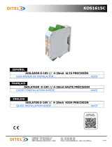
KOS1750B
20221007
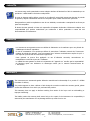
DISEÑOS Y TECNOLOGÍA, S.A.
Xarol, 6B P.I. Les Guixeres
08915 Badalona (Barcelona) - Spain
Tel. +34 933 394 758
Fax +34 934 903 145
Email: comercial@ditel.es ; web: www.ditel.es
ESPAÑOL
COMPARADOR MAYOR / MENOR PARA SEÑALES DE PROCESO
FRANÇAIS
PLUS GRANDE / PLUS PETITE POUR DES SIGNAUX DE PROCESS
ENGLISH
HIGHEST / LOWEST VALUE COMPARATOR FOR PROCESS SIGNALS
GUIA RÁPIDA DE INSTALACIÓN .............................................. 02/03
GUIDE D'INSTALLATION RAPIDE ............................................. 04/05
QUICK INSTALLATION GUIDE .................................................. 06/07
DOWNLOAD
USER MANUAL

2
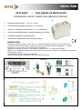
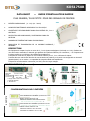
ENTRADA CONFIGURABLE ( 0 - 10V, 0/4 - 20mA)
ALIMENTACIÓN UNIVERSAL EXTENDIDA 20-250 VAC/DC
CONTROL Y DISPARO EN SISTEMAS CON 2, 3 ó 4 CAPTADORES
PROTECCIÓN DE SOBRECARGAS / SOBRETENSIONES EN MOTORES
ALARMAS DE TEMPERATURA EN PROCESOS
INDICACIÓN Y TRANSMISIÓN DE LA VARIABLE MÁXIMA
DESCRIPCIÓN
Este equipo compara la mayor o menor de 2, 3 o 4 señales analógicas 0/4-20mA ó 0-10V, dando como
resultado una única salida, máxima ó mínima que actúa en sistemas de alarma, controladores,… donde lo
importante es el valor mayor o menor de diversos transductores.
Simplifica los controles al colocar un solo módulo de alarma para 2, 3 ó 4 elementos a evaluar.
Admite en sus entradas tanto bucles de corriente activos como pasivos, y la salida es configurable en intensidad
(pasiva/activa) o tensión.
La capacidad de carga de salida está amplificada.
Dispone de alimentación universal (24-230V) con amplios márgenes.
DATA SHEET — GUIA RÁPIDA DE INSTALACIÓN
COMPARADOR MAYOR / MENOR PARA SEÑALES DE PROCESO
KOS1750B
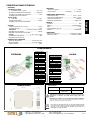
CONFIGURACIONES (frontal)
ACCESO A CONFIGURACIONES
INTERNAS SELECCIÓN DE SALIDA 0/4mA
SELECCIÓN DE ENTRADAS
SELECCIÓN
SALIDA
MAYOR
MENOR
AJUSTES DE ESCALA
INICIO = CERO
FINAL = SPAN
SELECCIÓN
SALIDA
0-10V
0/4-20mA
El ajuste de CERO y SPAN se realiza en 2 pasos:
1- AJUSTE GRUESO
2– AJUSTE FINO
Todos los Switch deben seleccionarse en V o en mA

3
20221007
DISEÑOS Y TECNOLOGÍA, S.A.
Xarol, 6B P.I. Les Guixeres
08915 Badalona (Barcelona) - Spain
Tel. +34 933 394 758
Fax +34 934 903 145
Email: comercial@ditel.es ; web: www.ditel.es
ESPECIFICACIONES TÉCNICAS
ENTRADAS
Intensidad 0/4-20mA
2 .. 4 Entradas (pasivo / activo)……….………….……….A, B, C, D
Alimentación aislada para bucles pasivos ..…………..15V/20mA
Impedancia de entrada (con protección)….……………..... 120Ω
Protegida contra sobrecorrientes
Tensión 0-10V
2 .. 4 Entradas …………………………………………………...0—10V
Impedancia de entrada .………………………………………….500kΩ
Protegido contra inversión de polaridad
SALIDAS
Tiempo de respuesta (10%...90%)…..………………………..50ms
Frecuencia de corte ..………………………….…………………… 11Hz
Intensidad.….……………………… (0-20mA / 4-20mA / 0-5mA)
Capacidad de carga máxima …………...………………………≤700Ω
Protegidas contra inversión de polaridad
Tensión ………...……………………………….(0-10V / ±10v / 0-5V)
Capacidad de carga máxima….………………………………... ≥ 1kΩ
Protegida contra cortocircuito
ALIMENTACIÓN UNIVERSAL
Tensión de alimentación………….……………...24 / 230 VAC / DC
Margen extendido…..………………………………..20 a 250 VAC/DC
Consumo máximo ….………………………………………………… 2.5W
PRECISIÓN
Máximo error global……………………………………………….. 0.05%
Deriva térmica …….…...……………I:0.05uA/ºC / V: 0.2mV/ºC
CONDICIONES AMBIENTALES
Temperatura trabajo …………………………………. -10ºC ÷ +60ºC
Temperatura almacenamiento ……………………. -40ºC ÷ +80ºC
Tiempo de calentamiento ...……………………………….. 5 minutos
Coeficiente de temperatura ……………………………... 50ppm / ºC
FORMATO
Protección ………………………………………………………………….. IP20
Material…………………………….………………………...Poliamida PA6.6
Peso ..…..……………………………………….……………………………100g
Combustibilidad según UL ……………………………………………...V0
Montaje …………………………………………………………. rail EN50022
CONEXIONES
Bornes por tornillo M3………………………….. par de apriete 0.5Nm
Cable de conexión…………………………………….≤2.5mm² (12AWG)
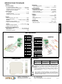
DIMENSIONES
CONEXIONADO
Directivas EMC 2014/30/EU LVD 2014/35/EU
Normas EN 61000-6-2
EN 61000-6-3 EN 61010-1
Conformidad CE .
ATENCIÓN: Si este instrumento no se instala y utiliza de acuerdo con estas
instrucciones, la protección que brinda contra riesgos puede verse
afectada
Para cumplir con los requisitos de la norma EN 61010-1, donde la unidad está
permanentemente conectada a la fuente de alimentación principal, es obligatorio
instalar un dispositivo de corte de circuito fácilmente accesible para el operador y
claramente marcado como dispositivo de desconexión.
SALIDA 4-20mA PASIVA
PIN 7 +EXC (Externa 24V)
PIN 8 + I OUT
PIN 9 LIBRE
De acuerdo con la Directiva 2012/19 / UE, no puede desecharlo al final
de su vida útil como basura municipal sin clasificar. Puede devolverlo,
sin ningún costo, al lugar donde fue adquirido para proceder a su
tratamiento y reciclaje controlados.
SALIDA 0/4-20mA
ACTIVA
PIN 7 LIBRE
PIN 8 +I
PIN 9 - I
SALIDA 0-10V / ±10V
PIN 7 LIBRE
PIN 8 +V
PIN 9 - V
ALIMENTACIÓN
PIN 10 VAC (L) / VDC (+)
PIN 11 LIBRE
PIN 12 VAC (N) / VDC (-)
ENTRADA 4-20mA
PASIVA
PIN 1 - I (A)
PIN 2 - I (B)
PIN 3 - I (C)
PIN 4 + EXC (interna)
PIN 5 - I (D)
PIN 6 LIBRE
ENTRADAS SALIDA
ENTRADA 4-20mA
ACTIVA
PIN 1 +I (A)
PIN 2 +I (B)
PIN 3 +I (C)
PIN 4 LIBRE
PIN 5 LIBRE
PIN 6 - I (A,B,C)
ENTRADA 0 -10V
PIN 1 +V (A)
PIN 2 +V (B)
PIN 3 +V (C)
PIN 4 LIBRE
PIN 5 LIBRE
PIN 6 -V (0V) A,B,C
ESPAÑOL

4
ENTRÉE CONFIGURABLE ( 0 - 10V, 0/4 - 20mA)
ALIMENTATION ÉTENDUE UNIVERSELLE 20-250 VAC/DC
CONTRÔLE ET DÉCLENCHEMENT DANS LES SYSTÈMES À 2, 3 ou 4
CAPTEURS
PROTECTION DES SURCHARGES / SURTENSIONS DANS LES
MOTEURS
ALARMES DE TEMPÉRATURE DANS LES PROCESSUS
INDICATION ET TRANSMISSION DE LA VARIABLE MAXIMALE /
MINIMALE
DESCRIPTION
Cet équipement compare le plus ou moins de 2, 3 ou 4 signaux analogiques 0/4-20mA ou 0-10V, résultant en
une seule sortie maximale ou minimale qui agit dans les systèmes d'alarme, les contrôleurs,... où l'important est
le valeur supérieure ou inférieure des différents transducteurs.
Il simplifie les contrôles en plaçant un seul module d'alarme pour 2, 3 ou 4 éléments à évaluer.
Il admet dans ses entrées des boucles de courant actives et passives, et la sortie est configurable en intensité
(passive/active) ou en tension. La capacidad de carga de salida está amplificada.
Il dispose d'une alimentation universelle (24-230V) avec de larges marges.
DATA SHEET — GUIDE D'INSTALLATION RAPIDE
PLUS GRANDE / PLUS PETITE POUR DES SIGNAUX DE PROCESS
KOS1750B
CONFIGURATIONS (face avant)
ACCÈS AUX RÉGLAGES SÉLECTION DE SORTIE 0/4mA
SÉLECTION D’ENTRÉES
SÉLECTION
SORTIE
PLUS GRANDE
PLUS PETITE
RÉGLAGES D'ÉCHELLE
DÉBOUT = ZERO
FIN = SPAN
SELECTION
SORTIE
0-10V
0/4-20mA
Le réglage ZERO et SPAN se fait en 2 étapes :
1- REGLAGE GROSSIER
2– RÉGLAGE FIN
Tous les commutateurs doivent être sélectionnés en V ou mA
CONFIGURATION POUR 2 ENTRÉES
PLUS GRANDE DE 2 ENTRÉES 0/4-20mA ou 0-10V
PLUS PETITE DE 2 ENTRÉES 0/4-20mA ou 0-10V
Utiliser comme entrées A et B
Laissez les entrées C et D non connectées
Utiliser comme entrées A et B
Laissez les entrées C et D en mode
Connecter les entrées C et D à +Exc
exemple

5
20221007
DISEÑOS Y TECNOLOGÍA, S.A.
Xarol, 6B P.I. Les Guixeres
08915 Badalona (Barcelona) - Spain
Tel. +34 933 394 758
Fax +34 934 903 145
Email: comercial@ditel.es ; web: www.ditel.es
SPÉCIFICATIONS TECHNIQUES
ENTRÉES
Courant 0/4-20mA
2 .. 4 Entrées (passive / active) …….………….……….A, B, C, D
Alimentation isolée pour boucles passives ………..15V/20mA
Impédance d'entrée (avec protection) .….……………..... 120Ω
Protégé contre les surintensités
Tension 0-10V
2 .. 4 Entrées …………………………………………………...0—10V
Impèdance d’entrée .………………………………………….500kΩ
Protégé contre l'inversion de polarité
SORTIES
Temps de réponse (10%...90%) .…..………………………..50ms
Fréquence de coupure ……………………….…………………… 11Hz
Courant ….….……………………… (0-20mA / 4-20mA / 0-5mA)
Capacité de charge maximale ………...………………………≤700Ω
Protégé contre l'inversion de polarité
Tension ………...……………………………….(0-10V / ±10v / 0-5V)
Capacité de charge maximale .………………………………... ≥ 1kΩ
Protégé contre les courts-circuits
ALIMENTATION UNIVERSELLE
Tension d’alimentation .………….……………...24 / 230 VAC / DC
Marge étendue …..………………………………..20 a 250 VAC/DC
Consommation maximale …………………………………… 2.5W
PRÉCISION
Erreur maximale globale ……………………………………….. 0.05%
Dérive thermique .…...……………I:0.05uA/ºC / V: 0.2mV/ºC
ENVIRONNEMENT
Température fonctionnement ………………………. -10ºC à+60ºC
Température de stockage …….……………………. -40ºC à +80ºC
Temps de chauffage ……......……………………………….. 5 minutes
Coéfficent de température ...……………………………... 50ppm / ºC
FORMAT
Protection ………………………………………………………………….. IP20
Materiel ………………………….………………………...Polyamide PA6.6
Poids .…..……………………………………….……………………………100g
Combustibilité selon UL ..……………………………………………...V0
Montage …………………………………………………………. rail EN50022
CONNEXIONS
Bornes à vis M3 ……….…………………………………… Torque 0.5Nm
Câble de connexion . ……………………………...≤2.5mm² (12AWG)
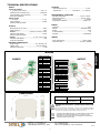
DIMENSIONS
RACCORDEMENT
SORTIE 4-20mA
PASSIVE
PIN 7 +EXC (Externe 24V)
PIN 8 + I OUT
PIN 9 LIBRE
SORTIE 0/4-20mA
ACTIVE
PIN 7 LIBRE
PIN 8 +I
PIN 9 - I
SORTIE 0-10V / ±10V
PIN 7 LIBRE
PIN 8 +V
PIN 9 - V
ALIMENTATION
PIN 10 VAC (L) / VDC (+)
PIN 11 LIBRE
PIN 12 VAC (N) / VDC (-)
ENTRÉE 4-20mA
PASSIVE
PIN 1 - I (A)
PIN 2 - I (B)
PIN 3 - I (C)
PIN 4 + EXC (interne)
PIN 5 - I (D)
PIN 6 LIBRE
ENTRÉES SORTIES
ENTRÉE 4-20mA
ACTIVE
PIN 1 +I (A)
PIN 2 +I (B)
PIN 3 +I (C)
PIN 4 LIBRE
PIN 5 LIBRE
PIN 6 - I (A,B,C)
ENTRÉE 0 -10V
PIN 1 +V (A)
PIN 2 +V (B)
PIN 3 +V (C)
PIN 4 LIBRE
PIN 5 LIBRE
PIN 6 -V (0V) A,B,C
ATTENTION : Si cet instrument n'est pas installé et utilisé conformément à
ces instructions, la protection qu'il offre contre les dangers peut être
altérée.
Pour répondre aux exigences de la norme EN 61010-1, où l'unité est connectée en
permanence à l'alimentation principale, il est obligatoire d'installer un dispositif de
coupure facilement accessible à l'opérateur et clairement identifié comme un
dispositif de déconnexion.
Selon la Directive 2012/19/UE, l’utilisateur ne pout se défaire de cet
appareil comme d’un residu urbain courant. Vous pouvez le restituer,
sans aucun coût, au lieu où il a eté acquis afin qu’il soit procédé à son
traitement et recyclage contrôlés.
Directives EMC 2014/30/EU LVD 2014/35/EU
Normes EN 61000-6-2
EN 61000-6-3 EN 61010-1
Conformité CE .
FRANÇAIS

6
CONFIGURABLE INPUT ( 0 - 10V, 0/4 - 20mA)
UNIVERSAL EXTENDED POWER SUPPLY 20-250 VAC/DC
CONTROL AND TRIGGER IN SYSTEMS WITH 2, 3 or 4 SENSORS
PROTECTION OF OVERLOADS / OVERVOLTAGES IN MOTORS
TEMPERATURE ALARMS IN PROCESSES
INDICATION AND TRANSMISSION OF THE HIGHEST
OR LOWEST INPUT VALUE
DESCRIPTION
This equipment compares the highest or lowest value of 2, 3 or 4 0/4-20mA or 0-10V analog signals, resulting in
a single maximum or minimum output that acts in alarm systems, controllers,... where the important thing is the
higher or lower value of various transducers.
It simplifies the controls by placing a single alarm module for 2, 3 or 4 elements to be evaluated.
It admits in its inputs both active and passive current loops, and the output is configurable in current (passive/
active) or voltage.
The output load capacity is amplified.
It has a universal power supply (24-230V) with wide margins.
DATA SHEET — QUICK INSTALLATION GUIDE
HIGHEST / LOWEST VALUE COMPARATOR FOR PROCESS SIGNALS
KOS1750B
CONFIGURATIONS (frontal)
ACCESS TO INTERNAL
SETTINGS 0/4mA OUTPUT SELECTION
INPUT SELECTION
OUTPUT
SELECTION
MAJOR
MINOR
SCALE ADJUSTMENTS
START = ZERO
END = SPAN
OUTPUT
SELEC-
TION
0-10V
ZERO and SPAN adjustment is done in 2 steps:
1- COARSE ADJUSTMENT
2– FINE ADJUSTMENT
All Switches must be selected in V or mA
example
CONFIGURATION for 2 INPUTS
MAJOR
MINOR
HIGHEST VALUE OF 2 INPUTS. 0/4-20mA or 0-10V
LOWEST VALUE OF 2 INPUTS. 0/4-20mA or 0-10V
Use as inputs &
&
&
in mode
Inputs configuration
Connect the inputs to +Exc
Leave inputs unconnected
&
&
Use inputs

7
20221007
DISEÑOS Y TECNOLOGÍA, S.A.
Xarol, 6B P.I. Les Guixeres
08915 Badalona (Barcelona) - Spain
Tel. +34 933 394 758
Fax +34 934 903 145
Email: comercial@ditel.es ; web: www.ditel.es
TECHNICAL SPECIFICATIONS
INPUTS
Current 0/4-20mA
2 .. 4 Inputs (sink / source) ….……….………….……….A, B, C, D
Isolated power for passive loops ……….....…………..15V/20mA
Input impedance (with protection) ……..….……………..... 120Ω
Overcurrent protection
Voltage 0-10V
2 .. 4 Inputs ... …………………………………………………...0—10V
Input impedance ……....………………………………………….500kΩ
Reverse polarity protection
OUTPUTS
Response time (10%...90%) ……...…..………………………..50ms
Cutoff frequency …....………………………….…………………… 11Hz
Current …...….……………………… (0-20mA / 4-20mA / 0-5mA)
Maximum load capacity …..…………...………………………≤700Ω
Reverse polarity protection
Voltage ……...……………………………….(0-10V / ±10v / 0-5V)
Maximum load capacity ….….………………………………... ≥ 1kΩ
Overcurrent protection
UNIVERSAL POWER SUPPLY
Supply voltaje…………...………….……………...24 / 230 VAC / DC
Voltage range ..…..………………………………..20 a 250 VAC/DC
Maximum consumption ………………………………………… 2.5W
ACCURACY
Overall maximum error ……………………………………….. 0.05%
Thermal drift ..…….…...……………I:0.05uA/ºC / V: 0.2mV/ºC
ENVIRONMENTAL CONDITIONS
Operating temperature ……………………………. –10ºC to +600ºC
Storage temperature .….……………………………….-40ºC to +80ºC
Warm-up time ………...…...………………………………….. 5 minutes
Temperature coefficient .…………………………………... 50ppm / ºC
FORMAT
Protection …………………………………………………………………... IP20
Material …………………………………………………...Polyamide PA6.6
Weight ………………………...………………………………………….140g
UL Combustibility ……………………………………………………………..V0
Mounting …………………………………………………………..rail EN50022
WIRING
Screw terminals M3 ………...……………………………... torque 0.5Nm
Connection cable .……………………………………..≤2.5mm² (12AWG)
DIMENSIONS
WIRING
OUTPUT 4-20mA SINK
PIN 7 +EXC (external 24V)
PIN 8 + I OUT
PIN 9 N.C.
OUTPUT 0/4-20mA
SOURCE
PIN 7 N.C.
PIN 8 +I
PIN 9 - I
OUTPUT 0-10V / ±10V
PIN 7 N.C.
PIN 8 +V
PIN 9 - V
POWER SUPPLY
PIN 10 VAC (L) / VDC (+)
PIN 11 N.C.
PIN 12 VAC (N) / VDC (-)
INPUT 4-20mA SINK
PIN 1 - I (A)
PIN 2 - I (B)
PIN 3 - I (C)
PIN 4 + EXC (internal)
PIN 5 - I (D)
PIN 6 N.C.
INPUTS OUTPUT
INPUT 4-20mA
SOURCE
PIN 1 +I (A)
PIN 2 +I (B)
PIN 3 +I (C)
PIN 4 N.C.
PIN 5 N.C.
PIN 6 - I (A,B,C)
INPUT 0 -10V
PIN 1 +V (A)
PIN 2 +V (B)
PIN 3 +V (C)
PIN 4 N.C.
PIN 5 N.C.
PIN 6 -V (0V) A,B,C
Directives EMC 2014/30/EU LVD 2014/35/EU
Standarts EN 61000-6-2
EN 61000-6-3 EN 61010-1
CE Conformity.
ATTENTION: If this instrument is not installed and used in accordance with
these instructions, the protection it provides against hazards may be
impaired.
To meet the requirements of EN 61010-1, where the unit is permanently connected
to the main power supply, it is mandatory to install a circuit-breaking device easily
accessible to the operator and clearly marked as a disconnect device.
According to 2012/19/EU Directive, You cannot dispose of it at the end
of its lifetime as unsorted municipal waste. You can give it back,
without any cost, to the place where it was adquired to proceed to its
controlled treatment and recycling.
ENGLISH

8
20221007
DISEÑOS Y TECNOLOGÍA, S.A.
Xarol, 6B P.I. Les Guixeres
08915 Badalona (Barcelona) - Spain
Tel. +34 933 394 758
Fax +34 934 903 145
Email: comercial@ditel.es ; web: www.ditel.es
Los instrumentos están garantizados contra cualquier defecto de fabricación o fallo de materiales por un
periodo de 3 AÑOS desde la fecha de su adquisición.
En caso de observar algún defecto o avería en la utilización normal del instrumento durante el periodo
de garantía, diríjase al distribuidor donde fue comprado quien le dará instrucciones oportunas.
Esta garantía no podrá ser aplicada en caso de uso indebido, conexionado o manipulación erróneos por
parte del comprador.
El alcance de esta garantía se limita a la reparación del aparato declinando el fabricante cualquier otra
responsabilidad que pudiera reclamársele por incidencias o daños producidos a causa del mal
funcionamiento del instrumento.
GARANTÍA
Les instruments sont garantis contre tout défaut de fabrication ou de matériaux pour une période de
3 ANS depuis la date d´acquisition.
En cas de constatation d´un quelconque défaut où avarie dans l´utilisation normale de l´instrument
pendant la période de garantie, il est recommandé de s´adresser au distributeur auprès de qui il a
été acquis et qui donneras les instructions opportunes.
Cette garantie ne pourra être appliquée en cas d´utilisation anormale, raccordement ou
manipulations erronés de la part de l´utilisateur.
La validité de cette garantie se limite a la réparation de l´appareil et n´entraîne pas la responsabilité
du fabricant quant aux incidentes ou dommages causés par le mauvais fonctionnement de
l´instrument.
GARANTIE
The instruments are warranted against defective materials and workmanship for a period of 3 YEARS
from date of delivery.
If a product appears to have a defect or fails during the normal use within the warranty period, please
contact the distributor from which you purchased the product.
This warranty does not apply to defects resulting from action of the buyer such as mishandling or
improper interfacing.
The liability under this warranty shall extend only to the repair of the instrument. No responsibility is
assumed by the manufacturer for any damage which may result from its use.
WARRANTY
-
 1
1
-
 2
2
-
 3
3
-
 4
4
-
 5
5
-
 6
6
-
 7
7
-
 8
8