PeakTech P3710 Le manuel du propriétaire
- Catégorie
- Mesure, test
- Taper
- Le manuel du propriétaire

3
4 5 6
2
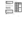
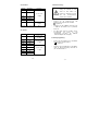
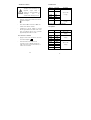
2.5 Diode Test
Range description Test
Condition
2V
Display read
approx.
forward
voltage of
diode
Forward DC
Current:
approx.
1mA
Reversed
DC Voltage:
approx.
2.8V
2.6 Continuity check
The buzzer generates 2kHZ beep whenever the
reading is less than 30Ω.
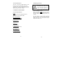
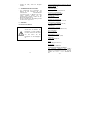
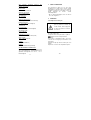
3. DESCRIPTION
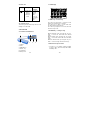
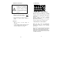
3.1 Instrument Familiarization
1. cathode
2. anode
3. ”RANGE” key
4. ”FUNC.” key
5. LCD display
6. Battery cover
-25-
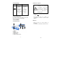
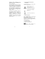
3.2 LCD Display
3.3 FUNC. key----Function key
Press this key longer than 1 second, the meter
will turn on and enter auto scan mode.
Press this key less than 1 second could select
the target measurement function.
Press this key longer than 2 seconds, the meter
will enter sleep mode.
3.4 RANGE key ----Changes range
When automatic mode pressing this key less
than 1 second, the meter will enter manual
mode.
When manual mode pressing this key longer
than 1 second, the meter will enter automatic
mode.
While in manual mode, pressing this key less
than 1 second to change the full-scale range.
3.5 Measurement specifications
* Accuracy: ± (% of reading + number of digits)
at 18OC to 28OC (64OF to 82OF) with relative
humidity to 80%.
-26-
1

Caution when working with
voltages above 50V DC or
36V AC rms.
4. OPERATING INSTRUCTION
4.1 Auto scan measurement mode
Pressing this key longer than 1 second, the
meter will turn on and enter auto scan
mode.now,you can measurement: ohm, diode,
capatitance and continuity check.
NOTE:
The range when auto scan mod:
Ohm: 600.0Ω~6.000MΩ;
Cap: 6nF~600µF.
4.2 Resistance measurement
To avoid electrical shock or
damages to the meter under
test, disconnect circuit power
and discharge all high-voltage
capacitors before measuring
resistance.
Press FUNC. Key and select the function at
- mode.Connect the test clip to the object
being measured and the measured value will
show on the display.
-27-
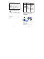
2.4 Capacitance
Range Resolution Accuracy
6nF 1pF ±(5.0% of rdg
+5 digits)
60nF 10pF
±(3.0% of rdg
+3 digits)
600nF 100pF
6µF 1nF
60µF 10nF
±(5.0% of rdg
+3 digits)
600µF 100nF
6mF 1uF
60mF 10uF
Keep two pins of the capacitance in short before
measuring
-24-

2.3 Resistance
Range Resolution
Accuracy
600 Ω 0.1 Ω
±(1.2% of rdg
+2digits)
6 kΩ 1 Ω
60 kΩ 10 Ω
600 kΩ 100 Ω
6 MΩ 1 kΩ
60 MΩ 10 kΩ ±(2% of rdg
+5digits)
-23-
NOTE:
When this mode the RANGE key is available,
when the input is not connected, i.e. at open
circuit, the figure "OL" will be displayed for the
overrange condition.
4.3 Capacitance measurement
To avoid electrical shock or
damages to the meter under
test, disconnect circuit power
and discharge all high-voltage
capacitors before measuring
capacitance. Keep two pins of
the capacitance in short before
measuring.
Press FUNC. Key and select the function at
mode.
Connect the test clip to the capacitor being
measured and read the displayed value.
NOTE:
When this mode the RANGE key is available.
discharge the capacitor before measuring.
4.4 Diode measurement
To avoid electrical shock or
damages to the meter under
test, disconnect circuit power
and discharge all high-voltage
capacitors before testing
diodes.
-28-

Press FUNC. Key and select the function at
mode.
Connect the + pin to the anode, the - pin to the
cathode of the diode under testing.
The meter will show the approx. forward voltage
of the diode. If the lead connection is reversed,
only figure "OL" displayed.
4.5 Continuity check
Press FUNC. Key and select the function at
mode connect the test clip to the
resistance. If continuity exists (i.e., resistance
less than 30Ω) built – in buzzer will sound.
5. AUTO POWER OFF(APO)
To extend the battery life, Auto Power Off
function is provided. If no key operations of
range changing happen about 10 minutes, the
meter will be turned off automatically.
When APO happens, the state of the meter is
saved.
6. MAINTENANCE
6.1 General Maintenance
Periodically wipe the case with a damp cloth and
mild detergent. Do not use abrasives or solvents.
-29-
Auto Power Off
after 10 minutes
Power supply
2x 1,5V buttom cells (AG-13)
Operating temperature:
0~40 OC, (<80% RH);
< 2000 m
Storage temperature:
-10~60 OC, (<70% RH, battery
removed)
Dimensions:
183(L) x 35(W) x 20(H) mm
Weight:
65g. . Approx. (battery included)
2.2 Measurement specifications
∗ Accuracy: ±(% of reading + number of
digits) at 18OC to 28OC (64OF to 82OF) with
relative humidity to 80%.
Caution when working with
voltages above 50V DC or
36V AC rms.
-22-

1.2 General Instructions
This auto scan pen-type SMD-multimeter could
fast precise measure small chip components.
To get the best service from this meter, please
read this user's manual carefully and observe the
detailed safety precautions strictly.
2. TECHNICAL SPECIFICATIONS
2.1 General specifications
Display
3 5/6 digit, 12 mm LCD display with function
annunciators, max. indication 5999
Max. Voltage between
terminals and earth ground
50V DC / 36V Acrms
Ranging method
Auto or manual
Sampling rate
3 times / second
Polarity indication
“-“ displayed automatically
Overload indication
“OL” displayed
Low battery indication
“BAT-Symbol” displayed
-21-
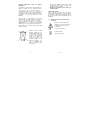
6.2 Battery replacement
Before replacing the battery,
disconnect test probes from
any circuit under test, turn the
meter off and remove test
probes from the input terminals.
Use the following procedure:
When the battery voltage drop below proper
operation range the symbol will appear on
the LCD display and the battery need to be
replaced.
Press the battery cover and towards arrowhead
direction to open the battery cover. Replace the
battery with two new 1.5V batteries (AG13).
Replace the battery cover.
-30-

Statutory Notification about the Battery
Regulations
The delivery of many devices includes batteries,
which for example serve to operate the remote
control. There also could be batteries or
accumulators built into the device itself. In
connection with the sale of these batteries or
accumulators, we are obliged under the Battery
Regulations to notify our customers of the
following:
Please dispose of old batteries at a council
collection point or return them to a local shop at
no cost. The disposal in domestic refuse is
strictly forbidden according to the Battery
Regulations. You can return used batteries
obtained from us at no charge at the address on
the last side in this manual or by posting with
sufficient stamps.
-31-
* Opening the equipment and service – and
repair work must only be performed by
qualified service personnel
* Measuring instruments don’t belong to
children hands.
Cleaning the cabinet
Clean only with a damp, soft cloth and a
commercially available mild household cleanser.
Ensure that no water gets inside the equipment
to prevent possible shorts and damage to the
equipment.
1.1. Symbols used in this manual and on
the meter:
Caution: refer to the instruction
manual. Incorrect use may result
in damage to the device or its
components.
conforms to IEC1010
Double insulation
(Protection class II)
-20-
Batteries, which contain
harmful substances, are
marked with the symbol of
a crossed-out waste bin,
similar to the illustration
shown left. Under the
waste bin symbol is the
chemical symbol for the
harmful substance, e.g.
„Cd“ for cadmium, „Pb“
stands for lead and „Hg“
for mercury.

* Never touch the tips of the test leads or
probe.
* Comply with the warning labels and other
info on the equipment.
* The measurement instrument is not to be to
operated unattended.
* Always start with the highest measuring
range when measuring unknown values.
* Do not subject the equipment to direct
sunlight or extreme temperatures, humidity
or dampness.
* Do not subject the equipment to shocks or
strong vibrations.
* Do not operate the equipment near strong
magnetic fields (motors, transformers etc.).
* Keep hot soldering irons or guns away from
the equipment.
* Allow the equipment to stabilize at room
temperature before taking up measurement
(important for exact measurements).
* Use caution when working with voltages
above 35V DC or 25V AC. These Voltages
pose shock hazard.
* Replace the battery as soon as the battery
indicator “BAT” appears. With a low battery,
the meter might produce false reading that
can lead to electric shock and personal
injury.
* Fetch out the battery when the meter will not
be used for long period.
* The meter is suitable for indoor use only
* Do not operate the meter before the cabinet
has been closed and screwed safely as
terminal can carry voltage.
* Do not store the meter in a place of
explosive, inflammable substances.
* Do not modify the equipment in any way
* Do not place the equipment face-down on
any table or work bench to prevent
damaging the controls at the front.
-19-
You can also find this notification in the
paperwork accompanying the goods delivery or
in the manufacturer’s operating instructions.
You can obtain further information about the
Battery Regulations from the Bundesministerium
für Umwelt, Naturschutz und Reaktorsicherheit
(Federal Ministry of Environment, Nature
Conservation and Reactor Safety).
All rights, also for translation, reprinting and copy
of this manual or parts are reserved.
Reproduction of all kinds (photocopy, microfilm
or other) only by written permission of the
publisher.
This manual considers the latest technical
knowing. Technical changings which are in the
interest of progress reserved.
e herewith confirm, that the units are calibrated
by the factory according to the specifications as
per the technical specifications. We recommend
to calibrate the unit again, after 1 year.
PeakTech
®
01/2010/th
-32-

1. SAFETY PRECAUTIONS
This product complies with the requirements of
the following European Community Directives:
2004/108/EC (Electromagnetic Compatibility)
and 2006/95/EC (Low Voltage) as amended by
2004/22/EC (CE-Marking).
Pollution degree 2.
To ensure safe operation of the equipment and
eliminate the danger of serious injury due to
short-circuits (arcing), the following safety
precautions must be observed.
Damages resulting from failure to observe these
safety precautions are exempt from any legal
claims whatever.
* Caution : Avoid working with voltages
above 50VDC or 36VAC rms. Such
voltages pose a shock hazard and
damage the meter
* Do not use this instrument for high-energy
industrial installation measurement.
* Do not place the equipment on damp or wet
surfaces.
* Disconnect test leads or probe from the
measuring circuit before switching modes or
functions.
* To avoid electric shock, disconnect power to
the unit under test and discharge all
capacitors before taking any resistance
measurements.
* Check test leads and probes for faulty
insulation or bare wires before connection to
the equipment.
* To avoid electric shock, do not operate this
product in wet or damp conditions. Conduct
measuring works only in dry clothing and
rubber shoes, i. e. on isolating mats.
-18-
PeakTech
®
3710
Mode d’emploi
Appareil de mesure crayon
pour SMD

1. INDICATIONS DE SECURITE
Cet appareil répond aux directives EU
2004/108/CE (compatibilité électromagétique) et
2006/95/CE (basse tension) conformément à la
modification 2004/22/CE (sigle CE).
Degré de pollution 2.
Pour un fonctionnement en toute sécurité de
l’appareil et pour éviter de graves blessures liées
aux claquages de courant ou de tension ou des
courts-circuits, les indications de sécurité citées
ci-dessous doivent absolument être respectées
lors du fonctionnement de l’appareil .
Les dommages causés par le non-respect de
ces indications sont exclus de la garantie.
* Attention: Ne pas utliser à des tensions
supérieures à 50VDC ou 36VAC
(effectives). Ces tensions présentent un
risque de décharge électrique et peuvent
endommager l’appareil de mesure.
* Cet appareil ne doit pas être utilisé dans des
montages hautement énergétiques.
* Ne pas placer l’appareil sur un support
humide ou mouillé.
* Ne pas utiliser l’appareil à proximité de
champs magnétiques forts (moteurs,
transformateurs etc.).
* Ne dépasser en aucune circonstance les
valeurs d’entrée maximales autorisées
(risque de blessure grave et/ou destruction
de l’appareil)
* N’utilisez jamais l’appareil s’il n’est pas
totalement fermé.
-34-
PeakTech
®
3710
Operation manual
Pen Meter for SMD

* Avant de passer à une autre fonction de
mesure, débracher les conducteurs de
contrôle ou le palpeur du circuit de mesure.
* Ne pas laisser l’appareil sans surveillance.
* N’appliquer aucune tension lors des
mesures de résistances!
* Vérifier les dommages éventuels de
l’appareil, des conducteurs de contrôle et
autres accessoires avant la mise en marche
et les câbles ou fils dénudés ou coudés. En
cas de doute, n’entreprendre aucune
mesure.
* Effectuer les travaux de mesure uniquement
avec des vêtements secs et de préférence
avec des gants en caoutchouc ou sur une
natte en caoutchouc .
* Ne pas toucher les pointes de mesure des
conducteurs de contrôle.
* Respecter impérativement les
avertissements sur l’appareil.
* L’appareil ne doit pas fonctionner sans
surveillance.
* Ne pas exposer l’appareil aux températures
extrêmes, au rayonnement direct du soleil, à
une humidité d’air extrême ou à l’humidité.
* Eviter les fortes secousses.
* Tenir éloigner les pistolets à souder chauds
de l’appareil.
* L’appareil doit être stabilisé à la température
ambiante (important en cas de transport
d'une pièce froide à une pièce chaude et
inversement)
* Entreprendre les mesures de tensions
supérieures à 35V DC ou 25V AC
uniquement en respectant les consignes de
sécurité. En cas de tensions plus élevées,
des décharges électriques particulièrement
dangereuses peuvent survenir.
-35-
Sie finden diese Hinweise auch noch einmal in
den Begleitpapieren der Warensendung oder in
der Bedienungsanleitung des Herstellers.
Weitere Hinweise zur Batterieverordnung finden
Sie beim Bundesministerium für Umwelt,
Naturschutz und Reaktorsicherheit.
Alle Rechte, auch die der Übersetzung, des
Nachdruckes und der Vervielfältigung dieser
Anleitung oder Teilen daraus, vorbehalten.
Reproduktionen jeder Art (Fotokopie, Mikrofilm
oder ein anderes Verfahren) nur mit schriftlicher
Genehmigung des Herausgebers gestattet.
Letzter Stand bei Drucklegung. Technische
Änderungen des Gerätes, welche dem
Fortschritt dienen, vorbehalten.
Hiermit bestätigen wir, dass alle Geräte, die in
unseren Unterlagen genannten Spezifikationen
erfüllen und werkseitig kalibriert geliefert werden.
Eine Wiederholung der Kalibrierung nach Ablauf
von 1 Jahr wird empfohlen
PeakTech
®
01/2010/th
-16-

Gesetzlich vorgeschriebene Hinweise zur
Batterieverordnung
Im Lieferumfang vieler Geräte befinden sich
Batterien, die z. B. zum Betrieb von
Fernbedienungen dienen. Auch in den Geräten
selbst können Batterien oder Akkus fest
eingebaut sein. Im Zusammenhang mit dem
Vertrieb dieser Batterien oder Akkus sind wir als
Importeur gemäß Batterieverordnung
verpflichtet, unsere Kunden auf folgendes
hinzuweisen:
Bitte entsorgen Sie Altbatterien, wie vom
Gesetzgeber vorgeschrieben- die Entsorgung im
Hausmüll ist laut Batterieverordnung
ausdrücklich verboten-, an einer kommunalen
Sammelstelle oder geben Sie sie im Handel vor
Ort kostenlos ab. Von uns erhaltene Batterien
können Sie nach Gebrauch bei uns unter der auf
der letzten Seite angegeben Adresse
unentgeltlich zurückgeben oder ausreichend
frankiert per Post an uns zurücksenden.
-15-
* Remplacez la pile dès que le symbole de la
pile “BAT“ s’allume. Une puissance moins
élevée de la pile peut entraîner des résultats
de mesure imprécis ainsi que des
décharges électriques et des dommages
corporels.
* Si vous n’utilisez pas l’appareil pendant une
période prolongée, retirez les piles du
compartiment à piles.
* Cet appareil est exclusivement destiné à
l’utilisation interne.
* Evitez toute proximité avec des matières
explosives et inflammables.
* L’ouverture de l’appareil et les travaux
d’entretien et de réparation doivent être
effectués uniquement par des techniciens
SAV qualifiés.
* Ne pas poser l’appareil face avant sur
l’établi ou la surface de travail pour éviter
d’endommager les éléments de commande.
* N’entreprendre aucune modification
technique sur l’appareil.
* - Ne pas laisser d’appareils de mesure à
portée de main des enfants -
Nettoyage de l’appareil:
Nettoyer l’appareil uniquement avec un chiffon
humide et non effiloché. Utiliser uniquement des
produits vendus dans le commerce. Lors du
nettoyage, veiller absolument à ce qu’aucun
liquide ne pénètre à l’intérieur de l’appareil. Cela
pourrait causer un court-circuit et la destruction
de l’appareil.
-36-
Batterien, die Schadstoffe
enthalten, sind mit dem
Symbol einer
durchgekreuzten Mülltonne
gekennzeichnet, ähnlich
dem Symbol in der
Abbildung links. Unter dem
Mülltonnensymbol befindet
sich die chemische
Bezeichnung des
Schadstoffes z. B. „CD“ für
Cadmium, „Pb“ steht für
Blei und „Hg“ für
Quecksilber.

1.1. Avertissement et symboles sur l’appareil
Les symboles utilisés dans ce manuel et sur
l’appareil de mesure sont:
Attention:
Consultez
le manuel
d’utilisation. L’utilisation non
conforme de l’instrument peut
endommager l’appareil ou ses
composants.
Répond aux normes IEC1010
Doublement isolé (classe de
protection II)
1.2. Indications générales
Ce multimètre crayon SMD pour SMD avec
fonction AutoScan mesure précisément et
rapidement les petits composants Chip .
Pour une utilisation optimale de cette appareil,
veuillez lire attentivement le présent manuel
d’utilisation et respectez les mesures de
sécurité.
2. DONNES TECHNIQUES
2.1. Spécifications générales
Affichage
Ecran LCD 12mm 5/6 lignes avec symboles des
fonctions, affichage max.: 5999
-37-
Gehen Sie wie folgt vor:
* Wenn die Batteriespannung unter den
ordnungsgemäßen Arbeitsbereich fällt,
erscheint das -Symbol im Display und
die Batterie muss ausgetauscht werden.
* Schieben Sie zum Öffnen des Batteriefachs
die Batteriefachabdeckung mit leichtem Druck
in Pfeilrichtung.
* Ersetzen Sie die Batterie durch zwei neue
1,5V-Batterien (AG13).
* Setzen Sie die Batterieabdeckung wieder auf.
-14-

* weniger als 30Ω), ertönt der integrierte
Summer.
5. AUTOMATISCHE ABSCHALTUNG
* Zur Verlängerung der Lebensdauer der
Batterie ist das Instrument mit einer
automatischen Abschaltefunktion
ausgerüstet. Wenn 10 Minuten lang keine
Tasten gedrückt werden, um den
Arbeitsbereich zu ändern, schaltet sich das
Messgerät automatisch ab.
* Bei der automatischen Abschaltung werden
die Ablesewerte gespeichert.
6. WARTUNG
6.1 Austausch der Batterie
Trennen Sie vor dem
Austauschen der Batterie die
Prüfspitzen von dem geprüften
Kreislauf, schalten Sie das Gerät
aus und ziehen Sie die
Prüfspitzen von den Eingängen
ab.
-13-
Tension maximale autorisée entre les entrées et
la mise à la terre
50V DC / 36V AC eff
Choix de la gamme
Automatiquement ou manuellement
Fréquence d’échantillonage:
3 S/s pour données numériques
Affichage de surcharge
“OL“ apparaît
Affichage de l’état de la pile
“Symbole batterie“ apparaît sur l’écran
Température d’exploitation
0 ... +40°C (<80% d’humidité de l’air)
< 2000m n.N.
Température de stockage
-10 ... + 60°C (<70% d’humidité de l’air)
Arrêt automatique
Après 10 minutes
Alimentation en courant
2 piles 1,5V/piles rondes (357A)
Dimensions
183(L)×35(l)×20(H) mm
Poids
environ 65g. (piles incluses)
Accessoires
Piles et manuel d’utilisation
2.2. Fonctions de mesure et gammes
Les précisions indiquées sont valables
uniquement pendant un an après le calibrage.
Gamme de températures pour une précision
garantie: 18° C...28° C, < 75 % d’humidité de
l’air -38-

2.3 Résistance
Gamme
Résolution
Précision:
600 Ω 0,1Ω
±(1,2% v.M.
+ 2 dgt.)
6kΩ 1Ω
60kΩ 10Ω
600kΩ 100Ω
6MΩ 1kΩ
60MΩ 10kΩ ±(2% v.M.
+ 5 dgt.)
Protection contre la surcharge: 250 V
DC/ACeff
2.4 Capacité
Gamme
Résolution
Précision
6nF 1pF ±(5,0% v.M.
+5 dgt.)
60nF 10pF ±(3,0% v.M.
+3 dgt.)
600nF 100pF
6µF 1nF
60µF 10nF
±(5,0% v.M.
+3 dgt.)
600µF 100nF
6mF 1uF
60mF 10uF
-39-
4.4 Diodenmessung
Zur Vermeidung von Strom-
schlag oder Schäden an dem
Gerät vor dem Prüfen von
Dioden den Stromkreis trennen
und alle Hochspannungs-
kondensatoren entladen.
* Drücken Sie die Funktions-Taste und
wählen Sie die entsprechende Funktion
- Symbol aus.
* Schließen Sie den +-Stift an die Anode, den
– -Stift an die Kathode der zu prüfenden
Diode an.
* Das Messgerät zeigt die ungefähre Durch-
lassspannung der Diode an. Bei
umgekehrtem Anschluss der Prüfleiter
erscheint lediglich "OL" im Display.
4.5 Durchgangsprüfung
* Drücken Sie die Funktions-Taste und wählen
Sie die entsprechende Funktion
- Symbol aus.
* Schließen Sie die Prüfklemme an den Wider-
stand an. Wenn Durchgang vorhanden ist
(d.h. der Widerstand ist
-12-

1 3
2 4 6
5
4.3 Kapazitätsmessung
Zur Vermeidung von
Stromschlag oder Schäden an
dem Gerät, vor dem Messen
der Kapazität, den Stromkreis
trennen und alle Hoch-
spannungskondensatoren
entladen.
* Drücken Sie die Funktions-Taste und
wählen Sie die entsprechende Funktion -
-Symbol aus.
* Schließen Sie die Prüfklemme an den zu
messenden Kondensator an und lesen den
Anzeigewert ab.
Hinweis:
* In diesem Modus ist die Bereichs-Taste
verfügbar.
* Entladen Sie den Kondensator vor der
Messung!
-11-
2.5 Contrôle des diodes
Gamme
Description
Condition de
contrôle
2V
Lecture écran
tension
directe
approximative
de la diode
Courant test
(DC) :
Environ 1mA
Tension
inverse (DC) :
Environ 2,8V
2.6 Contrôle de continuité
Le vibreur sonore produit un son de 2khz lorsque
la valeur lue s’élève à moins de 30Ω.
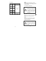
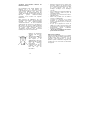
3. DESCRIPTION
3.1 Eléments de commande :
1. Cathode
2. Anode
3. Touche Range
4. Touche Fonction
5. Ecran LCD
6. Couvercle du compartiment à piles
-40-

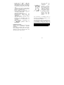
3.2 Affichage LCD
3.3 Touche de fonction – Choix de la fonction
Si vous appuyez plus d’1 seconde sur cette
touche, l’appareil de mesure se met en marche
et passe en mode de lecture automatique
(AutoScan).
Si vous appuyer moins d’1 seconde sur cette
touche, vous pouvez choisir la fonction de
mesure souhaitée.
Si vous appuyez plus de 2 secondes, l’appareil
s’arrête à nouveau.
3.4 Touche Range – Modifier gamme
Si en mode de mesure automatique vous
appuyez moins d’1 seconde sur cette touche,
l’instrument passe en mode de mesure manuel.
Si en mode de mesure automatique vous
appuyez plus d’1 seconde sur cette touche,
l’instrument passe en mode de mesure
automatique.
Si vous appuyez sur cette touche en mode de
mesure manuel moins d’1 seconde, vous pouvez
modifier l’ensemble de la gamme.
-41-
4.2 Widerstandsmessung
Zur Vermeidung von
Stromschlag oder Schäden an
dem Gerät vor dem Messen
des Widerstandes den
Stromkreis trennen und alle
Hochspannungskonden-
satoren entladen.
* Drücken Sie die Funktions-Taste und
wählen Sie die entsprechende Funktion
-Symbol aus.
* Schließen Sie die Prüfklemme an das zu
prüfende Objekt an. Der Messwert wird im
Display angezeigt.
Hinweis:
* In diesem Modus ist die Bereichs-Taste
verfügbar.
* Wenn der Eingang nicht angeschlossen ist,
d.h. bei offener Last, erscheint "OL" im
Display zur Angabe einer Überlastung.
-10-

3.5 Messspezifikationen
* Genauigkeit: ±(% Ablesewert + Anzahl an
Ziffern) bei 18°C bis 8°C (64°F bis 82°F) mit
relativer Feuchtigkeit von bis zu 80%.
Achtung beim Arbeiten mit
Spannungen von über 50VDC
oder 36VAC (effektiv)!
4. MESSBETRIEB
4.1 AutoScan-Messmodus
Wenn Sie diese Taste länger als 1 Sekunde
drücken, schaltet sich das Messgerät ein und
wechselt in den automatischen Ablesemodus
(AutoScan). Nun können Sie die folgenden
Messungen vornehmen:
Ohm, Diode, Kapazitanz, Durchgangsprüfung.
Hinweis:
Der Bereich im AutoScan-Modus beträgt:
Ohm: 600.0Ω~6.000MΩ;
Kap.: 6nF~600µF
-9-
3.5 Spécifications de mesure
* Précision: ±(% valeur lue + nombre de
chiffres) de 18°C à 8°C avec humidité relative
jusqu’à 80%.
Attention en cas de travaux
avec des tensions supérieures
à 50VDC ou 36VAC
(effectives)!
4. 4. MODE MESURE
4.2 Mode mesure AutoScan
Si vous appuyez plus d’1 seconde sur cette
touche, l’appareil de mesure se met en marche
et passe en mode de lecture automatique
(AutoScan). Vous pouvez entreprendre les
mesures suivantes:
Ohm, diode, capacitance, contrôle de continuité.
Indication :
La gamme en mode AutoScan s’élève à:
Ohm: 600.0Ω~6.000MΩ;
Cap : 6nF~600µF
-42-

4.2 Mesure de la résistance
Pour éviter une décharge
électrique ou des dommages
sur l’appareil, couper avant de
mesurer la capacité le circuit
électrique et décharger tous
les condensateurs à haute
pression.
* Appuyez sur la touche Fonction et choisissez
le symbole de la fonction adéquate
* Raccordez la borne de contrôle à l’objet à
contrôler. La valeur mesurée s’affiche à
l’écran.
Indication :
* Dans ce mode, la touche Range est
disponible.
* Lorsque l’entrée n’est pas raccordée, à savoir
en cas de charge ouverte, "OL" s’affiche à
l’écran pour indiquer une surcharge.
-43-
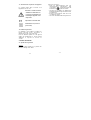
3.2 LCD-Anzeige
3.3 Funktionstaste ---- Funktionsauswahl
Wenn Sie diese Taste länger als 1 Sekunde
drücken, schaltet sich das Messgerät ein und
wechselt in den automatischen Ablesemodus
(AutoScan).
Wenn Sie diese Taste weniger als 1 Sekunde
drücken, können Sie die gewünschte
Messfunktion auswählen.
Wenn Sie diese Taste länger als 2 Sekunden
drücken, schaltet sich das Gerät wieder aus.
3.4 Bereichstaste ---- Bereich ändern
Wenn Sie diese Taste im automatischen
Messmodus weniger als 1 Sekunde drücken,
wechselt das Instrument in den manuellen
Messmodus.
Wenn Sie diese Taste im manuellen Messmodus
länger als 1 Sekunde drücken, wechselt das
Instrument in den automatischen Messmodus.
Wenn Sie diese Taste im manuellen Messmodus
weniger als 1 Sekunde drücken, können Sie den
Gesamtbereich ändern.
-8-

2.5 Diodenprüfung
Bereich Beschreibung Prüfbedingung
2V
Display-
ablesung
ungefähre
Durchlass-
spannung der
Diode
Teststrom
(DC):
ca. 1mA
Sperrspan-
nung (DC):
ca. 2,8V
2.6 Durchgangsprüfung
Der Summer erzeugt einen 2kHz-Ton, wenn der
Ablesewert weniger als 30Ω beträgt.
3. BESCHREIBUNG
3.1 Bedienelemente:
1. Kathode
2. Anode
3. Range-Taste
4. Funktions-Taste
5. LCD-Display
6. Batteriefachabdeckung
-7-
4.3 Mesure de capacité
Pour éviter une décharge
électrique ou des dommages
sur l’appareil, couper avant
de mesurer la capacité le
circuit électrique et décharger
tous les condensateurs à
haute pression.
* Appuyez sur la touche Fonction et choisissez
le symbole .
* Raccordez la borne de contrôle au
condensateur à mesurer et lisez la valeur
affichée.
Indication :
* Dans ce mode, la touche Range est
disponible.
* Déchargez le condensateur avant la mesure!
-44-
1 3
4 5 6
2

4.4 Mesure de diodes
Pour éviter une décharge
électrique ou des dommages sur
l’appareil, couper avant le
contrôle le circuit électrique et
décharger tous les
condensateurs à haute pression.
* Appuyez sur la touche Fonction et choisissez
la fonction adéquate
-.
* Raccordez le Stift + à l’anode, le Stift - à la
cathode de la diode à contrôler.
* L’appareil de mesure indique la tension
directe approximative de la diode. Dans le cas
d’un raccordement inversé des opérateurs
apparaît uniquement "OL" à l’écran.
4.5 Contrôle de continuité
* Appuyez sur la touche Fonction et choisissez
la fonction adéquate
* Raccordez la borne de contrôle à la
résistance. Si une continuité de moins de
30Ω est présente (à savoir la résistance), le
vibreur sonore retentit.
-45-
2.3 Widerstand
Bere
ich
Auflösung
Genauigkeit
600 Ω 0,1 Ω
±(1,2% v.M.
+ 2 dgt.)
6kΩ 1 Ω
60kΩ 10 Ω
600kΩ100 Ω
6MΩ 1kΩ
60MΩ 10kΩ ±(2% v.M.
+ 5 dgt.)
Überlastschutz: 250 V DC/ACeff
2.4 Kapazität
Bereich
Auflösung
Genauigkeit
6nF 1pF ±(5,0% v.M.
+5 dgt.)
60nF 10pF ±(3,0% v.M.
+3 dgt.)
600nF 100pF
6µF 1nF
60µF 10nF
±(5,0% v.M.
+3 dgt.)
600µF 100nF
6mF 1uF
60mF 10uF
-6-
La page charge ...
La page charge ...
La page charge ...
La page charge ...
La page charge ...
La page charge ...
-
 1
1
-
 2
2
-
 3
3
-
 4
4
-
 5
5
-
 6
6
-
 7
7
-
 8
8
-
 9
9
-
 10
10
-
 11
11
-
 12
12
-
 13
13
-
 14
14
-
 15
15
-
 16
16
-
 17
17
-
 18
18
-
 19
19
-
 20
20
-
 21
21
-
 22
22
-
 23
23
-
 24
24
-
 25
25
-
 26
26


PeakTech P3710 Le manuel du propriétaire
- Catégorie
- Mesure, test
- Taper
- Le manuel du propriétaire
dans d''autres langues
- English: PeakTech P3710 Owner's manual
- Deutsch: PeakTech P3710 Bedienungsanleitung
Documents connexes
Autres documents
-
Amprobe LCR55A Manuel utilisateur
-
Amprobe LCR55A Inductance Capacitance Resistance Meter Manuel utilisateur
-
 Wavetek Meterman LCR55 Manuel utilisateur
-
Beta 1760/RMS Mode d'emploi
-
Wavetek HD110B Manuel utilisateur
-
-
Velleman DVM4x00 Series Manuel utilisateur
-
-
 Wavetek Meterman 235 Le manuel du propriétaire

