Kichler Lighting 35162 Manuel utilisateur
- Catégorie
- Ventilateurs ménagers
- Taper
- Manuel utilisateur

ITEM #0831588
MODEL #35162
CEILING FAN
1
ATTACH YOUR RECEIPT HERE
Serial Number
Purchase Date
Questions, problems, missing parts? Before returning to your retailer, call our
customer service department at 1-800-554-6504, 8 a.m. - 4:30 p.m, EST, Monday - Friday.
Kichler® is a registered trademark of
The L.D. Kichler Co. All Rights Reserved.
Français p. 13

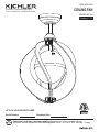
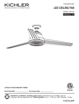
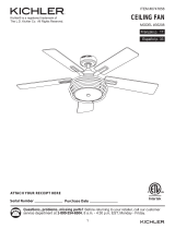
PACKAGE CONTENTS
2
A
Hanging Bracket
Down Rod
Canopy
Canopy Cover
Motor Coupling Cover
Motor Assembly
B
C
D
E
F
1
1
1
1
1
1
PART DESCRIPTION QTY
Upper Fan Blade Assembly
Lower Fan Blade Assembly
Fan Blade
Upper Rectangular Washer
Lower Rectangular Washer
I
H
G
J
K
1
1
5
5
5
PART DESCRIPTION QTY
A
C
E
B
DD
DI
J
K
G
F
H

3
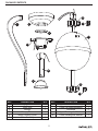
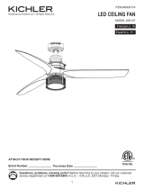
PACKAGE CONTENTS
HARDWARE BAG BALANCE KIT BAG REMOTE CONTROL
Remote Control
Remote Control Holder
Receiver
Battery
Wood Screw
Hanging bracket Screw
Hanging bracket Washer
Wire Connector
Blade Screw
Balance KitBalance Kit
Wood Screw
Wire Connector
Lag Screw
Flat Washer + Spring Washer
SAFETY INFORMATION
Please read and understand this entire manual before attempting to assemble, operate or install the
product.
WARNING:
• Important: When using an existing outlet box, be sure the box is securely attached to the building
structure and can support the full weight of the fan. Failure to do so can result in serious injury or
death.
• Turn off circuit breakers and wall switch to the fan supply wire leads. Warning: Failure to
disconnect power supply prior to installation may result in serious injury or death.
• Warning - Connecting this fan to a light switch (on/off) has been known to cause damage to the
receiver. This fan must be wired to continually receive power. Failure to do so will drastically
reduce the lifespan of this fan.
• Do not install fan on a ceiling with a pitch greater than 20°.
• WARNING – To Reduce The Risk Of Fire, Electric Shock, Or Personal Injury, Mount To Outlet Box
Marked 'Acceptable for Fan Support of 15.9 kg (35 lbs) or less' And Use Mounting Screws
Provided With The Outlet Box and/or Support Directly From Building Structure. Most Outlet Boxes
Commonly Used For The Support of Luminaires Are Not Acceptable For Fan Support And May
Need To Be Replaced. Consult A Qualified Electrician If In Doubt."
• Important: Be sure wiring box is properly grounded or that a ground (green) wire is present.

4
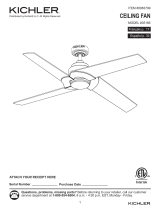
A B C
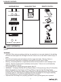
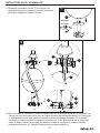
ASSEMBLY INSTRUCTIONS
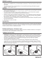
• WARNING-To reduce risk of fire, electric shock, or personal injury, mount to outlet box marked
“Acceptable for Fan Support of 15.9kg (35lbs) or less” and use mounting screws provided with the
outlet box and/or support directly from building structure. Most outlet boxes commonly used for
the support of luminaries are not acceptable for fan support and may need to be replaced.
Consult a qualified electrician if in doubt.
• Warning-Risk of fire, electric shock, or personal injury. Ceiling fans may be either directly
supported from a structural framing member of a building and (see examples in figures A & B) or
may be mounted to an outlet box marked acceptable for fan support of 31.8 kg (70 lbs) to 15.9kg
(35 lbs) (see example in figure C).
CAUTION
PREPARATION
Before beginning assembly of product, make sure all parts are present. Compare parts with package
contents list and diagram. If any part is missing or damaged, do not attempt to assemble the product.
Contact customer service for replacement parts.
Estimated assembly time: 30 minutes to 1 hour.
Tools Required for Assembly (not included): Phillips screwdriver, flathead screwdriver, wire strippers,
electrical tape, ladder, safety glasses, wrench, pliers.
• Read and understand all instructions and illustrations completely before proceeding with assembly
and installation of this fixture.
• If you have any doubts about how to install this lighting fixture, or if the fixture fails to operate
completely, please contact a qualified licensed electrical contractor.
• All parts must be used as indicated in these instructions. Do not substitute any parts, leave parts
out, or use any parts that are worn out or broken. Failure to obey this instruction could invalidate
the UL listing, C.S.A. certification, and/or ETL listing of this fixture.
• This fixture is intended for installation in accordance with the National Electric Code (NEC) and all
local code specifications.
• This fixture is for indoor use only.
WARNING (continued)
• Make sure the installation site you choose allows a minimum of 7 feet from the floor to the end of
the blades.
• To reduce the risk of fire or electrical shock, do not use this fan with any solid state fan speed
device or variable speed control.

ASSEMBLY INSTRUCTIONS
5
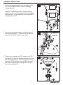
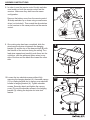
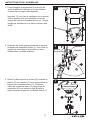
1. Secure the hanging bracket (A) to the ceiling outlet
box using hanging bracket screws and hanging
bracket washers.
Important: If attaching the fan to a sloped ceiling,
make sure open end of mounting bracket is installed
facing the roof. Do not install fan on a ceiling with a
pitch greater than 20°.
2. Loosen the set screws found on coupling on top of
the motor assembly (F). Then remove the hair and
clevis pin that will be used on a later step.
1
Outlet Box
A
3. Place motor coupling cover (E), canopy cover (D),
and canopy (C) over the coupling found on the top of
the motor assembly (F). Feed wires from the motor
assembly (F) through the down rod (B), then insert
the down rod (B) into the coupling found on top of
the motor assembly (F).
2
F
Hair Pin
Clevis Pin
Coupling
3
C
E
B
D
F

ASSEMBLY INSTRUCTIONS
6
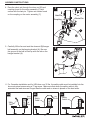
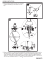
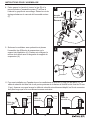
4. Pass the clevis pin through the down rod (B) and
coupling found on the motor assembly (F) and
secure with the hair pin. Tighten set screws found
on the coupling on the motor assembly (F).
5. Carefully lift the fan and seat the downrod (B)/hanger
ball assembly on the hanging bracket (A). Be sure
the groove in the ball is lined up with the tab on the
hanger bracket (A).
5
B
A
Coupling
4
F
Hair Pin
Clevis Pin
6. For Canadian installation and for USA fans over 35 lbs, the safety cable must be installed into the
house structure beams using a 3” lag screw. Make sure that when the safety cable is fully
extended the lead wires are longer than the cable and no stress is placed on the lead wires.
Safety
Cable
Flat
Washer
Spring
Washer
Safety
Cable
Lag
Screw
Safety
Cable
6a 6b 6c

ASSEMBLY INSTRUCTIONS
77
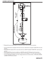
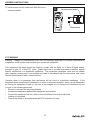
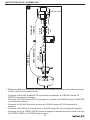
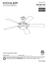
7. Wiring the fan per wiring diagram and securely connect wires with wire connectors:
• Connect WHITE wire marked AC IN N from the fan to WHITE wire marked TO MOTOR N from the
receiver.
• Connect BLACK marked AC IN L wire from the fan to WHITE marked TO MOTOR L wire from the
receiver.
• Connect WHITE wire from the outlet box to WHITE marked AC IN N wire from the receiver.
• Connect BLACK wire from the outlet box to BLACK wire marked AC IN L wire from the receiver.
• Connect GROUND (GREEN) wires from hanger bracket and downrod ball, to GROUND (GREEN
or BARE COPPER) from house.
7
BARE COPPER
(GROUND)
GREEN (BRACKET)
WHITE
(AC INPUT)
WHITE
(NEUTRAL)
BLACK
(AC INPUT)
BLACK
(LIVE)
WHITE
(NEUTRAL)
BLACK
(MOTOR)
BLACK
WHITE
GREEN (DOWN ROD)
WHITE

ASSEMBLY INSTRUCTIONS
8
8
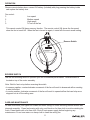
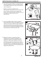
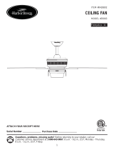
8. In order to use the remote control the dip switches
must match on both the remote control and the
receiver. Make sure they both have the same
configuration.
Remove the battery cover from the remote control.
Slide dip switches up or down using a small screw
driver (not included). Then match the dip switches
on the receiver to the same position as the remote
control.
9. Once wiring step has been completed, slide the
wired remote receiver in between the hanging
bracket (A) and the top of the downrod ball (B) with
the flat side of the receiver facing the ceiling. Turn
lead wires upward and carefully push them into the
outlet box, with the white and green wires to one
side of the box and the black wire toward the other
side.
10. Loosen the two shoulder screws without fully
removing the hanging bracket (A). Assemble canopy
(C) by rotating keyhole slot in canopy over shoulder
screws in hanging bracket (A). Tighten shoulder
screws. Securely attach and tighten the canopy
cover (D) over the shoulder screws in the hanging
bracket (A) utilizing the keyhole slot twist-lock
feature.
9
A
B
10
A
C
D
Shoulder
Screw
Remote Control
Receiver

ASSEMBLY INSTRUCTIONS
9
12. Raise fan blade (I) to the upper fan blade assembly (G) making sure the holes line up on both the
fan blade (I) and the upper fan blade assembly (G). Secure the fan blade by passing two blade
screws through the upper fan blade assembly (G) , fan blade (I) and into the upper rectangular
washer (J). Finially pass one blade screw through the lower fan blade assembly (H), fan blade (I)
and into lower rectangular washer (K). Repeat for remaining fan blades (I).
G
H
12
J
K
I
I
11. Remove shipping retainer from the motor assembly
(F) before assembling the fan blades in the next
step.
11
Shipping
Retainer
F

ASSEMBLY INSTRUCTIONS
10
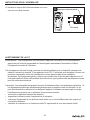
13. Install remote control holder onto wall with wood
screws provided.
13
Remote Control Holder
Wood Screw
FCC WARNING
Warning: Changes or modifications to this unit not expressly approved by the party responsible for
compliance could void the user’s authority to operate the equipment.
This equipment has been tested and found to comply with the limits for a Class B digital device,
pursuant to part 15 of the FCC rules. These limits are to provide reasonable protection against
harmful interference in a residential installation. This equipment generates, uses and can radiate
radio frequency energy and if not installed and used in accordance with the instructions may cause
harmful interference to radio communications.
However, there is no guarantee that interference will not occur in a particular installation. If this
equipment does cause harmful interference to radio or television reception, which can be determined
by turning the equipment off and on, the user is encouraged to try to correct the interference by one
or more of the following measures:
• Reorient or relocate the receiving antenna.
• Increase the separation between the equipment and receiver.
• Connect the equipment into an outlet on a circuit different from that to which the
receiver is connected.
• Consult the dealer or an experienced radio/TV technician for help.

11
CARE AND MAINTENANCE
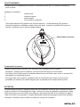
REVERSE SWITCH
At least twice each year tighten all screws and lower canopy to check mounting bracket screws and
downrod assembly. Clean fan housing with only a soft brush or lint free cloth to avoid scratching the
finish. Clean blades with a lint free cloth. Shut off main power supply before beginning any
maintenance. Do not use water or a damp cloth to clean the ceiling fan.
Use the fan reversing switch to optimize your fan for seasonal performance. Reverse switch is
located on top of the motor assembly
Note: Wait for fan to stop before reversing the switch.
• In warmer weather, counterclockwise movement of the fan will result in downward airflow creating
a wind chill effect.
• In cooler weather, clockwise movement of the fan will result in upward airflow that can help move
stagnant hot air off the ceiling area.
Reverse Switch
OPERATION
Remove remote battery door, connect 9V battery (included) with plug pressing the battery inside
and replace the battery door.
Fan control :
3 Low speed
2 Medium speed
1 High speed
0 To turn off the fan
This remote control (M) has a memory function. The remote control (M) stores the fan speed
when the fan is turned off. When the fan is turned on again, it starts with the most recent setting.

12
WARRANTY
Rev. 11-11-16
Printed in China
Kichler offers the following limited lifetime warranty to the Original Purchaser of a Kichler Ceiling Fan:
if the Fan’s motor or motor-related parts should fail due to what Kichler, in its sole discretion,
determines to be a defect in material or workmanship, Kichler will, at its option, either repair or
replace the defective part free of charge.
Except as provided below, for one (1) year following the purchase date, if any part other than the
motor or motor-related parts, including, but not limited to, blades, light kits, downrods, switches,
housing, or finish should fail due to what Kichler, in its sole discretion, determines to be a defect in
material or workmanship, Kichler, at its option, will repair or replace the defective part free of charge.
To replace a product that has a warranted defect, the Original Purchaser shall return any allegedly
defective parts or products to the authorized Kichler distributor that the product was purchased from
with PROOF OF PURCHASE, Original Purchaser’s name and return address and a description of the
claimed product defect.
If any of the warranted products are found by Kichler, in its sole discretion, to be defective, such
products will, at Kichler’s sole option and cost, be replaced, repaired or refunded less an amount
directly attributable to Original Purchaser’s prior use of the product. Kichler will return the repaired or
replaced product prepaid freight. This warranty does not cover labor or other costs or expenses to
remove or install any defective, repaired or replaced product.
The parties hereto expressly agree that Original Purchaser’s sole and exclusive remedy against
Kichler shall be for the repair, replacement or refund of defective products as provided herein. This
warranty extends only to product ownership by the Original Purchaser; is not transferable whether to
heirs, subsequent owners, or otherwise; and is void if the Original Purchaser ceases to own the
product.
This warranty does not apply to any products that have been subjected to misuse, mishandling,
misapplication, connected to voltage at more than 5% above standard North American voltage,
unusual use (including but not limited to use in an environment where the annual average ambient
operating temperature is below 27 or above 95 degrees Fahrenheit), neglect (including but not limited
to improper maintenance), accident, acts of god such as high winds, improper installation or care,
failure to follow the Product’s written instructions for normal use and care, improper packaging of
products returned to Kichler, modification (including but not limited to use of unauthorized parts or
attachments), or adjustment or repair. Significant product exposure to chemicals, harsh cleaners, salt
water or salt air will void any and all warranties on exterior finishes. This warranty only applies when
all components, including transformers, have been provided by Kichler. Substituting another
manufacturer’s product and/or components will render the warranty completely void.
THIS WARRANTY GIVES YOU SPECIFIC LEGAL RIGHTS. YOU MAY ALSO HAVE OTHER
RIGHTS, WHICH VARY FROM STATE TO STATE. SOME STATES DO NOT ALLOW LIMITATIONS
ON HOW LONG AN IMPLIED WARRANTY LASTS OR THE EXCLUSION OR LIMITATION OF
INCIDENTAL OR CONSEQUENTIAL DAMAGES SO THE ABOVE LIMITATIONS OR EXCLUSIONS
MAY NOT APPLY TO YOU.
THE FOREGOING WARRANTY IS IN LIEU OF ALL OTHER WARRANTIES, EXPRESS OR
IMPLIED, INCLUDING THOSE OF MERCHANTABILITY, FITNESS FOR ANY PARTICULAR
PURPOSE OR INFRINGEMENT. ORIGINAL PURCHASER SHALL IN NO EVENT BE ENTITLED
TO, AND KICHLER LIGHTING SHALL NOT BE LIABLE FOR, INDIRECT, SPECIAL, INCIDENTAL
OR CONSEQUENTIAL DAMAGES OF ANY NATURE, INCLUDING, BUT NOT LIMITED TO LOSS
OF PROFIT, PROMOTIONAL AND/OR MANUFACTURING EXPENSES, OVERHEAD, INJURY TO
REPUTATION AND/OR LOSS OF CUSTOMERS.

ARTICLE #0831588
MODÈLE #35162
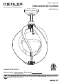
VENTILATEUR DE PLAFOND
13
Kichler® est une marque déposée de
The L.D. Kichler Co. Tous droits réservés.
Des questions, des problèmes, des pièces manquantes? Avant de retourner le produit à
votre détaillant, appelez notre service à la clientèle au 1-800-554-6504, entre 8 h et 16 h 30
(HNE) du lundi au vendredi.
JOIGNEZ VOTRE REÇU ICI
Numéro de série
Date d’achat

14
A
Support de suspension
Tige
Pavillon
Cache du pavillon
Cache raccord du moteur
Ensemble moteur
B
C
D
E
F
1
1
1
1
1
1
Support supérieur de montage des pales
Support inférieur de montage des pales
Pale du ventilateur
Rondelle rectangulaire supérieure
Rondelle rectangulaire inférieure
I
H
G
J
K
1
1
5
5
5
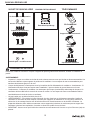
CONTENU DE L’EMBALLAGE
PIÈCE
DESCRIPTION QT
É
PIÈCE
DESCRIPTION QT
É
A
C
E
B
DD
DI
J
K
G
F
H

15
SACHET DE QUINCAILLERIE ENSEMBLE D'ÉQUILIBRAGE TÉLÉCOMMANDE
TÉLÉCOMMANDE
Support de la télécommande
Récepteur
Pile
Vis à bois
Vis du support de suspension
Rondelle du support de suspen
Capuchon de connexion
Vis de pale
Ensemble d'équilibrage
Vis à bois
Capuchon de connexion
Récepteur
QUINCAILLERIE INCLUSE
Tire-fond
Rondelle plate + rondelle ressort
CONSIGNES DE SÉCURITÉ
Veuillez lire et assurez-vous d'avoir compris l’intégralité du présent guide avant d’assembler, d’utiliser ou d’installer ce
produit.
AVERTISSEMENT :
• Important : Lorsque vous utilisez une boîte de sortie existante, assurez-vous que la boîte est fermement attachée à la
structure du bâtiment et peut supporter le poids total du ventilateur. Le non-respect de cette recommandation peut
entraîner des blessures graves ou la mort.
• Coupez les disjoncteurs et l'interrupteur mural qui contrôlent les fils d'alimentation du ventilateur. Avertissement : Si
l'alimentation électrique n'est pas coupée avant l'installation, il peut en résulter de graves blessures ou la mort.
• Avertissement – Connecter ce ventilateur à un interrupteur pour lampe (marche/arrêt) endommage le récepteur. Ce
ventilateur doit être câblé afin de recevoir du courant en continu. Le non-respect de cette recommandation réduira
considérablement la durée de vie de ce ventilateur.
• Ne pas installer sur un plafond incliné à plus de 20°.
• AVERTISSEMENT – Pour réduire le risque d'incendie, de choc électrique ou de blessures corporelles, installez le
ventilateur sur une boîte de sortie marquée "Convient pour supporter un ventilateur de 15,9 kg (35 lb) maximum" et
utilisez les vis de montage fournies avec la boîte de sortie et/ou fixez directement sur la structure du bâtiment. La
plupart des boîtes de sortie utilisées couramment comme support de luminaires ne conviennent pas au support d'un
ventilateur et devront être remplacées. Consultez un électricien qualifié de cas de doute.
• IMPORTANT : Assurez-vous que le boîtier de connexion est correctement mis à la terre ou qu'un fil de terre (vert) est
présent.

16
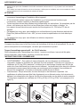
INSTRUCTIONS POUR L'ASSEMBLAGE
A B C
• AVERTISSEMENT – Pour réduire le risque d'incendie, de choc électrique ou de blessures
corporelles, installez le ventilateur sur une boîte de sortie marquée "Convient pour supporter un
ventilateur de 15,9 kg (35 lb) maximum" et utilisez les vis de montage fournies avec la boîte de
sortie et/ou fixez directement sur la structure du bâtiment. La plupart des boîtes de sortie utilisées
couramment comme support de luminaires ne conviennent pas au support d'un ventilateur et
devront être remplacées. Consultez un électricien qualifié de cas de doute.
• Avertissement - Risque d'incendie, de choc électrique ou de blessures corporelles. Les
ventilateurs de plafond peuvent être fixés directement sur un élément porteur de la structure du
bâtiment (voir exemples sur les figures A et B) et/ou être montés sur une boîte de sortie marquée
"Convient pour supporter un ventilateur de 15,9 kg (35 lb) à 31,8 kg (70 lb)" (voir exemple sur la
figure C).
ATTENTION
PRÉPARATION
Avant de commencer l’assemblage du produit, assurez-vous que toutes les pièces sont présentes.
Comparez les pièces avec la liste du contenu de l’emballage et la liste de la quincaillerie. En cas de
pièces manquantes ou endommagées, ne tentez pas d’assembler le produit.
Temps d’assemblage approximatif : de 30 à 60 minutes.
Outils nécessaires pour l’assemblage (non inclus) : tournevis cruciforme, tournevis à tête plate,
pinces à dénuder, ruban isolant, escabeau, lunettes de sécurité.
• Prenez soin de lire et de comprendre l'intégralité des instructions et des illustrations avant de
commencer l’assemblage et l’installation de cet appareil.
• Si vous avez des doutes à propos de l’installation, ou si le luminaire ne fonctionne pas
correctement, veuillez contacter un électricien qualifié agréé.
• Toutes les pièces doivent être utilisées tel qu’indiqué dans ces instructions. Ne remplacez pas les
pièces, n'en laissez pas de côté et ne les utilisez pas si elles sont usées ou brisées. Le
non-respect de ces instructions peut annuler les homologations UL, CSA et/ou ETL de cet
appareil.
• Cet appareil est conçu pour une installation en conformité avec le code électrique national des
États-Unis (National Electric Code - NEC) et avec toutes les spécifications du code électrique
local.
• Cet appareil est conçu pour une utilisation en intérieur uniquement.
AVERTISSEMENT (suite)
• Assurez-vous que le site d'installation choisi offre une hauteur minimum de 2,13 m (7 pi) entre le sol et le dessous
des pales.
• Pour réduire les risques d'incendie ou de choc électrique, n'utilisez pas ce ventilateur avec une commande de vitesse
à semi-conducteurs ou une commande de variation de vitesse.

INSTRUCTIONS POUR L'ASSEMBLAGE
17
2. Desserrez les vis de réglage situées sur le raccord
au-dessus de l'ensemble moteur (F). Puis retirez la
goupille de verrouillage et la clavette qui seront
utilisées dans une étape ultérieure.
1
Boîte de sortie
A
3. Placez le cache raccord du moteur (E), le cache du
pavillon (D) et le pavillon (C) sur le raccord situé au
sommet de l'ensemble moteur (F). Enfilez les
câbles de l'ensemble moteur (F) dans la tige de
suspension (B), puis insérez la tige (B) dans le
raccord situé au sommet de l'ensemble moteur (F).
2
F
Goupille
de verrouillage
Clavette
Raccord
3
C
E
B
D
F
1. Fixez le support de suspension (A) à la boîte de
sortie du plafond à l'aide des vis et des rondelles
fournies avec le support de suspension.
Important : Si vous fixez le ventilateur sur un plafond
incliné, assurez-vous que l'extrémité ouverte du
support de fixation est installée face au toit. Ne pas
installer de ventilateur sur un plafond incliné à plus
de 20°.

INSTRUCTIONS POUR L'ASSEMBLAGE
18
4. Faites passer la clavette à travers la tige (B) et le
raccord situé sur l'ensemble moteur (F) et fixez à
l'aide de la goupille de verrouillage. Serrez les vis de
réglage situées sur le raccord de l'ensemble moteur
(F).
5. Soulevez le ventilateur avec précaution et placez
l'ensemble tige (B)/boule de suspension sur le
support de suspension (A). Prenez soin d'aligner la
rainure de la boule avec la languette du support de
suspension (A).
5
B
A
Raccord
4
F
Goupille
de verrouillage
Clavette
6. Pour une installation au Canada et pour les ventilateurs de plus de 15,8 kg (35 lbs) aux É.-U., le
câble de sécurité doit être fixé à une poutre porteuse de la maison à l'aide d'un tire-fond de 76 mm
(3 po). Assurez-vous que lorsque le câble de sécurité est entièrement déplié, les fils de connexion
sont plus longs que lui et ne subissent aucune contrainte.
Câble de
sécurité
Rondelle
Plate
Rodelle
Ressort
Câble de
sécurité
Tire-
fond
Câble de
sécurité
6a 6b 6c

INSTRUCTIONS POUR L'ASSEMBLAGE
19
7. Réalisez le câblage du ventilateur conformément au schéma de câblage et connectez fermement
les fils à l'aide des connecteurs de fils :
• Connectez le fil BLANC marqué AC IN N provenant du ventilateur au fil BLANC marqué TO
MOTOR N provenant du récepteur.
• Connectez le fil NOIR marqué AC IN L provenant du ventilateur au fil BLANC marqué TO MOTOR
L provenant du récepteur.
• Connectez le fil BLANC de la boîte de sortie au fil BLANC marqué AC IN N provenant du
récepteur.
• Connectez le fil NOIR de la boîte de sortie au fil NOIR marqué AC IN L provenant du récepteur.
• Connectez les fils de TERRE (VERTS) sortant du support de suspension et de la boule de la tige,
à la TERRE (VERTS ou CUIVRE NU) de la maison.
7
CUIVRE NU
(TERRE)
VERT (SUPPORT)
BLANC
(ENTRÉE
CA)
NOIR
(ENTRÉE
CA)
BLANC
(NEUTRE)
NOIR
(PHASE)
BLANC
(NEUTRE)
NOIR
(MOTEUR)
NOIR
BLANC
VERT (Tige)
Boîte de sortie

INSTRUCTIONS POUR L'ASSEMBLAGE
20
8
8. Pour utiliser la télécommande les commutateurs DIP
doivent correspondre à la fois sur la télécommande
et le récepteur. Assurez-vous qu'ils ont tous deux la
même configuration.
Retirez le couvercle de la batterie de la
télécommande. Faites glisser les commutateurs DIP
haut ou le bas à l'aide d'un petit tournevis (non
inclus). Puis correspondre les commutateurs DIP sur
le récepteur à la même position que la
télécommande.
9
A
B
10
A
C
D
Vis à
épaulement
TÉLÉCOMMANDE
Récepteur
9. Une fois le câblage réalisé, insérez le récepteur
distant câblé entre le support de suspension (A) et le
sommet de la boule de suspension (B) en plaçant la
partie plate du récepteur face au plafond. Tournez
les fils vers le haut et poussez-les délicatement dans
la boite de sortie, en plaçant les fils blanc et vert d'un
côté de la boite et le fil noir de l'autre côté.
10.Desserrez les deux vis à épaulement sans
totalement retirer le support de suspension (A).
Assemblez le pavillon (C) en faisant tourner les
fentes en trou de serrure du pavillon sur les vis à
épaulement du support de suspension (A). Serrez
les vis à épaulement. Fixez fermement le cache-trou
du pavillon (D) en le verrouillant par rotation de ses
fentes en trou de serrure sur les vis à épaulement du
support de suspension (A).
La page charge ...
La page charge ...
La page charge ...
La page charge ...
-
 1
1
-
 2
2
-
 3
3
-
 4
4
-
 5
5
-
 6
6
-
 7
7
-
 8
8
-
 9
9
-
 10
10
-
 11
11
-
 12
12
-
 13
13
-
 14
14
-
 15
15
-
 16
16
-
 17
17
-
 18
18
-
 19
19
-
 20
20
-
 21
21
-
 22
22
-
 23
23
-
 24
24


Kichler Lighting 35162 Manuel utilisateur
- Catégorie
- Ventilateurs ménagers
- Taper
- Manuel utilisateur
dans d''autres langues
- English: Kichler Lighting 35162 User manual
Documents connexes
-
 Kichler Lighting 35156 Manuel utilisateur
-
 Kichler Lighting 35163 Manuel utilisateur
-
Kichler 35152 Manuel utilisateur
-
 Kichler Lighting 35157 Manuel utilisateur
-
 Kichler Lighting 35166 Manuel utilisateur
-
 Kichler Lighting 35153 Manuel utilisateur
-
Kichler Lighting 35169 Manuel utilisateur
-
 Kichler Lighting 35208 Manuel utilisateur
-
 Kichler Lighting 35170 Manuel utilisateur
-
 Kichler Lighting 35063 Manuel utilisateur