Samsung LN40A630M1F Manuel utilisateur
- Catégorie
- Téléviseurs LCD
- Taper
- Manuel utilisateur
Ce manuel convient également à

Contact SAMSUNG WORLDWIDE
If you have any questions or comments relating to Samsung products, please contact the SAMSUNG
customer care center.
Contacte con SAMSUNG WORLDWIDE
Si tiene alguna pregunta o comentario referente a nuestros productos, por favor contacte con nuestro Servicio de Atención al
Cliente.
Country
Customer Care Center
Web Site Address
CANADA 1-800-SAMSUNG(726-7864) www.samsung.com/ca
Samsung Electronics Canada Inc., Customer
Service 55 Standish Court Mississauga,
Ontario L5R 4B2 Canada
Samsung Electronique Canada Inc.,
Service à la Clientèle 55 Standish Court
Mississauga, Ontario L5R 4B2 Canada
U.S.A 1-800-SAMSUNG(726-7864) www.samsung.com
Samsung Electronics America, Inc.
105 Challenger Road
Ridgefield Park, NJ 07660-0511
LCD TV
user manual
imagine the possibilities
Thank you for purchasing this Samsung product.
To receive more complete service, please register
your product at
www.samsung.com/global/register
Model Serial No.
BN68-01669A-00
BN68-01669A-00L02-Cover.indd 1 2008-06-13 ¿ÀÈÄ 7:14:56

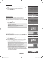
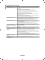
Precautions When Displaying a Still Image
A still image may cause permanent damage to the TV screen
Do not display a still image on the LCD panel for more than 2 hours as it can cause screen image retention. This image
retention is also known as “screen burn”. To avoid such image retention, reduce the degree of brightness and contrast of the
screen when displaying a still image.
Watching the LCD TV in 4:3 format for a long period of time may leave traces of borders displayed on the left,
right and center of the screen caused by the difference of light emission on the screen.
Playing a DVD or a game console may cause a similar effect to the screen.
Damages caused by the above effect are not covered by the Warranty.
Displaying still images from Video games and PC for longer than a certain period of time may produce partial after-images.
To prevent this effect, reduce the ‘brightness’ and ‘contrast’ when displaying still images.
•
•
•
© 2008 Samsung Electronics Co., Ltd. All rights reserved.
Important Warranty Information Regarding Television Format Viewing
Wide screen format LCD Displays (16:9, the aspect ratio of the screen width to height) are primarily designed to view wide screen format
full-motion video. The images displayed on them should primarily be in the wide screen 16:9 ratio format, or expanded to ll the screen if
your model offers this feature and the images are constantly moving. Displaying stationary graphics and images on screen, such as the dark
sidebars on nonexpanded standard format television video and programming, should be limited to no more than 5% of the total television
viewing per week.
Additionally, viewing other stationary images and text such as stock market reports, video game displays, station logos, web sites or computer
graphics and patterns, should be limited as described above for all televisions. Displaying stationary images that exceed the above guidelines
can cause uneven aging of LCD Displays that leave subtle, but permanent burned-in ghost images in the LCD picture. To avoid this, vary the
programming and images, and primarily display full screen moving images, not stationary patterns or dark bars.
On LCD models that offer picture sizing features, use these controls to view different formats as a full screen picture.
Be careful in the selection and duration of television formats used for viewing. Uneven LCD aging as a result of format selection and use, as
well as burned-in images, are not covered by your Samsung limited warranty.
SAMSUNG ELECTRONICS NORTH AMERICAN LIMITED WARRANTY STATEMENT
Subject to the requirements, conditions, exclusions and limitations of the original Limited Warranty supplied with Samsung Electronics
(SAMSUNG) products, and the requirements, conditions, exclusions and limitations contained herein, SAMSUNG will additionally provide
Warranty Repair Service in the United States on SAMSUNG products purchased in Canada, and in Canada on SAMSUNG products
purchased in the United States, for the warranty period originally specied, and to the Original Purchaser only.
The above described warranty repairs must be performed by a SAMSUNG Authorized Service Center. Along with this Statement, the
Original Limited Warranty Statement and a dated Bill of Sale as Proof of Purchase must be presented to the Service Center. Transportation
to and from the Service Center is the responsibility of the purchaser.
Conditions covered are limited only to manufacturing defects in material or workmanship, and only those encountered in normal use of the
product.
Excluded, but not limited to, are any originally specied provisions for, in-home or on-s
ite services, minimum or maximum repair
times,
exchanges or replacements, accessories, options, upgrades, or consumables.
For the location of a SAMSUNG Authorized Service Center, please call toll-free:
In the United States : 1-800-SAMSUNG (1-800-726-7864) In Canada : 1-800-SAMSUNG
See the warranty card for more information on warranty terms.
➣
BN68-01669A-00Eng.indb 1 2008-06-13 ¿ÀÈÄ 7:12:35

General Information
List of Features ..................................................................2
Accessories .......................................................................2
Viewing the Control Panel .................................................3
Viewing the Connection Panel ...........................................4
Remote Control .................................................................5
Installing Batteries in the Remote Control .........................6
Connections
Connecting VHF and UHF Antennas .................................6
Connecting Cable TV ........................................................7
Connecting a DVD Player or Cable Box/Satellite receiver
(Set-Top Box) via HDMI .....................................................8
Connecting a DVD Player or Cable Box/Satellite receiver
(Set-Top Box) via DVI ........................................................8
Connecting a DVD Player or Cable Box/Satellite receiver
(Set-Top Box) via Component cables ................................9
Connecting a Camcorder ...................................................9
Connecting a VCR ...........................................................10
Connecting a Digital Audio System .................................11
Connecting an Amplier/DVD Home Theater ..................11
Connecting a PC .............................................................11
Operation
Turning the TV On and Off ..............................................12
Plug & Play Feature .........................................................12
Changing Channels .........................................................13
Adjusting the Volume .......................................................14
Viewing the Display .........................................................14
Viewing the Menus ..........................................................14
Using the TOOLS Button .................................................15
Memorizing the Channels ................................................15
To Select the Source .......................................................17
To Edit the Input Source Name ........................................17
Picture Control
Changing the Picture Standard .......................................18
Customizing the Picture Settings .....................................18
Adjusting the Detailed Settings ........................................19
Resetting the Picture Settings to the Factory Defaults ....22
Conguring Picture Options .............................................23
Viewing Picture-in-Picture ...............................................27
Sound Control
Changing the Sound Standard ........................................29
Customizing the Sound ...................................................29
Setting the TruSurround XT .............................................30
Choosing Preferred Language ........................................31
Choosing a Multi-Channel Sound (MTS) track ................31
Automatic Volume Control ...............................................32
Selecting the Speaker .....................................................32
Listening to the Sound of the Sub (PIP) Picture ..............33
Resetting the Sound Settings to the Factory Defaults .....33
Connecting Headphones (Sold separately) .....................33
Channel Control
Managing Channels .........................................................34
Clearing Scrambled Channels - Digital ............................41
Fine Tuning Analog Channels ..........................................41
Checking the Digital-Signal Strength ...............................42
■
■
■
■
■
■
■
■
■
■
■
■
■
■
■
■
■
■
■
■
■
■
■
■
■
■
■
■
■
■
■
■
■
■
■
■
■
■
■
■
■
■
■
■
■
■
PC Display
Using Your TV as a Computer (PC) Display ....................43
Display Modes .................................................................43
Setting up the TV with your PC .......................................44
Time Setting
Setting the Clock .............................................................46
Function Description
Selecting a Menu Language ............................................50
Using the V-Chip ..............................................................50
Viewing Closed Captions (On-Screen Text Messages)
- Analog ...........................................................................57
Viewing Closed Captions (On-Screen Text Messages)
- Digital ............................................................................58
Adjusting the TV On/Off Melody Sound ...........................59
Setting the Entertainment mode ......................................59
Using the Energy Saving Feature ....................................60
Upgrading the Software ...................................................60
Self diagnosis .................................................................61
WISELINK
Using the WISELINK Function ........................................62
Using the Photo List ........................................................63
Sorting Photo List ............................................................65
Viewing a Photo or Slide Show ......................................69
Using the Music List ........................................................73
Sorting Music List ............................................................74
Playing a Music File .........................................................78
Using the Setup Menu .....................................................80
About Anynet
+
What is Anynet
+
?.............................................................81
Connecting Anynet
+
Devices...........................................81
Setting Up Anynet
+
.........................................................82
Scanning and Switching between Anynet
+
Devices ........83
Recording ........................................................................84
Listening through a Receiver (Home theater) ..................84
Troubleshooting for Anynet
+
...........................................85
Appendix
Troubleshooting ...............................................................86
Installing the Stand ..........................................................88
Disconnecting the Stand ..................................................88
Auto Wall-Mount Adjustment (Sold separately) ..............89
Wall Mount Kit Specications (VESA) .............................90
Using the Anti-Theft Kensington Lock .............................91
Securing the TV to the Wall .............................................92
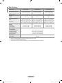
Specications ..................................................................93
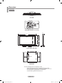
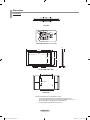
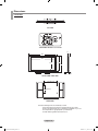
Dimensions ......................................................................94
■
■
■
■
■
■
■
■
■
■
■
■
■
■
■
■
■
■
■
■
■
■
■
■
■
■
■
■
■
■
■
■
■
■
■
■
■
English - 1
English
Contents
Symbol Press Note One-Touch Button
BN68-01669A-00Eng.indb 1 2008-06-13 ¿ÀÈÄ 7:12:36

English - 2
List of Features
Adjustable picture settings that can be stored in the TV’s memory.
Automatic timer to turn the TV on and off.
A special sleep timer.
Excellent Digital Interface & Networking :
With a built-in HD digital tuner, non-subscription HD broadcasts can be viewed with no Cable Box/Satellite receiver
(Set-Top Box) needed.
You can listen to music les and view pictures on USB Mass Storage Class (MSC) devices.
HDMI/DVI connection of your PC to this TV.
Excellent Picture Quality
- DNIe technology provides life-like clear images.
SRS TruSurround XT
- SRS TruSurround XT provides a virtual surround system.
•
•
•
•
•
•
•
•
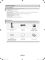
Accessories
Please make sure the following items are included with your LCD TV. If any items are missing, contact your dealer.
Remote Control & Batteries (AAA x 2)
(BN59-00673A)
Power Cord
(3903-000144)
Warranty Card /
Registration Card /
Safety Guide Manual
(Not available in all locations)
Cover-Bottom
(LN40A630M1F: BN63-04783A)
(LN46A630M1F: BN63-04784A)
(LN52A630M1F: BN63-04854A)
Cleaning Cloth
(BN63-01798B)
Owner’s Instructions
General Information
BN68-01669A-00Eng.indb 2 2008-06-13 ¿ÀÈÄ 7:12:36

English - 3
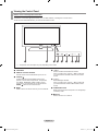
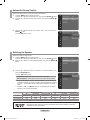
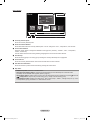
Viewing the Control Panel
Buttons on the Lower-Right Part of the Panel
The buttons on the lower-right panel control your TV’s basic features, including the on-screen menu.
To use the more advanced features, you must use the remote control.
88
1
2
3
4
5
7 6
88
4
1
2
3
6
5
12345677 8
7
12345677 8
87654311 2
The product color and shape may vary depending on the model.
➣
1
SPEAKERS
2
REMOTE CONTROL SENSOR
Aim the remote control towards this spot on the TV.
3
SOURCE
Toggles between all the available input sources
(TV, AV1, AV2, S-Video, Component1, Component2,
PC, HDMI1, HDMI2/DVI, HDMI3, USB). In the on-
screen menu, use this button as you would use the
ENTER button on the remote control.
4
MENU
Press to see an on-screen menu of your TV’s features.
5
– VOL +
Press to increase or decrease the volume.
In the on-screen menu, use the – VOL + buttons as
you would use the ◄ and ► buttons on the remote
control.
6
CH
Press to change channels.
In the on-screen menu, use the CH buttons as
you would use the ▲ and ▼ buttons on the remote
control.
7
POWER INDICATOR
Blinks and turns off when the power is on and lights up
in stand-by mode.
8
(Power)
Press to turn the TV on and off.
BN68-01669A-00Eng.indb 3 2008-06-13 ¿ÀÈÄ 7:12:37

English - 4
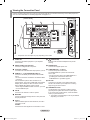
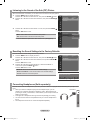
Viewing the Connection Panel
Use the connection panel jacks to connect A/V components that will be connected continuously, such as DVD players or a
VCR. For more information on connecting equipment, see pages 6~11.
[TV Side Panel][TV Rear Panel]
The product color and shape may vary depending on the model.
➣
1
AUDIO OUT
Connects to the audio input jacks on your Amplier/
Home theater.
2
DIGITAL AUDIO OUT (OPTICAL)
Connects to a Digital Audio component.
3
PC IN [PC] / [AUDIO]
Connects to the video and audio output jacks on your PC.
4
HDMI IN 1, 2, 3 / DVI IN(HDMI2)[R-AUDIO-L]
Connects to the HDMI jack of a device with an HDMI
output.
- No sound connection is needed for an HDMI to HDMI
connection.
Use the HDMI IN 2 jack for DVI connection to an
external device. Use a DVI to HDMI cable or DVI-HDMI
adapter (DVI to HDMI) for video connection and the
DVI IN (HDMI2) [R-AUDIO-L] jacks for audio.
- When using an HDMI/DVI cable connection, you must
use the HDMI IN 2 jack.
5
ANT IN
Connects to an antenna or cable TV system.
6
WISELINK
Connect a USB mass storage device to view photo les
and play audio les.
7
AV IN 2
Video and audio inputs for external devices, such as a
camcorder or VCR.
S-VIDEO
Connects an S-Video signal from a camcorder or VCR.
8
(HEADPHONE)
Connects a set of external headphones for private
listening.
9
POWER INPUT
Connects the supplied power cord.
0
COMPONENT IN 1, 2 / AV IN 1
Connects Component video/audio.
The COMPONENT IN 1 jack is also used as the
AV IN 1 jack.
- Connect the video cable to the COMPONENT IN 1
[Y/VIDEO] jack and the audio cable to the
COMPONENT IN 1 [R-AUDIO-L] jacks.
!
EX-LINK
Connect this to the jack on the optional wall mount
bracket. This will allow you to adjust the TV viewing
angle using your remote control.
@
KENSINGTON LOCK
The Kensington Lock (optional) is a device used to
physically x the system when used in a public place.
If you want to use a locking device, contact the dealer
where you purchased the TV.
The location of the Kensington Lock may be different
depending on its model.
➣
BN68-01669A-00Eng.indb 4 2008-06-13 ¿ÀÈÄ 7:12:37

English - 5
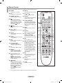
Remote Control
You can use the remote control up to a distance of about 23 feet from the TV.
1
POWER
Turns the TV on and off.
2
TV
Selects the TV mode directly.
3
NUMERIC BUTTONS
Press to change the channel.
4
Press to select additional
channels (digital and analog)
being broadcast by the same
station. For example, to select
channel “54-3”, press “54”,
then press “ ” and “3”.
5
(MUTE)
Press to temporarily cut off the
sound.
6
VOL – / VOL +
Press to increase or decrease
the volume.
7
CH LIST
Used to display Channel Lists
on the screen.
8
TOOLS
Use to quickly select frequently
used functions.
9
INFO
Press to display information on
the TV screen.
0
COLOR BUTTONS
Use these buttons in the
Channel list, WISELINK, etc.
!
CC
Controls the caption decoder.
@
E.MODE
Press to select the preset
display and sound modes for
sports, cinema and games.
#
Use these buttons in the
DMA, WISELINK and Anynet
+
modes.
( : This remote can be
used to control recording on
Samsung recorders with the
Anynet
+
feature)
$
ON/OFF
Press to backlight the buttons
on the remote. This function is
convenient for using at night or
when the room is dark. (Using
the remote control with the
ON/OFF light button set
to On will reduce the battery
usage time.)
%
PRE-CH
Tunes to the previous channel.
^
CH / CH
Press to change channels.
&
SOURCE
Press to display and select the
available video sources.
*
W.LINK (WISELINK)
This function enables you to
view and play photo and music
les from an external device.
(Refer to pages 63 (Photo) and
73 (Music))
(
MENU
Displays the main on-screen
menu.
)
RETURN
Returns to the previous menu.
a
UP▲/DOWN▼/LEFT◄/
RIGHT►/ENTER
Use to select on-screen menu
items and change menu values.
b
EXIT
Press to exit the menu.
c
DMA (Digital Media Adapter)
Use this when connecting
a SAMSUNG DMA device
through an HDMI interface and
switching to DMA mode.
For more information on the
operating procedures, refer to
the user manual of the DMA.
This button is available when
“Anynet
+
(HDMI-CEC)” is “On”.
(see page 82)
d
MTS
Press to choose stereo, mono
or Separate Audio Program
(SAP broadcast).
e
FAV.CH
Press to switch to your favorite
channels.
f
P.SIZE
Picture size selection.
The performance of the remote control may be affected by bright light.
➣
BN68-01669A-00Eng.indb 5 2008-06-13 ¿ÀÈÄ 7:12:38

English - 6
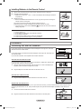
Installing Batteries in the Remote Control
1. Lift the cover at the back of the remote control upward as shown in the gure.
2. Install two AAA size batteries.
Make sure to match the “+” and “–” ends of the batteries with the diagram inside the
compartment.
3. Replace the cover.
Remove the batteries and store them in a cool, dry place if you won’t be using the
remote control for a long time.
The remote control can be used up to about 23 feet from the TV.
(Assuming typical TV usage, the batteries should last for about one year.)
Using the remote control with the ON/OFF light button set to On will reduce the
battery usage time.
If the remote control doesn’t work, check the following:
1. Is the TV power on?
2. Are the plus and minus ends of the batteries reversed?
3. Are the batteries drained?
4. Is there a power outage or is the power cord unplugged?
5. Is there a special uorescent light or neon sign nearby?
➣
➣
➣
➣
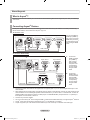
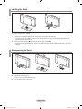
Connecting VHF and UHF Antennas
If your antenna has a set of leads that look like the diagram to the right, see “Antennas
with 300 Ω Flat Twin Leads” below.
If your antenna has one lead that looks like the diagram to the right, see “Antennas with
75 Ω Round Leads”.
If you have two antennas, see “Separate VHF and UHF Antennas”.
Antennaswith300ΩFlatTwinLeads
If you are using an off-air antenna (such as a roof antenna or “rabbit ears”) that has 300
Ω twin at leads, follow the directions below.
1. Place the wires from the twin leads under the screws on a 300-75 Ω adapter (not
supplied). Use a screwdriver to tighten the screws.
2. Plug the adaptor into the ANT IN terminal on the back of the TV.
Antennaswith75ΩRoundLeads
1. Plug the antenna lead into the ANT IN terminal on the back of the TV.
Separate VHF and UHF Antennas
If you have two separate antennas for your TV (one VHF and one UHF), you must combine the two antenna signals before
connecting the antennas to the TV. This procedure requires an optional combiner-adaptor (available at most electronics
shops).
1. Connect both antenna leads to the combiner.
2. Plug the combiner into the ANT IN terminal on the bottom of the rear panel.
Connections
ANT IN
ANT IN
UHF
VHF
ANT IN
UHF
VHF
BN68-01669A-00Eng.indb 6 2008-06-13 ¿ÀÈÄ 7:12:38

English - 7
Connecting Cable TV
To connect to a cable TV system, follow the instructions below.
Cable without a Cable Box
1. Plug the incoming cable into the ANT IN terminal on the back of the TV.
Because this TV is cable-ready, you do not need a cable box to view
unscrambled cable channels.
Connecting to a Cable Box that Descrambles All Channels
1. Find the cable that is connected to the ANT OUT terminal on your cable box.
This terminal might be labeled “ANT OUT”, “VHF OUT” or simply, “OUT”.
2. Connect the other end of this cable to the ANT IN terminal on the back of the TV.
Connecting to a Cable Box that Descrambles Some Channels
If your cable box descrambles only some channels (such as premium channels), follow the instructions below. You will need
a two-way splitter, an RF (A/B) switch and four lengths of RF cable. (These items are available at most electronics stores.)
1. Find and disconnect the cable that is
connected to the ANT IN terminal on
your cable box.
This terminal might be labeled
“ANT IN”, “VHF IN” or simply, “IN”.
2. Connect this cable to a two-way
splitter.
3. Connect an RF cable between the
OUTPUT terminal on the splitter and
the IN terminal on the cable box.
4. Connect an RF cable between the
ANT OUT terminal on the cable box
and the B–IN terminal on the RF(A/B)
switch.
5. Connect another cable between the
other OUT terminal on the splitter and
the A–IN terminal on the RF (A/B)
switch.
6. Connect the last RF cable between
the OUT terminal on the RF (A/B)
switch and the ANT IN terminal on the
rear of the TV.
After you have made this connection, set the A/B switch to the “A” position for normal viewing. Set the A/B switch to the “B”
position to view scrambled channels. (When you set the A/B switch to “B”, you will need to tune your TV to the cable box’s
output channel, which is usually channel 3 or 4.)
➣
➣
➣
ANT OUT
ANT IN
ANT IN
ANT IN
Splitter
Incoming
cable
Splitter
Cable Box
Incoming
cable
Splitter
Cable Box
RF (A/B)
Switch
Incoming
cable
ANT IN
Splitter
Cable Box
Incoming
cable
RF (A/B)
Switch
Splitter
Cable Box
Incoming
cable
TV Rear
RF (A/B)
Switch
ANT IN
BN68-01669A-00Eng.indb 7 2008-06-13 ¿ÀÈÄ 7:12:39

English - 8
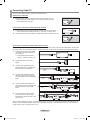
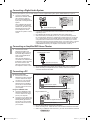
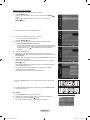
Connecting a DVD Player or Cable Box/Satellite receiver (Set-Top Box) via HDMI
This connection can only be made if there is an HDMI Output connector on the external device.
1. Connect an HDMI Cable
between the HDMI IN
(1, 2 or 3) jack on the
TV and the HDMI jack
on the DVD Player or
Cable Box/Satellite
receiver (Set-Top Box).
What is HDMI?
• HDMI(High-Denition Multimedia Interface), is an interface that enables the
transmission of digital audio and video signals using a single cable.
• The difference between HDMI and DVI is that the HDMI device is smaller in size and
has the HDCP (High Bandwidth Digital Copy Protection) coding feature installed. DVI
also requires a separate audio connection (see below).
Each DVD Player or Cable Box/Satellite receiver (Set-Top Box) has a different back
panel conguration.
The TV may not output sound and pictures may be displayed with abnormal color when
DVD players/Cable Boxes/Satellite receivers supporting HDMI versions older than 1.3
are connected. When connecting an older HDMI cable and there is no sound, connect
the HDMI cable to the HDMI IN 2 jack and the audio cables to the DVI IN (HDMI2)
[R-AUDIO-L] jacks on the back of the TV. If this happens, contact the company that
provided the DVD player/Cable Box/Satellite receiver to conrm the HDMI version, then
request an upgrade.
HDMI cables that are not 1.3 may cause annoying icker or no screen display.
➣
➣
➣
➣
or
DVD Player or Cable Box/Satellite receiver
(Set-Top Box) Rear Panel
TV Rear Panel
HDMI Cable (Not supplied)
TV Side Panel
Connecting a DVD Player or Cable Box/Satellite receiver (Set-Top Box) via DVI
This connection can only be made if there is a DVI Output connector on the external device.
1. Connect a DVI to HDMI
Cable or DVI-HDMI
Adapter between the
HDMI IN 2 jack on the
TV and the DVI jack
on the DVD Player or
Cable Box/Satellite
receiver (Set-Top Box).
2. Connect Audio Cables
between the DVI IN
(HDMI 2) [R-AUDIO-L]
jack on the TV and the
DVD Player or Cable
Box/Satellite receiver
(Set-Top Box).
Each DVD Player or Cable Box/Satellite receiver (Set-Top Box) has a different back
panel conguration.
When connecting a DVD Player or Cable Box/Satellite receiver (Set-Top Box), match
the color of the connection terminal to the cable.
When using an HDMI/DVI cable connection, you must use the HDMI IN 2 jack.
➣
➣
➣
TV Rear Panel
DVD Player or Cable Box/
Satellite receiver (Set-Top Box)
Audio Cable (Not supplied)
2
DVI to HDMI Cable (Not supplied)
1
BN68-01669A-00Eng.indb 8 2008-06-13 ¿ÀÈÄ 7:12:40

English - 9
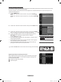
or
TV Side Panel
Camcorder
S-Video Cable (Not supplied)
1
Audio Cable
(Not supplied)
2
Video Cable (Not supplied)
1
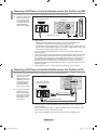
Connecting a Camcorder
The side panel jacks on your TV make it easy to connect a camcorder to your TV.
They allow you to view the camcorder tapes without using a VCR.
1. Connect a Video Cable
(or S-Video Cable)
between the AV IN 2
[VIDEO] (or S-VIDEO)
jack on the TV and the
VIDEO OUT jack on the
camcorder.
2. Connect Audio Cables
between the AV IN 2
[R-AUDIO-L] jacks on
the TV and the AUDIO
OUT jacks on the
camcorder.
Each Camcorder has a different back panel conguration.
When connecting a Camcorder, match the color of the connection terminal to the cable.
➣
➣
Connecting a DVD Player or Cable Box/Satellite receiver (Set-Top Box) via Component cables
The rear panel jacks on your TV make it easy to connect a DVD Player or Cable Box/Satellite receiver (Set-Top Box) to your TV.
1. Connect a Component
Cable between the
COMPONENT IN
(1 or 2) [Y, PB, PR]
jacks on the TV and the
COMPONENT
[Y, PB, PR] jacks on the
DVD Player or Cable
Box/Satellite receiver
(Set-Top Box).
2. Connect Audio
Cables between the
COMPONENT IN(1 or
2) [R-AUDIO-L] jacks on
the TV and the AUDIO
OUT jacks on the
DVD Player or Cable
Box/Satellite receiver
(Set-Top Box).
Component video separates the video into Y (Luminance (brightness)), Pb (Blue) and
Pr (Red) for enhanced video quality.
Be sure to match the component video and audio connections.
For example, if connecting a Component video cable to COMPONENT IN 1, connect
the audio cable to COMPONENT IN 1 also.
Each DVD Player or Cable Box/Satellite receiver (Set-Top Box) has a different back
panel conguration.
When connecting a DVD Player or Cable Box/Satellite receiver (Set-Top Box), match
the color of the connection terminal to the cable.
➣
➣
➣
TV Rear Panel
DVD Player or Cable Box /
Satellite receiver (Set-Top Box)
Audio Cable
(Not supplied)
2
Component Cable (Not supplied)
1
BN68-01669A-00Eng.indb 9 2008-06-13 ¿ÀÈÄ 7:12:40

English - 10
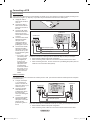
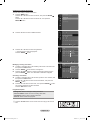
Connecting a VCR
Video Connection
These instructions assume that you have already connected your TV to an antenna or a cable TV system (according to the
instructions on pages 6~7). Skip step 1 if you have not yet connected to an antenna or a cable system.
1. Unplug the cable or
antenna from the back
of the TV.
2. Connect the cable or
antenna to the ANT IN
terminal on the back of
the VCR.
3. Connect an RF Cable
between the ANT OUT
terminal on the VCR
and the ANT IN terminal
on the TV.
4. Connect a Video Cable
between the VIDEO
OUT jack on the
VCR and the AV IN 1
[Y/VIDEO] or AV IN 2
[VIDEO] jack on the TV.
5. Connect Audio Cables
between the AUDIO
OUT jacks on the VCR
and the AV IN 1 (or AV
IN 2) [R-AUDIO-L] jacks
on the TV.
If you have a “mono”
(non-stereo) VCR,
use a Y-connector
(not supplied) to
connect to the
right and left audio
input jacks of the
TV. Alternatively,
connect the cable to
the “R” jack. If your
VCR is stereo, you
must connect two
cables.
➣
ANT IN
Follow the instructions in “Viewing a VCR or Camcorder Tape” to view your VCR tape.
Each VCR has a different back panel conguration.
When connecting a VCR, match the color of the connection terminal to the cable.
When connecting to AV IN 1, the color of the AV IN 1 [Y/VIDEO] jack (Green) does not
match the color of the video cable (Yellow).
➣
➣
➣
S-Video Connection
Your Samsung TV can be connected to an S-Video jack on a VCR. (This connection delivers a better picture as compared
to a standard VCR.)
1. To begin, follow steps
1–3 in the previous
section to connect the
antenna or cable to your
VCR and your TV.
2. Connect an S-Video
Cable between the
S-VIDEO OUT jack on
the VCR and the
AV IN 2 [S-VIDEO] jack
on the TV.
3. Connect Audio Cables
between the AUDIO
OUT jacks on the VCR
and the AV IN 2
[R-AUDIO-L] jacks on
the TV.
An S-Video cable may be included with a VCR. (If not, check your local electronics store.)
Each VCR has a different back panel conguration.
When connecting a VCR, match the color of the connection terminal to the cable.
➣
➣
VCR Rear Panel
TV Rear Panel
TV Side Panel
RF Cable (Not supplied)
3
Video Cable (Not supplied)
4
Audio Cable (Not supplied)
5
VCR Rear Panel
TV Rear Panel
TV Side Panel
Audio Cable (Not supplied)
3
S-Video Cable (Not supplied)
2
RF Cable (Not supplied)
1
BN68-01669A-00Eng.indb 10 2008-06-13 ¿ÀÈÄ 7:12:41

English - 11
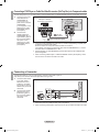
Connecting a Digital Audio System
The rear panel jacks on your TV make it easy to connect a Digital Audio System (Home theater/Receiver) to your TV.
1. Connect an Optical Cable
between the “DIGITAL AUDIO
OUT (OPTICAL)” jacks on
the TV and the Digital Audio
Input jacks on the Digital Audio
System.
When a Digital Audio System
is connected to the “DIGITAL
AUDIO OUT (OPTICAL)” jack:
Decrease the volume of the
TV and adjust the volume
level with the system’s volume
control.
5.1CH audio is possible when the TV is connected to an external device
supporting 5.1CH.
Each Digital Audio System has a different back panel conguration.
When the receiver (home theater) is set to On, you can hear sound output from
the TV’s Optical jack. When the TV is displaying a DTV(air) signal, the TV will send
out 5.1 channel sound to the Home theater receiver. When the source is a digital
component such as a DVD and is connected to the TV via HDMI, only 2 channel
sound will be heard from the Home Theater receiver. If you want to hear 5.1 channel
audio, connect the DIGITAL AUDIO OUT (OPTICAL) jack on the DVD player or
Cable/Satellite Box directly to an Amplier or Home Theater, not the TV.
➣
➣
➣
TV Rear Panel
Digital Audio System
Optical Cable (Not supplied)
ConnectinganAmplier/DVDHomeTheater
1. Connect Audio Cables
between the AUDIO OUT
[R-AUDIO-L] jacks on the TV
and AUDIO IN [R-AUDIO-L]
jacks on the Amplier/DVD
Home Theater.
When an audio amplier is
connected to the “AUDIO OUT
[R-AUDIO-L]” jacks: Decrease
the volume of the TV and
adjust the volume level with
the Amplier’s volume control.
Each Amplier/DVD Home Theater has a different back panel conguration.
When connecting an Amplier/DVD Home Theater, match the color of the
connection terminal to the cable.
➣
➣
TV Rear Panel
Amplier/DVDHomeTheater
Audio Cable (Not supplied)
Connecting a PC
Using the D-Sub Cable
1. Connect a D-Sub Cable
between PC IN [PC] connector
on the TV and the PC output
connector on your computer.
2. Connect a PC Audio Cable
between the PC IN [AUDIO]
jack on the TV and the Audio
Out jack of the sound card on
your computer.
Using the HDMI/DVI Cable
1. Connect an HDMI/DVI cable
between the HDMI IN 2 jack
on the TV and the PC output
jack on your computer.
2. Connect a 3.5 mm Stereo mini-
plug/2RCA Cable between the
DVI IN(HDMI2) [R-AUDIO-L]
jack on the TV and the Audio
Out jack of the sound card on
your computer.
Each PC has a different back panel conguration.
When connecting a PC, match the color of the connection terminal to the cable.
When using an HDMI/DVI cable connection, you must use the HDMI IN 2 terminal.
➣
➣
➣
TV Rear Panel
Using the D-Sub Cable
Using the HDMI/DVI Cable
TV Rear Panel
D-Sub Cable (Not supplied)
1
PC Audio Cable (Not supplied)
2
3.5 mm Stereo mini-plug/2RCA Cable (Not supplied)
2
HDMI/DVI Cable (Not supplied)
1
PC
PC
BN68-01669A-00Eng.indb 11 2008-06-13 ¿ÀÈÄ 7:12:42

English - 12
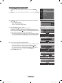
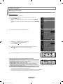
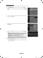
Turning the TV On and Off
Press the POWER button on the remote control.
You can also use the POWER button on the TV.
Operation
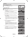
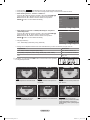
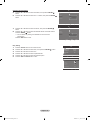
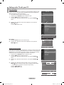
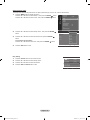
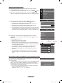
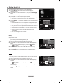
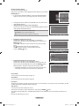
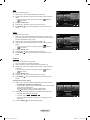
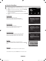
Plug & Play Feature
When the TV is initially powered on, basic settings proceed automatically and
subsequently.
1. Press the POWER button on the remote control.
The message “Menu Language, Store Demo, Channels, and Time will be
set.” is displayed.
Press the
ENTER button, then “Select Language of the OSD.” menu
is automatically displayed. Press the ENTER button.
2. Press the ▲ or ▼ button to select language, then press the ENTER
button. The message “Select ‘Home Use’ when installing this TV in your
home.” is displayed.
3. Press the ◄ or ► button to select “Store Demo” or “Home Use”, then
press the ENTER button. The message “Select the Antenna source to
memorize.” is displayed.
We recommend setting the TV to “Home Use” mode for the best picture in
your home environment.
“Store Demo” mode is only intended for use in retail environments.
If the unit is accidentally set to “Store Demo” mode and you want to return
to “Home Use” (Standard): Press the Volume button on the TV. When the
volume OSD is displayed, press and hold the MENU button on the TV for
5 seconds.
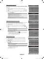
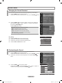
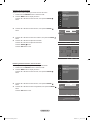
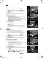
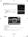
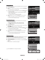
4. Press the ▲ or ▼ button to memorize the channels of the selected
connection. Press the ENTER button to select “Start”.
Air: “Air” antenna signal.
Cable: “Cable” antenna signal.
Auto: “Air” and “Cable” antenna signals.
In Cable mode, you can select the correct signal source among STD,
HRC, and IRC by pressing the ▲, ▼, ◄ or ► button, then press the
ENTER button. If you have Digital cable, select the cable system
signal source for both Analog and Digital. Contact your local cable
company to identify the type of cable system that exists in your particular
area.
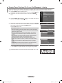
5. The TV will begin memorizing all of the available channels.
To stop the search before it has nished, press the ENTER button with
“Stop” selected.
After all the available channels are stored, it starts to remove scrambled
channels (see page 41). And then, the Auto program menu reappears.
Press the ENTER button when channel memorization is complete.
The message “Set the Clock Mode.” is displayed.
➣
➣
➣
➣
➣
➣
Plug & Play
Select ‘Home Use’ when installing this TV in your
home.
Home Use
Store Demo
EnterMove
Plug & Play
Select Language of the OSD.
Menu Language : English
EnterMove
English
Español
Français
Plug & Play
Menu Language, Store Demo, Channels, and Time will
be set.
OK
Enter
Plug & Play
Select the Antenna source to memorize.
Air
Cable
Auto
Start
SkipEnterMove
Start
Start
Plug & Play
Auto Program in Progress.
Stop
Cable 38
50%
DTV Air : 02 Air : 11
DTV Cable : 23 Cable : 21
SkipEnter
Start
Plug & Play
Selects the cable system.
Analog
Digital
HRC IRC
HRC IRCSTD
STD
SkipEnterMove
Plug & Play
Removing scrambled channel.
Stop
DTV Cable 41
77%
DTV Air : 05 Air : 12
DTV Cable : 25 Cable : 32
Skip
Enter
Plug & Play
Auto Program is completed.
119 channels are memorized.
DTV Air : 05 Air : 24
DTV Cable : 10 Cable : 80
OK
SkipEnter
BN68-01669A-00Eng.indb 12 2008-06-13 ¿ÀÈÄ 7:12:43

English - 13
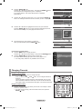
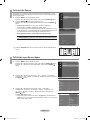
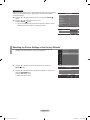
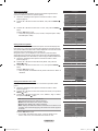
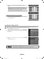
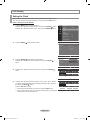
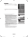
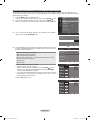
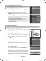
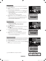
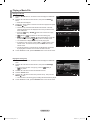
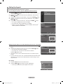
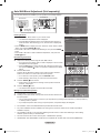
6. Press the ENTER button.
Press the ▲ or ▼ button to select “Auto”, then Press the ENTER button.
The message “Set to daylight saving time.” is displayed.
If you select “Manual”, “Set current date and time” is displayed.
(See page 46)
7. Press the ▲ or ▼ button to select “Off” or “On”, then press the ENTER
button. The message “Select the time zone in which you live.” is displayed.
8. Press the ▲ or ▼ button to highlight the time zone for your local area.
Press the ENTER button. If you have received a digital signal, the time
will be set automatically. If not, see page 46 to set the clock.
9. The message “Enjoy your watching.” is displayed.
When you have nished, press the ENTER button.
If you want to reset this feature...
1. Press the MENU button to display the menu.
Press the ▲ or ▼ button to select “Setup”, then press the ENTER button.
2. Press the ENTER button again to select “Plug & Play”.
For further details on setting up options, refer to the pages 12~13.
The “Plug & Play” feature is only available in the TV mode.
➣
Changing Channels
Using the Channel Buttons
1. Press the CH or CH button to change channels.
When you press the CH or CH button, the TV changes channels in
sequence.
You will see all the channels that the TV has memorized. (The TV must
have memorized at least three channels). You will not see channels that
were either erased or not memorized. See page 15 to memorize channels.
Using the Number Buttons
1. Press the number buttons to go directly to a channel. For example, to select
channel 27, press 2, then 7.
For quick channel change, press the number buttons, then press the
ENTER button.
➣
➣
Plug & Play
Set the Clock Mode.
Clock Mode : Auto
Auto
Manual
SkipEnter
Move
Plug & Play
Set to daylight saving time.
DST : Auto
Off
On
SkipEnterMove
Plug & Play
Enjoy your watching.
OK
Setup
Plug&Play ►
Language : English
Time
V-Chip
Caption
External Settings
Entertainment : Off
Energy Saving : Off
Plug & Play
Select the time zone in which you live.
Newfoundland
Atlantic
Eastern
Central
Mountain
Pacific
SkipEnter
Move
BN68-01669A-00Eng.indb 13 2008-06-13 ¿ÀÈÄ 7:12:43

English - 14
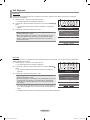
Adjusting the Volume
Using the Volume Button
1. Press the VOL – or VOL + button to increase or decrease the volume.
Using the MUTE button
At any time, you can cut off the sound using the MUTE button.
1. Press MUTE button and the sound cuts off.
“ ” is displayed on the screen.
2. To turn mute off, press the MUTE button again or simply press the
VOL – or VOL + button.
Viewing the Display
The display identies the current channel and the status of certain audio-video
settings.
1. Press the INFO button on the remote control.
The TV will display the channel, the type of sound, and the status of certain
picture and sound settings.
Press the INFO button once more or wait approximately 10 seconds and
the display disappears automatically.
➣
Viewing the Menus
1. With the power on, press the MENU button.
The main menu appears on the screen.
The menu’s left side has icons: Picture, Sound, Channel, Setup, Input,
Application.
2. Press the ▲ or ▼ button to select one of the icons.
Then press the ENTER button to access the icon’s sub-menu.
3. Press the EXIT button to exit.
The on-screen menus disappear from the screen after about one minute.
➣
Using the Button
The button is used to select stations that broadcast a digital signal.
1. For example, for Channel 7-1, press 7, then , then 1.
HD indicates the TV is receiving a Digital High Denition signal.
SD indicates the TV is receiving a Standard Denition signal.
For quick channel change, press the number buttons, then press the
ENTER button.
Using the PRE-CH Button to select the Previous Channel
1. Press the PRE-CH button. The TV will switch to the last channel viewed.
To quickly switch between two channels that are far apart, tune to one
channel, then use the number button to select the second channel.
Then use the PRE-CH button to quickly alternate between them.
➣
➣
➣
Mode
:
Standard
Backlight : 7
Contrast : 95
Brightness : 45
Sharpness : 50
Color : 50
Tint (G/R) : G50/R50
Detailed Settings
Picture
DTV Air
4-2
♥
TV #8
Dolby Digital
9:59 am - 10:59 am
Sun, Sep 3 1:45 pm
Life On Venus Avenue
No Detaild Information
1080i
|
16:9
|
English
BN68-01669A-00Eng.indb 14 2008-06-13 ¿ÀÈÄ 7:12:44

English - 15
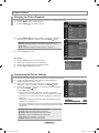
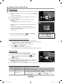
Using the TOOLS Button
You can use the TOOLS button to select your frequently used functions quickly and easily. The “Tools” menu changes
depending on which external input mode you are viewing.
1. Press the TOOLS button.
The “Tools” menu will appear.
2. Press the ▲ or ▼ button to select a menu.
3. Press the ▲/▼/◄/►/ENTER buttons to display, change, or use the
selected items. For a more detailed description of each function, refer to the
corresponding page.
Device List: see page 83
Picture Mode: see page 18
Sound Mode: see page 29
Sleep Timer: see page 48
Add to Favorite: see page 36
Switch to Cable (or Switch to Air): see page 15
PIP: see pages 27~28
Auto adjustment: see page 44
•
•
•
•
•
•
•
•
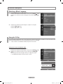
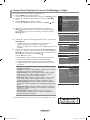
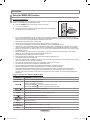
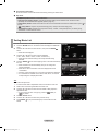
Memorizing the Channels
Your TV can memorize and store all of the available channels for both “off-air” (Air) and “Cable” channels. After the available
channels are memorized, use the CH or CH button to scan through the channels. This eliminates the need to change
channels by entering the channel digits. There are three steps for memorizing channels: selecting a broadcast source,
memorizing the channels (automatic) and adding or deleting channels (Channel Lists).
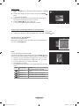
Selecting the Video Signal-source
Before your television can begin memorizing the available channels, you must
specify the type of signal source that is connected to the TV (i.e. an Air or a Cable
system).
1. Press the MENU button to display the menu.
Press the ▲ or ▼ button to select “Channel”, then press the ENTER
button.
2. Press the ENTER button to select “Antenna”.
Press the ▲ or ▼ button to select “Air” or “Cable”, then press the ENTER
button.
Press the EXIT button to exit.
Easy Setting
1. Press the TOOLS button on the remote control.
2. Press the ▲ or ▼ button to select “Switch to Cable (or Switch to Air)”.
3. Press the ENTER button to switch “Cable” (or “Air”).
Channel
Antenna
:
Air
Auto Program
Clear Scrambled Channel
Channel List
Fine Tune
Signal Strength
Channel
Antenna
:
Air ►
Auto Program
Clear Scrambled Channel
Channel List
Fine Tune
Signal Strength
Air
Cable
Tools
Device List
Picture Mode : Standard
Sound Mode : Custom
Sleep Timer : Off
Add to Favorite
Switch to Cable
e
Exit
Enter
Move
Tools
Device List
Picture Mode : Standard
Sound Mode : Custom
Sleep Timer : Off
Add to Favorite
Switch to Cable
e
Exit
Enter
Move
BN68-01669A-00Eng.indb 15 2008-06-13 ¿ÀÈÄ 7:12:44

English - 16
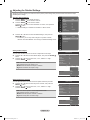
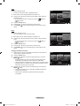
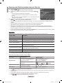
Storing Channels in Memory (Automatic Method)
1. Press the MENU button to display the menu.
Press the ▲ or ▼ button to select “Channel”, then press the ENTER
button.
2. Press the ▲ or ▼ button to select “Auto Program”, then press the ENTER
button.
3. Press the ▲ or ▼ button to select the antenna connection, then press the
ENTER button.
Air: “Air” antenna signal.
Cable: “Cable” antenna signal.
Auto: “Air” and “Cable” antenna signals.
4. When selecting the Cable TV system:
Press the ENTER button to start the auto program.
Press the ▲,▼, ◄ or ► to select the correct analog signal cable system
source among “STD”, “HRC”, and “IRC”. Press the ▲ or ▼ button to select
“Start”, then press the ENTER button. If you have Digital cable TV, select
the cable system signal source for both Analog and Digital.
STD, HRC and IRC identify various types of cable TV systems. Contact
your local cable company to identify the type of cable system that exists in
your particular area. At this point the signal source has been selected.
5. The TV begins memorizing all available stations.
After all the available channels are stored, it starts to remove scrambled
channels (see page 41). The Auto program menu then reappears.
If you want to stop Auto Programming, press the ENTER button.
The “Stop Auto Program?” message will be displayed. Select “Yes” by
pressing the ◄ or ► button, then press the ENTER button.
Press the
EXIT button to exit.
➣
➣
➣
➣
Channel
Antenna
:
Air
AutoProgram ►
Clear Scrambled Channel
Channel List
Fine Tune
Signal Strength
ReturnEnter
Auto Program
Select the Antenna source to memorize.
Air
Cable
Auto
Move
Start
Start
Start
Auto Program
Auto Program is completed.
3 channels are memorized.
DTV Cable : 1 Cable : 2
OK
ReturnEnter
Auto Program
Auto Program in Progress.
Stop
Enter
Cable 38
50%
Return
DTV Cable : 12 Cable : 32
Auto Program
Removing scrambled channel.
Stop
Enter
DTV Cable 41
77%
Return
DTV Cable : 16 Cable : 45
Auto Program
Stop Auto Program?
77%
ReturnEnter
No
Yes
Move
DTV Cable : 16 Cable : 45
Auto Program
Selects the cable system.
Analog
Digital
HRC IRC
HRC IRCSTD
Start
STD
ReturnEnter
Move
BN68-01669A-00Eng.indb 16 2008-06-13 ¿ÀÈÄ 7:12:45

English - 17
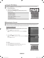
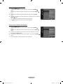
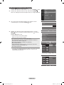
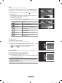
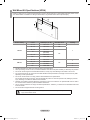
To Select the Source
Use to select TV or other external input sources such as DVD players or Cable
Box/Satellite receivers (Set-Top Box) connected to the TV. Use to select the input
source of your choice.
1. Press the MENU button to display the menu.
Press the ▲ or ▼ button to select “Input”, then press the ENTER button.
2. Press the ENTER button to select “Source List”.
Press the ▲ or ▼ button to select signal source, then press the ENTER
button.
Available signal sources: TV, AV1, AV2, S-Video, Component1,
Component2, PC, HDMI1, HDMI2/DVI, HDMI3, USB.
You can choose only those external devices that are connected to the TV.
In the “Source List”, connected inputs will be highlighted and sorted to the
top. Inputs that are not connected will be sorted to the bottom.
Using the Color buttons on the remote with the Source list
Red (Refresh): Refreshes the connecting external devices.
TOOLS (Option): Displays the “Edit Name” and “Information” menus.
•
•
Press the SOURCE button on the remote control to view an external signal
source.
➣
➣
➣
O
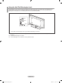
To Edit the Input Source Name
Name the device connected to the input jacks to make your input source selection easier.
1. Press the MENU button to display the menu.
Press the ▲ or ▼ button to select “Input”, then press the ENTER button.
Press the ▲ or ▼ button to select “Edit Name”, then press the ENTER
button.
2. Press the ▲ or ▼ button to select “AV1”, “AV2”, “S-Video”, “Component1”,
“Component2”, “PC”, “HDMI1”, “HDMI2/DVI”, “HDMI3” input jack, then press
the ENTER button.
3. Press the ▲ or ▼ button to select “VCR”, “DVD”, “Cable STB”,
“Satellite STB”, “PVR STB”, “AV Receiver”, “Game”, “Camcorder”, “PC”,
“TV”, “IPTV”, “Blu-Ray”, “HD DVD”, “DMA” input source, then press the
ENTER button.
Press the EXIT button to exit.
When a PC with a resolution of 1920 x 1080@60Hz is connected to the
HDMI IN 2 port, you should set the “HDMI2/DVI” mode to “PC” in the “Edit
Name” of the “Input” mode.
➣
Source List
Edit Name
Input
Source List
EditName ►
Input
Edit Name
AV1 : ---- ►
AV2 : ----
S-Video : ----
Component1 : ----
Component2 : ----
PC : ----
HDMI1 : ----
▼
Enter ReturnMove
TV
AV1 ----
AV2 ----
S-Video ----
Component1 ----
Component2 ----
Refresh
Option
Source List
Edit Name
AV1 : ----
AV2 : ----
S-Video : ----
Component1 : ----
Component2 : ----
PC : ----
HDMI1 : ----
Enter ReturnMove
----
VCR
DVD
Cable STB
Satellite STB
PVR STB
▼
BN68-01669A-00Eng.indb 17 2008-06-13 ¿ÀÈÄ 7:12:46

English - 18
Picture Control
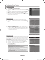
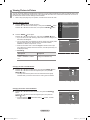
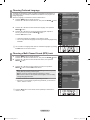
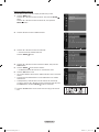
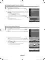
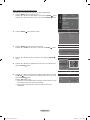
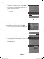
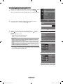
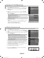
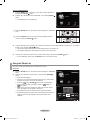
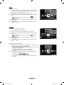
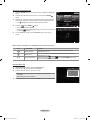
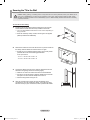
Changing the Picture Standard
You can select the type of picture which best corresponds to your viewing requirements.
1. Press the MENU button to display the menu.
Press the ENTER button to select “Picture”.
2. Press the ENTER button to select “Mode”. Press the ▲ or ▼ button to
select “Dynamic”, “Standard” or “Movie”. Press the ENTER button.
Dynamic: Selects the picture for high-denition in a bright room.
Standard: Selects the picture for the optimum display in a normal
environment.
Movie: Selects the picture for viewing movies in a dark room.
•
•
•
3. Press the EXIT button to exit.
Easy Setting
1. Press the TOOLS button on the remote control.
2. Press the ▲ or ▼ button to select “Picture Mode”.
3. Press the ◄ or ► button to select the required option.
4. Press the EXIT or TOOLS button to exit.
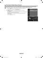
Customizing the Picture Settings
Your television has several setting options that allow you to control the picture quality.
1. To select the desired picture mode, follow the “Changing the Picture
Standard” instructions numbers 1 and 2.
2. Press the ▲ or ▼ button to select “Backlight”, “Contrast”, “Brightness”,
“Sharpness”, “Color” or “Tint(G/R)”, then press the ENTER button.
3. Press the ◄ or ► button to decrease or increase the value of a particular
item. Press the ENTER button.
Press the
EXIT button to exit.
When you make changes to “Backlight”, “Contrast”, “Brightness”,
“Sharpness”, “Color” or “Tint(G/R)”, the OSD will be adjusted accordingly.
In PC mode, you can only make changes to “Backlight”, “Contrast” and
“Brightness”.
Settings can be adjusted and stored for each external device you have
connected to an input of the TV.
The energy consumed during use can be signicantly reduced if the level
of brightness of the picture is reduced, and that this will reduce the overall
running cost.
Backlight: Adjusts the brightness of LCD back light.
Contrast: Adjusts the contrast level of the picture.
Brightness: Adjusts the brightness level of the picture.
Sharpness: Adjusts the edge denition of the picture.
Color: Adjusts color saturation of the picture.
Tint(G/R): Adjusts the color tint of the picture.
•
•
•
•
•
•
➣
➣
➣
➣
Picture
Mode
:
Dynamic
►
Backlight : 7
Contrast : 95
Brightness : 45
Sharpness : 50
Color : 50
Tint (G/R) : G50/R50
Detailed Settings
Dynamic
Standard
Movie
Mode : Standard
Backlight :7 ►
Contrast : 95
Brightness : 45
Sharpness : 50
Color : 50
Tint (G/R) : G50/R50
Detailed Settings
Picture Options
Picture
7Backlight
Enter ReturnAdjustMove
Mode
:
Standard
Backlight : 7
Contrast : 95
Brightness : 45
Sharpness : 50
Color : 50
Tint (G/R) : G50/R50
Detailed Settings
Picture
Tools
Device List
Picture Mode ◄ Standard ►
Sound Mode : Custom
Sleep Timer : Off
Add to Favorite
Switch to Cable
e
Exit
Adjust
Move
BN68-01669A-00Eng.indb 18 2008-06-13 ¿ÀÈÄ 7:12:46
La page charge ...
La page charge ...
La page charge ...
La page charge ...
La page charge ...
La page charge ...
La page charge ...
La page charge ...
La page charge ...
La page charge ...
La page charge ...
La page charge ...
La page charge ...
La page charge ...
La page charge ...
La page charge ...
La page charge ...
La page charge ...
La page charge ...
La page charge ...
La page charge ...
La page charge ...
La page charge ...
La page charge ...
La page charge ...
La page charge ...
La page charge ...
La page charge ...
La page charge ...
La page charge ...
La page charge ...
La page charge ...
La page charge ...
La page charge ...
La page charge ...
La page charge ...
La page charge ...
La page charge ...
La page charge ...
La page charge ...
La page charge ...
La page charge ...
La page charge ...
La page charge ...
La page charge ...
La page charge ...
La page charge ...
La page charge ...
La page charge ...
La page charge ...
La page charge ...
La page charge ...
La page charge ...
La page charge ...
La page charge ...
La page charge ...
La page charge ...
La page charge ...
La page charge ...
La page charge ...
La page charge ...
La page charge ...
La page charge ...
La page charge ...
La page charge ...
La page charge ...
La page charge ...
La page charge ...
La page charge ...
La page charge ...
La page charge ...
La page charge ...
La page charge ...
La page charge ...
La page charge ...
La page charge ...
La page charge ...
La page charge ...
La page charge ...
La page charge ...
La page charge ...
La page charge ...
La page charge ...
La page charge ...
La page charge ...
La page charge ...
La page charge ...
-
 1
1
-
 2
2
-
 3
3
-
 4
4
-
 5
5
-
 6
6
-
 7
7
-
 8
8
-
 9
9
-
 10
10
-
 11
11
-
 12
12
-
 13
13
-
 14
14
-
 15
15
-
 16
16
-
 17
17
-
 18
18
-
 19
19
-
 20
20
-
 21
21
-
 22
22
-
 23
23
-
 24
24
-
 25
25
-
 26
26
-
 27
27
-
 28
28
-
 29
29
-
 30
30
-
 31
31
-
 32
32
-
 33
33
-
 34
34
-
 35
35
-
 36
36
-
 37
37
-
 38
38
-
 39
39
-
 40
40
-
 41
41
-
 42
42
-
 43
43
-
 44
44
-
 45
45
-
 46
46
-
 47
47
-
 48
48
-
 49
49
-
 50
50
-
 51
51
-
 52
52
-
 53
53
-
 54
54
-
 55
55
-
 56
56
-
 57
57
-
 58
58
-
 59
59
-
 60
60
-
 61
61
-
 62
62
-
 63
63
-
 64
64
-
 65
65
-
 66
66
-
 67
67
-
 68
68
-
 69
69
-
 70
70
-
 71
71
-
 72
72
-
 73
73
-
 74
74
-
 75
75
-
 76
76
-
 77
77
-
 78
78
-
 79
79
-
 80
80
-
 81
81
-
 82
82
-
 83
83
-
 84
84
-
 85
85
-
 86
86
-
 87
87
-
 88
88
-
 89
89
-
 90
90
-
 91
91
-
 92
92
-
 93
93
-
 94
94
-
 95
95
-
 96
96
-
 97
97
-
 98
98
-
 99
99
-
 100
100
-
 101
101
-
 102
102
-
 103
103
-
 104
104
-
 105
105
-
 106
106
-
 107
107


Samsung LN40A630M1F Manuel utilisateur
- Catégorie
- Téléviseurs LCD
- Taper
- Manuel utilisateur
- Ce manuel convient également à
dans d''autres langues
- English: Samsung LN40A630M1F User manual
Documents connexes
-
Samsung LN-T4681F Manuel utilisateur
-
Samsung LN-T4042H Manuel utilisateur
-
Samsung LN40A550P3F Manuel utilisateur
-
-
-
-
-
-
-