Kozyheat Callaway See-Thru Le manuel du propriétaire
- Catégorie
- Cheminées
- Taper
- Le manuel du propriétaire

HUSSONG MANUFACTURING CO., INC.
READ ALL THESE STEPS
BEFORE STARTING INSTALLATION.
LEAVE THESE INSTRUCTIONS WITH THE
APPLIANCE.
This kit must be installed by a qualied installer,
service agency, or gas supplier at the time of
the heater installation. These instructions must
be used in conjunction with the installation and
operation manual provided with the appliance.
Please read the appliance owner’s manual
completely before performing any procedures in
these instructions.
INSTALLER: Leave this manual with the appliance.
CONSUMER: Retain this manual for future reference.
KOMFORT ZONE KIT
#KZK-054
For use with the #CLW-ST and #CLW-50 (Starting
Serial Number: 19 501780 50)
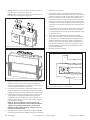
This optional convection duct kit redistributes the
warm air ow away from the replace opening to
a more desirable location using natural convection
without the use of a fan. The warm air ow may be
relocated to a position higher up the wall, out the
sidewalls, or even to an adjacent room. The result
is much cooler wall temperatures above the re-
place opening for locating televisions, artwork, etc.
English and French installation manuals are available through your
local dealer. Visit our website www.kozyheat.com.
Les manuels d’installation en français et en anglais sont disponibles
chez votre détaillant local. Visitez
www.kozyheat.com
.
Hussong Manufacturing Co., Inc.
P.O. Box 577, 204 Industrial Park Drive
Lakeeld, MN 56150-0577, USA
Rev. 4, 2/21
1.0 INTRODUCTION .......................................................................3
1.1 Kit Contents..........................................................................................3
1.2 Plenum Preparation .......................................................................... 4
1.3 Suggested Congurations .............................................................. 5
1.4 Dimensions ..........................................................................................7
1.5 Air Duct Run ......................................................................................... 8
2.0 FRAMING AND CLEARANCES ................................................9
2.1 Clearance to Sprinkler ...................................................................... 9
2.2 Framing................................................................................................10
2.3 #KZK-054 Clearances ......................................................................12
3.0 FACING AND FINISHING .......................................................14
3.1 Non-combustible Requirements ................................................ 14
3.2 Combustible Finish .......................................................................... 16
3.3 Hearth and Mantel Clearances ....................................................19
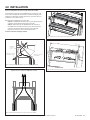
4.0 INSTALLATION .......................................................................21


Komfort Zone Kit #KZK-054 R.4 Hussong Mfg. Co., Inc. • Kozy Heat Fireplaces INTRODUCTION 3
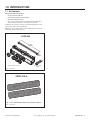
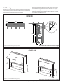
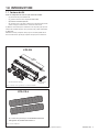
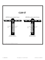
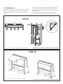
1.1 Kit Contents
ALL kit contents must be installed.
• (1) 54" plenum kit: KZK-054
• (1) plenum discharge trim: KZK-054DT
• (2) plenum support brackets
• (8) 6" collars - (4) to attach to the bottom of the plenum; (4) to
attach to the unit where the cover plates are removed
(1) KZK-410-6 is used for a 10' vent run. If installing beyond 10' vent
run, you will need to order (1) KZK-CPL6.
KZK-CPL6 is (6) 6" couplers that connect (2) KZK-410-6. You will only
need (4) 6" couplers for installation.
1.0 INTRODUCTION
56⁄”
(1425mm)
4
⁄”
(103mm)
(4) take o collars included
Plenum support
brackets
#K ZK-054
Figure 1.1, #KZK-054
Figure 1.2, #KZK-410-6
(4) - 10’ x 6” (aluminum ex) listed to UL-181Class 0 Air Duct
#KZK-410-6

4 INTRODUCTION Hussong Mfg. Co., Inc. • Kozy Heat Fireplaces Komfort Zone Kit #KZK-054 R.4
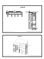
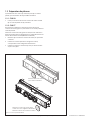
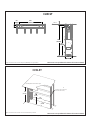
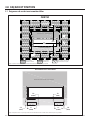
1.2 Plenum Preparation
The plenum included with this kit has (5) openings for (4) plenum
collars for installation for units #CLW-50 or #CLW-ST.
1.2.1 #CLW-50
1. The center cover plate does not need to be removed. Install (4)
plenum collars to (4) openings.
1.2.2 #CLW-ST
For certain installations, you may need to remove the center cover
plate (Figure 1.3) and install a plenum collar in the center of plenum.
Install the cover plate in the corresponding left or right side that you
need space for to maintain clearances to the vent system or heat
transfer kits (HTK-EXT or HTK-INT).
1. Remove the (4) screws securing the center cover plate, as show
below.
2. Install the plenum collar to either the right or left side,
depending on your installation.
3. Install cover plate to opening that is not used. Secure with (4)
screws.
Remove center cover plate
for certian installations.
Install 6” collar to left or right side,
depending on your installation.
Install cover plate over opening not used.
Figure 1.3, #KZK-054 Plenum Cover Plate

Komfort Zone Kit #KZK-054 R.4 Hussong Mfg. Co., Inc. • Kozy Heat Fireplaces INTRODUCTION 5
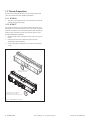
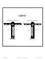
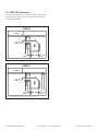
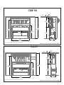
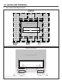
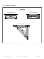
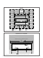
1.3 Suggested Congurations
Figure 1.4, #KZK-054 Suggested Congurations for CLW-50
#KZK-054 front wall outlet #KZK-054 rear wall outlet
#KZK-054 corner installation
CLW-50

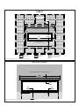
6 INTRODUCTION Hussong Mfg. Co., Inc. • Kozy Heat Fireplaces Komfort Zone Kit #KZK-054 R.4
Left side collar on
plenum installed
Right side collar on
plenum installed
Access/front
side
Fixed/back
side
Access/front
side
Fixed/back
side
CLW-ST
#KZK-054 front wall outlet #KZK-054 rear wall outlet
Figure 1.5, #KZK-054 Suggested Congurations for CLW-ST

Komfort Zone Kit #KZK-054 R.4 Hussong Mfg. Co., Inc. • Kozy Heat Fireplaces INTRODUCTION 7
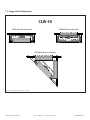
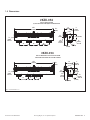
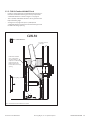
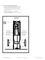
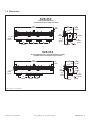
1.4 Dimensions
Figure 1.6, #KZK-054 Dimensions
54¼”
(1378mm)
14”
(355mm)
½”
(12mm)
stand-o
1
½”
(38mm)
stand-o
½”
(12mm)
stand-o
6”
(152mm)
4”
(102mm)
8
⁄” (220mm)
2
⁄”
(54mm)
2”
(50mm)
stand-o
12”
(304mm)
3
½”
(89mm)
14”
(355mm)
14”
(355mm)
#KZK-054
CLW-50 INSTALLATION
(4) COLLARS INSTALLED EQUAL DISTANCE APART
½”
(12mm)
stand-o
13”
(330mm)
8”
(203mm)
54
¼”
(1378mm)
3
½”
(89mm)
12”
(304mm)
2”
(50mm)
stand-o
2
⁄”
(54mm)
1
½”
(38mm)
stand-o
4”
(102mm)
6”
(152mm)
8⁄”
(220mm)
8”
(203mm)
1
½”
(38mm)
stand-o
#KZK-054
CLW-ST FRONT WALL OUTLET INSTALLATION
COLLAR INSTALLED ON LEFT SIDE OF PLENUM

8 INTRODUCTION Hussong Mfg. Co., Inc. • Kozy Heat Fireplaces Komfort Zone Kit #KZK-054 R.4
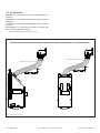
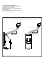
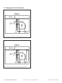
1.5 Air Duct Run
IMPORTANT: The air duct pipe cannot run horizontally without a
vertical rise.
IMPORTANT: The 1/2" clearance around the air duct pipes must be
maintained.
Use #KZK-410-6 UL181 Class 0 Air Duct piping to connect the plenum
to the unit.
Hussong Mfg. Co., Inc. requires pipes to be listed as UL181 Class 0 Air
Duct to connect the plenum(s) to the unit.
• CLW-50 & CLW-ST maximum vent run: 20' (6m)
Figure 1.7, Minimum Vent Pipe Run
WHEN INSTALLING AIR DUCT PIPE MAINTAIN A MINIMUM 4" VERTICAL RISE FOR EVERY 12" HORIZONTAL RUN
12”
(304mm)
4” (102mm)
12”
(304mm)
4” (102mm)
Minimum bend radius=5” (127mm)
Minimum bend radius=5” (127mm)
CLW-50 CLW-ST

Komfort Zone Kit #KZK-054 R.4 Hussong Mfg. Co., Inc. • Kozy Heat Fireplaces FRAMING AND CLEARANCES 9
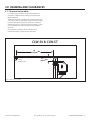
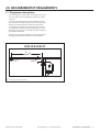
2.0 FRAMING AND CLEARANCES
Figure 2.1, KZK Clearance to Sprinkler
2.1 Clearance to Sprinkler
• In a situation where a sprinkler head is installed within the
proximity to a #KZK discharge opening, the diagram below
MUST be followed.
• The distance between a sprinkler head and discharge opening
cannot be less than 60" (1524mm) in length at every point from
the origin of the discharge opening. You must also verify the
sprinkler head sensor is set to the proper heat setting so it does
not activate when the room heats up from normal replace
operation.
• Please follow local building codes to determine what
temperature setting is relevant for your installation.
60”
(1524mm)
Min
3
½”
(89mm)
Min
Ceiling
Sprinkler Head
CLW-50 & CLW-ST

10 FRAMING AND CLEARANCES Hussong Mfg. Co., Inc. • Kozy Heat Fireplaces Komfort Zone Kit #KZK-054 R.4
5¾”
(146mm)
55
¼”
(1403mm)
74
½”
(1892mm)
68
¾”
(1746mm)
22”
(559mm)
Framing on Edge
Ceiling
Plenum
Framing
Plenum support
bracket
CLW-50
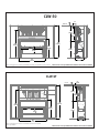
2.2 Framing
Shown in this section are rough opening dimensions for the plenum,
unit installation, and unit installation with a TV recess construction (if
applicable). See the following pages for clearances.
Rough opening framing dimensions should allow for wall covering
thickness and facing materials. Please refer to Section 3.0 on page
14 for specic facing and nishing options.
Attach the supplied plenum support brackets to the rear of plenum
and framing, as shown in Figure 2.2.
Figure 2.2, #KZK-054 Plenum Rough Opening for CLW-50
Figure 2.3, CLW-50 Unit Wall Enclosure Rough Opening
76”
(1930mm)
48”
(1219mm)
64
½”
(1638mm)
22”
(559mm)
44
½”
(1130mm)
4
¼”
(108mm)
76”
(1930mm)
64
½”
(1638mm)
22”
(559mm)
44
½”
(1130mm)
4
¼”
(108mm)
Steel Framing Required
Steel Framing Required
CLW-50
Dimensions reect minimum enclosure height
Dimensions reect minimum enclosure height

Komfort Zone Kit #KZK-054 R.4 Hussong Mfg. Co., Inc. • Kozy Heat Fireplaces FRAMING AND CLEARANCES 11
74½”
(1892mm)
68
¾”
(1746mm)
17”
(432mm)
5
¾”
(146mm)
55¼”
(1403mm)
Framing on Edge
Ceiling
CLW-ST
Figure 2.4, #KZK-054 Plenum Rough Opening for CLW-ST
Dimensions reect minimum enclosure height
76”
(1930mm)
43
¼”
(1098mm)
64
½”
(1638mm)
17”
(559mm)
Ceiling/Fireplace enclosure top
Single vertical
header
CLW-ST
Figure 2.5, CLW-ST Unit Wall Enclosure Rough Opening
Dimensions reect minimum enclosure height

12 FRAMING AND CLEARANCES Hussong Mfg. Co., Inc. • Kozy Heat Fireplaces Komfort Zone Kit #KZK-054 R.4
½”
(13mm)
Min
3
½”
(89mm)
Min
½”
(13mm)
Min
Ceiling
CLW-50
Figure 2.6, CLW-50 Minimum Clearance from Air Discharge to Ceiling
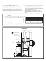
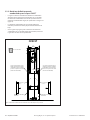
2.3 #KZK-054 Clearances
Shown below are minimum clearances for the air discharge opening.
See the following page for clearances for #KZK-054 installation for
units CLW-50 and CLW-ST.
Figure 2.7, CLW-ST Minimum Clearance from Air Discharge to Ceiling
½”
(13mm)
Min
3
½”
(89mm)
Min
½”
(13mm)
Min
Ceiling
CLW-ST

Komfort Zone Kit #KZK-054 R.4 Hussong Mfg. Co., Inc. • Kozy Heat Fireplaces FRAMING AND CLEARANCES 13
39”
(991mm)
17”
(432mm)
31”
(787mm)
37”
(940mm)
3
½”
(89mm)
65
¼”
(1657mm)
64
½”
(1638mm)
16
¾”
(425mm)
53
½”
(1359mm)
43
¼”
(1098mm)
76”
(1930mm)
Ceiling
CLW-ST
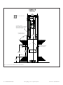
Figure 2.9, #KZK-054 and CLW-ST Framed Opening and Clearances
Dimensions reect minimum enclosure height
65¼”
(1657mm)
64
½”
(1638mm)
53
½”
(1359mm)
44
½”
(1131mm)
76”
(1930mm)
37”
(940mm)
3
½”
(89mm)
31”
(787mm)
39”
(993mm)
22”
(559mm)
16
¾”
(425mm)
Ceiling
Steel Framing Required
CLW-50
Figure 2.8, #KZK-054 and CLW-50 Framed Opening and Clearances
Dimensions reect minimum enclosure height

14 FACING AND FINISHING Hussong Mfg. Co., Inc. • Kozy Heat Fireplaces Komfort Zone Kit #KZK-054 R.4
3.0 FACING AND FINISHING
3.1 Non-combustible Requirements
21½”
(545mm)
66”
(1676mm)
6
⁄”
(161mm)
48
¾”
(1238mm)
53
½”
(1359mm)
16
¾”
(425mm)
10
½”
(267mm)
Combustible Finishing
Material Allowed
Non-Combustible Finishing Material Only
Steel Framing Required
Lower Cover Panel
Combustible Finishing Material Allowed
CLW-50
Non-combustible
nishing material only
Combustible nishing
material allowed
Combustible nishing material
allowed. See image below for
acceptable screw locations.
3¾”
(95mm)
13”
(330mm)
9
¾”
(248mm)
1
½”
(38mm)
13”
(330mm)
3
¾”
(95mm)
No Screws Allowed
No Screws Allowed
No Screws Allowed
Non-Combustible Finishing Material Only
SCREW PATTERN LOCATIONS
Figure 3.1, CLW-50 Minimum Non-combustible Finishing Dimensions
Figure 3.2, CLW-50 Minimum Non-combustible Finishing Dimensions Screw Locations

Komfort Zone Kit #KZK-054 R.4 Hussong Mfg. Co., Inc. • Kozy Heat Fireplaces FACING AND FINISHING 15
7”
(178mm)
16
¾”
(425mm)
67
½”
(1714mm)
18”
(457mm)
53
½”
(1359mm)
45
¼”
(1149mm)
10
½”
(267mm)
Combustible nishing
material allowed
Non-combustible nishing material only
Lower cover panel
Combustible nishing material allowed
Non-combustible
nishing material only
Combustible nishing
material allowed
Combustible nishing material
allowed. See image below for
acceptable screw locations.
CLW-ST
59½”
(1512mm)
2
½”
(64mm)
1
½”
(38mm)
9
¾”
(248mm)
Non-combustible nishing material only
No Screws Allowed
No Screws Allowed
Screw Pattern Locations
Figure 3.3, CLW-ST Minimum Non-combustible Finishing Dimensions
Figure 3.4, CLW-ST Minimum Non-combustible Finishing Dimensions Screw Locations

16 FACING AND FINISHING Hussong Mfg. Co., Inc. • Kozy Heat Fireplaces Komfort Zone Kit #KZK-054 R.4
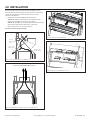
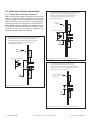
3.2 Combustible Finish
3.2.1 Trim Installation
NOTE: It is not required to use the #KZK-054 discharge trim (#KZK-
054DT) if desired to run nishing material up to the nishing material
stando. Finishing material must not block the opening and must be
run evenly along the plenum opening.
WARNING! RISK OF OVERHEATING AND FIRE! Ensure the KZK duct
system is installed in accordance to this manual AND the convection
bae is removed when using these combustible clearances.
Figure 3.5, Drywall Finish
Figure 3.6, Combustible Finish Material up to 1" Thick
Figure 3.7, Non-combustible Material Trim Finish
Combustible
Material
Discharge Trim
Drywall stops at nishing material standos around KZK
discharge opening. The discharge trim covers these
edges completely.
3¾”
(95mm)
43⁄8”
(111mm)
Discharge Trim
Combustible
Material up to
1” (25mm) thick
Up to 1” (25mm) thick combustible material up to the edge
of discharge trim. 1” (25mm) combustible material cannot go
closer to discharge opening.
1” (25mm) combustible material goes on top of any
required non-combustible material on the replace.
2¼”
(57mm)
Non-combustible
material up to
discharge opening
Non-combustible materials, such as tile or stone, up to the air discharge
opening. Minimum air discharge opening must be maintained the entire
length of the air discharge opening.
Discharge trim is optional for this installation.

Komfort Zone Kit #KZK-054 R.4 Hussong Mfg. Co., Inc. • Kozy Heat Fireplaces FACING AND FINISHING 17
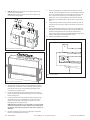
3.2.2 CLW-50 Combustible Wall Finish
• Figure 3.8 shows installation of combustible wall nish up to 1"
thick. This combustible material goes over any required non-
combustible materials as shown in Figure 3.1 on page 14.
• This 1" (25mm) combustible material is able to go down to the
replace nishing edge.
• See Figure 3.6 on page 16 for up to 1" (25mm) thick
combustible material installation around the discharge trim of
the KZK air discharge opening.
Figure 3.8, #KZK-054 Combustible Wall Finish for CLW-50
½
” (13mm) clearance
around pipe
Combustible wall nish
up to 1” (25mm) thick
may be installed over
required non-combustible
material up to the top
nishing edge and the
bottom of the air discharge
opening
Finishing Edge
Fireplace Enclosure Floor
Non-combustible zone
Steel
Framing
CLW-50

18 FACING AND FINISHING Hussong Mfg. Co., Inc. • Kozy Heat Fireplaces Komfort Zone Kit #KZK-054 R.4
3.2.3 CLW-ST Combustible Wall Finish
• Figure 3.9 shows installation of combustible wall nish up to 1"
thick. This combustible material goes over any required non-
combustible materials as shown in Figure 3.3 on page 15.
• This 1" (25mm) combustible material is able to go down to the
replace nishing edge.
• See Figure 3.6 on page 16 for up to 1" (25mm) thick
combustible material installation around the discharge trim of
the KZK air discharge opening.
Combustible wall nish
up to 1” (25mm) thick
may be installed over
required non-combustible
material up to the top
nishing edge and the
bottom of the air
discharge opening
Finishing
edge
Combustible wall nish
up to 1” (25mm) thick
may be installed over
required non-combustible
material up to the top
nishing edge and the
bottom of the air
discharge opening
Finishing
edge
Fireplace enclosure oor
Non-combustible
material only
Non-combustible
material only
76”
(1930mm)
17”
(432mm)
Non-combustible zone
CLW-ST
Figure 3.9, #KZK-054 Combustible Wall Finish for CLW-ST

Komfort Zone Kit #KZK-054 R.4 Hussong Mfg. Co., Inc. • Kozy Heat Fireplaces FACING AND FINISHING 19
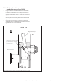
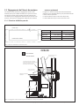
3.3 Hearth and Mantel Clearances
The following drawings show the hearth and mantel clearances
allowed for the CLW-50 and CLW-ST with no surround or optional
surrounds installed. The CLW-50 and CLW-ST use the same optional
surrounds. Follow the drawings for the minimum distance needed
between the hearth and mantel when installing an optional surround
to allow for proper servicing clearances.
3.3.1 Finishing Guidelines for Optional Surrounds
• Figure 3.10 shows where to end nishing materials, when
measuring from the nishing edge, to allow installation of any
optional surround. Most nishing material will not t behind the
optional surround(s) when it is installed.
• Measurement 'A' shows the space to leave on each side.
• Measurement 'B' shows the space to leave on the top and the
bottom.
Figure 3.10, Finishing Guidelines for Optional Surrounds for CLW-50 & CLW-ST
Steel
Framing
Non-Combustible Zone
16¾”
(425mm)
26
½”
(673mm)
9
¾”
(248mm)
12” (305mm)
9” (229mm)
6” (152mm)
12” (305mm)
9” (229mm)
6” (152mm)
Combustible wall nish
may be installed over non-combustible
material and butt up to the nshing
edge around the opening
Each square represents
1” (25mm) of projection
Finishing Edge
Fireplace Enclosure Floor
Finishing Edge
½” (13mm) clearance
around pipe
Non-combustible
material
CLW-50
No surround
Figure 3.11, CLW-50 Hearth and Mantel Clearances for No Surround
Surround A B
CW50-RS 3/4" (19mm) 3/4" (19mm)
CW50-RS4 2-5/8" (66mm) 2-5/8" (66mm)
CW50-GS 6" (152mm) 2-1/2" (64mm)
CW50-FS 3-1/8" (79mm) 3-1/8" (79mm)
B
A
Finishing Trim Edge
Surround Edge

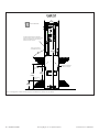
20 FACING AND FINISHING Hussong Mfg. Co., Inc. • Kozy Heat Fireplaces Komfort Zone Kit #KZK-054 R.4
17”
(432mm)
76”
(1930mm)
19
¾”
(502mm)
29
½”
(750mm)
9
¾”
(248mm)
3”
(76mm)
6” (152mm)
9” (229mm)
12” (305mm)
6” (152mm)
9” (229mm)
12” (305mm)
Each square represents
1” (25mm) of projection
Combustible wall nish
may be installed over non-combustible
material and butt up to the nishing
edge around the opening
Top nishing edge
Bottom
nishing edge
Non-combustible material
(both sides of replace)
Fireplace Enclosure Floor
Non-combustible zone
CLW-ST
No surround
Figure 3.12, CLW-ST Hearth and Mantel Clearances for No Surround
La page est en cours de chargement...
La page est en cours de chargement...
La page est en cours de chargement...
La page est en cours de chargement...
La page est en cours de chargement...
La page est en cours de chargement...
La page est en cours de chargement...
La page est en cours de chargement...
La page est en cours de chargement...
La page est en cours de chargement...
La page est en cours de chargement...
La page est en cours de chargement...
La page est en cours de chargement...
La page est en cours de chargement...
La page est en cours de chargement...
La page est en cours de chargement...
La page est en cours de chargement...
La page est en cours de chargement...
La page est en cours de chargement...
La page est en cours de chargement...
La page est en cours de chargement...
La page est en cours de chargement...
La page est en cours de chargement...
La page est en cours de chargement...
-
 1
1
-
 2
2
-
 3
3
-
 4
4
-
 5
5
-
 6
6
-
 7
7
-
 8
8
-
 9
9
-
 10
10
-
 11
11
-
 12
12
-
 13
13
-
 14
14
-
 15
15
-
 16
16
-
 17
17
-
 18
18
-
 19
19
-
 20
20
-
 21
21
-
 22
22
-
 23
23
-
 24
24
-
 25
25
-
 26
26
-
 27
27
-
 28
28
-
 29
29
-
 30
30
-
 31
31
-
 32
32
-
 33
33
-
 34
34
-
 35
35
-
 36
36
-
 37
37
-
 38
38
-
 39
39
-
 40
40
-
 41
41
-
 42
42
-
 43
43
-
 44
44


Kozyheat Callaway See-Thru Le manuel du propriétaire
- Catégorie
- Cheminées
- Taper
- Le manuel du propriétaire
dans d''autres langues
Documents connexes
-
Kozyheat Callaway 50 Le manuel du propriétaire
-
kozy heat Bellingham 44 Le manuel du propriétaire
-
-
-
-
-
-
-
-