MULTIPLEX Picocontrol 400 Bec Le manuel du propriétaire
- Catégorie
- Jouets télécommandés
- Taper
- Le manuel du propriétaire
Ce manuel convient également à

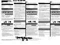
Blick auf die Steckkontakte am Motoranschluss
Pin layout of motor connector, looking at the plug contacts
Vue sur les fiches de branchement Moteur
Hinweise zur ersten Inbetriebnahme
1. Stellen Sie sicher, daß kein Empfängerakku am
Empfänger angeschlossen ist.
Bringen Sie das Bedienelement für die Motor-
steuerung in die Leerlaufstellung (Motor AUS) und
schalten Sie den Sender ein.
Schließen Sie das Servokabel des Reglers
an
den vorgesehenen Kanal des Empfängers
an
und verbinden Sie Regler
und Antriebsakku
.
Wenn Sie jetzt Vollgas geben, muß am Regler
die LED (grün) aufleuchten.
Trennen Sie den Antriebsakku vom Regler!
2. Verbinden Sie den Motor
(möglichst ohne Luft-
schraube) mit dem Regler
und befestigen Sie
Motor/Modell sicher.
Wenn die Luftschraube bereits montiert ist, prüfen
Sie, ob ausreichend Platz zum Ausklappen/Dre-
hen vorhanden ist. Entfernen Sie Gegenstände,
die angesaugt oder weggeblasen werden können
(Kleidungsstücke, Kleinteile, Papier, usw.) aus der
Nähe der Luftschraube.
3. Bringen Sie das Bedienelement für die Motor-
steuerung in die Leerlaufstellung (Motor AUS) und
schalten Sie den Sender ein.
Schließen Sie den Antriebsakku
wieder an und
prüfen Sie die Drehrichtung des Motors. Falls er-
forderlich Motor umpolen.
Beim Umpolen Akku abtrennen!
Tipp:
Anstelle des Motors können Sie zum Prüfen
des Reglers auch eine Glühlampe (z.B. 12V/21W
Bremslicht PKW) nehmen.
Sicherheitshinweise
Falsch gepolte Akkuanschlußkabel
zerstören den Regler!
Rotes Kabel an den PLUS-Pol,
schwarzes Kabel an den MINUS-Pol.
Wärmestau vermeiden!
Packen Sie den Regler nicht in Schaumgummi ein
und meiden Sie die Nähe anderer Wärmequellen
(Akku, Motor).
Tipp:
Bauen Sie den Regler so in das Modell ein,
dass die LED zur Kontrolle sichtbar bleibt.
Einschaltschutz
Der Einschaltschutz verhindert, dass der Antrieb bei
Einschalten der Empfangsanlage ungewollt los läuft.
Erst nachdem der Geber länger als 2 sec. in Leerlauf-
stellung war, wird der Regler aktiviert und reagiert beim
nächsten Gasgeben.
Einschalten der Anlage:
1. Geber für die Motorsteuerung in Leerlaufstellung
(Motor AUS) bringen, damit der Motor nicht unge-
wollt losläuft.
2. Sender einschalten.
3. Antriebsakku an den Regler anschließen.
Ausschalten der Anlage:
1. Antriebsakku vom Regler trennen
2. Sender ausschalten.
Regler für Elektroflug
Technische Daten
Dauerstrom 30 A
Spitzenstrom 40 A (max. 2 min)
Anzahl NC-Zellen 6 - 12
BEC 5 V / 1,5 A
Taktfrequenz 1 kHz
Abmessungen ca. 28 x 40 x 10 mm
Gewicht ca. 49 g
Besondere Eigenschaften
• Einschaltschutz (siehe rechts)
• LED zur Vollgasanzeige
• MULTIPLEX-Hochstromanschluß
BEC = Battery Eliminating Circuit, Empfänger-
stromversorgung aus dem Antriebsakku
BEC heißt: Der Empfänger und die Servos werden
aus dem Antriebsakku mit Strom versorgt. Im Modell
dürfen Sie daher keinen zusätzlichen Empfängerakku
anschließen.
Beachten Sie jedoch, daß die BEC-Versorgung nur
kurzzeitig 1,5 A für die Empfangsanlage im Modell ab-
geben kann. Für die Praxis bedeutet das:
Antriebsakku maximal anschließbar sind
6 - 10 Zellen 3 Standard-Servos
11 - 12 Zellen 2 Standard-Servos
Wenn in Ihrem Modell mehr Servos vorhanden sind,
müssen Sie die BEC-Versorgung unterbrechen und
zusätzlich einen Akku für den Empfänger einbauen.
Am Empfängeranschlußkabel des Reglers muß dazu
der rote Draht unterbrochen werden.
Wichtig (nicht nur) bei BEC-Betrieb!
Wenn Sie hören, daß die Drehzahl deutlich
abnimmt:
Sofort landen!
Die sinkende Drehzahl ist ein Anzeichen dafür, daß
der Akku leer wird. Wenn Sie jetzt das Gas zurückneh-
men und den Landeanflug einleiten, reicht die verblei-
bende Akkuladung in den meisten Fällen sogar noch
für einen zweiten Versuch, wenn der erste Anflug nicht
„paßt“.
Tipp für Notlandungen:
Ruhig bleiben!
Ein „fast“ leerer Akku ist kein Grund in Panik zu gera-
ten, wenn Sie:
• Sofort den Antrieb ausschalten!
Der Akku muß dann nur noch die Empfangsan-
lage mit Strom versorgen und kann sich etwas „er-
holen“. Im Endanflug können Sie dann noch ein-
mal für einige Sekunden „Gas geben“, wenn es
nötig werden sollte.
• Sofort den Landeanflug einleiten!
Bleiben Sie möglichst lange im Gleitflug um dem
Akku mehr Zeit zum Erholen zu lassen.
• Nicht versuchen um jeden Preis den Landeplatz zu
erreichen! Eine kontrollierte Außenlandung ist
weniger riskant, als das Modell „mit letzter Kraft
auf den Platz zu quälen“.
Control 400 DUO BECControl 400 DUO BEC
Control 400 DUO BECControl 400 DUO BEC
Control 400 DUO BEC
#82 5622
Tips for the first time use
1. Ensure that there is no separate receiver battery
connected to your receiver.
Move the throttle control to the idle position (motor
OFF) and switch the transmitter on.
Connect the servo lead attached to the speed
controller
to the receiver
throttle channel socket
and connect the flight pack
to the speed con-
troller
.
If you now apply full throttle at the transmitter, the
LED (green) on the speed controller
should light
up.
Disconnect the flight battery again!
2. Connect the motor
(without prop. fitted) to the
speed controller
and secure the motor/model
carefully.
If the motor is already fitted with a propeller, check
that there is plenty of space for the propeller to
unfold and spin. Remove from the vicinity of the
propeller any objects which could be sucked into
the airflow or blown away by it (items of clothing,
small parts, paper etc.).
3. Move the transmitter throttle control to the idle
position (or OFF) and switch the transmitter on.
Connect the flight battery
again and check the
direction of rotation of the motor. If it turns in the
wrong direction you will have to swap over the wires
at the motor terminals.
If you have to reverse the polarity:
Disconnect the battery while soldering!
Tip:
You can use a filament bulb (e.g. 12 V/21 W
car brake light bulb) instead of a motor for the test.
Safety notes
Battery leads with reversed polarity
will immediately ruin the controller!
Red wire to the POSITIVE (+) terminal,
black wire to the NEGATIVE (-) terminal.
Avoid any heat build-up!
Do not wrap the speed controller in foam plastic,
and keep it away from other heat sources (battery,
motor).
Wherever possible, install the speed controller in
the model in a position where you can see and
check the LED.
Power-on protection
The power-on protection circuit will prevent the motor
bursting into life when you switch the system on. The
controller will not work at all until you hold the throttle
stick at idle for at least 2 sec.
Switching on sequence:
1. Move the transmitter throttle control to the idle
position (motor OFF), so that the motor will not try
to start up and run.
2. Switch on the transmitter.
3. Connect the flight battery to the speed controller.
Switching off sequence:
1. Disconnect the flight battery
from the speed controller.
2. Switch off the transmitter.
Variateur pour Vol électr.
Caractéristiques techniques
Intensité en continu 30 A
Intensité maxi 40 A (< 2 min.)
Nombre d’éléments 6 - 12
BEC 5 V / 1,5 A
Fréquence 1 kHz
Dimensions env. 28 x 40 x 10 mm
Poids env. 49 g
Caractéristiques particulières
• Protection de mise en route
• LED pour indication plein gaz
• Prise MULTIPLEX haute intensité
BEC = Battery Eliminating Circuit, Aliment.
du récepteur à partir de l’accu de prop.
BEC signifie: les servos et le récepteur sont alimentés
à partir de l’accu de propulsion. De ce fait, il ne doit y
avoir aucun autre accu complémentaire de réception
dans votre modèle.
Cependant n’oubliez pas que l’alimentation BEC peut
donner 1,5 A (seulement un peu de temps) à votre
ensemble de réception. En pratique cela signifie:
L’accu de prop. brancher au maximum:
6 à 10 élém. 3 servos standards
11 à 12 élém. 2 servos standards
S’il y a plus de servos dans votre modèle, il faut couper
l’alimentation BEC et rajouter un accu de réception
complémentaire. Au niveau du cordon de
raccordement du récepteur, il faudra dans ce cas
couper le fil rouge.
Important en fonctionnement BEC !
Si vous entendez que la vitesse de rotation
diminue:
Atterrissez immediatement!
Un nombre de tours qui diminue est le signe que l’accu
se vide. Si vous coupez les gaz maintenant et si vous
faites votre approche finale, le courant qui reste dans
l’accu suffit pour poser le modèle sans problèmes, et
même pour un second tour de piste si votre première
approche était trop courte.
Même si la situation devient critique:
Gardez votre calme!
Un accu presque vide ne doit pas vous paniquer si:
• vous coupez immédiatement le moteur!
Dans ce cas, l’accu n’a plus qu’à alimenter la ré-
ception, et peut de ce fait se «rétablir». Pendant la
phase finale d’approche, vous pourrez ainsi
remettre le moteur en marche pour quelques
secondes si cela était nécessaire.
• vous entamez immédiatement votre approche finale
pour l’atterrissage!
Restez le plus longtemps possible en plané, pour
économiser au maximum la capacité de l’accu.
• vous n’essayez pas à tout prix de rejoindre la piste!
Un atterrissage contrôlé à l’extérieur de la piste
est beaucoup moins risqué qu’ attérrissage
«forcé» sur la piste.
El. flight speed controller
Specification
Continous current 30 A
Peak current 40 A (max. 2 min)
No. of NC cells 6 - 12
BEC 5 V / 1,5 A
Pulse frequency 1 kHz
Dimensions approx. 28 x 40 x 10 mm
Weight approx. 49 g
Special features
• Power-on protection (see right hand side)
• LED full throttle indicator
• MULTIPLEX high-current connector
BEC = Battery Eliminating Circuit, Receiver
power supply from the flight battery
BEC means: the flight battery supplies power to the
receiver and servos as well as to the motor. This means
that you do not need a separate receiver battery in
the model.
Please note however that the BEC circuit can supply
1.5 A for a short time only to the model’s receiving
system. In practice this means:
Flight batt. type Maximum no. of servos
6 - 10 cells 3 Standard Servos
11 - 12 cells 2 Standard Servos
If your model is fitted with more servos than this, then
you will have to switch the BEC system out of circuit
and install a separate receiver battery. The BEC
system is disabled by cutting through the red wire in
the receiver lead attached to the speed controller.
Important - and not only with the BEC system!
You will hear clearly when motor speed
starts to fall off:
Land immediately!
The reduction in rotational speed is your signal that
the battery is almost at the end of its capacity. If you
now reduce throttle and start the landing approach,
the residual battery charge is usually ample for a safe
landing, and even a second attempt if the first approach
is not quite right.
Tip for an emergency landing:
Stay cool!
An almost discharged battery calls for prompt action,
but it is no reason to panic. All you have to do is this:
• Switch off the motor without delay!
In this situation the battery only has to power the
receiving system, and will recover slightly. On the
final approach you will now find that you can apply
motor power for a few seconds if you need to.
• Start the landing approach immediately!
Keep the model gliding for as long as you can to
give the battery more time to recover.
• Don’t stretch the approach in an attempt to reach
the landing site at all costs! A controlled landing
some distance away is less risky than dragging
the model back to the patch with the last ounce of
power.
PiCO Control 400 DUO BEC # 82 5623 (00-03-30) 1/2
MULTIPLEX
Modelltechnik GmbH, Neuer Weg 15, D-75223 Niefern
MPX # 7 5023 UNI # 7 5024

F:
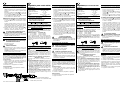
Vue sur les fiches de branchement Moteur
E:
Vistazo a los contactos en la conexión del motor
I:
Contatti della spina motore
Regolatore
per aeromodelli elettr.
Dati tecnici
Corrente 30 A
Corrente max. 40 A (< 2 min.)
Numero elementi 6 - 12
BEC 5 V / 1,5 A
Frequenza di lavoro 1 kHz
Dimensioni ca. 28 x 40 x 10 mm
Peso ca. 49 g
Caratteristiche particolari
• Protezione avviamento
LED per motore al massimo
• Connettori alta tensione MULTIPLEX
BEC = Battery Eliminating Circuit, Alimenta-
zione della ricevente dal pacco batterie
BEC significa: La ricevente ed i servi vengono alimentati
dal pacco batterie.
Non collegare un’ulteriore batteria
alla ricevente. Se si usa BEC anche l’interruttore Rx è
superfluo.
Importante: BEC può alimentare l’impianto RC 1,5 A
per tempo corto. In pratica questo significa:
Pacco batterie si possono collegare max.
6 - 10 elem. 3 servi standard
11 - 12 elem. 2 servi standard
Se nel Suo modello ci sono più servi è necessario
interrompere l’alimentazione BEC e montare un’ul-
teriore batteria per l’impianto RC. Il filo rosso del cavo
che collega il regolatore alla ricevente deve essere
interrotto.
Importante (non solo) per funzionamentoBEC!
Se si sente che il numero di giri diminuisce:
Atterrare immediatamente!
La diminuzione del numero di giri indica che la batteria
sta per scaricarsi. Se adesso si toglie motore e si
prepara l’avvicinamento la carica rimanente della
batterie permette, nella maggior parte dei casi, anche
un secondo avvicinamento, nel caso in cui il primo
non fosse “riuscito”.
Anche in atterraggi d’emergenza:
Mantenere la calma!
Una batteria “quasi” scarica non è un motivo per farsi
prendere dal panico:
• se Lei disinserisce immediatamente il motore!
La batteria, dovendo solo più alimentare l’impianto
RC, può “rigenerarsi”. In atterraggio sarà così
possibile dare motore per qualche secondo, se
dovesse essere necessario.
• se Lei prepara immediatamente l’atterraggio!
Cerchi di rimanere il più a lungo possibile in volo
planato per permettere alla batteria di “rigenerarsi”.
• se Lei non cerca di raggiungere ad ogni costo il
campo di volo!
Un atterraggio controllato fuori campo è spesso
meno rischioso del voler raggiungere a tutti i costi
il campo di volo.
Regulador para vuelo eléctr.
Datos técnicos
Corriente constante 30 A
Corriente máxima 40 A (máx. 2 min.)
Cantidad de células NC 6 - 12
BEC 5 V / 1,5 A
Frequencia de contacto 1 kHz
Medidas unos 28 x 40 x 10 mm
Peso unos 49 g
Características especiales
• Protección de calentamiento
• LED para la indicación de todo gas
• Connex. de alta corr. MULTIPLEX
BEC = Battery Eliminating Circuit, Aliment. de
corriente de la batería de arranque
BEC significa: el receptor y los servos se alimentan
con corriente de la batería de arranque. Por eso, en el
modelo no puede conectar en ningún caso una
batería adicional para el receptor.
Sin embargo, fíjese que la alimentación BEC tenga
1,5 A per tiempo corte para la instalación del receptor.
En la práctica, eso significa:
Batería de aranque. conectable máx.
6 a 10 células 3 servos estandar
11 a 12 células 2 servos estandar
Si en su modelo hay más servos, tendrá que inter-
rumpir la alimentación BEC e instalar una batería del
receptor adicional. Para ello tendrá que interrumpir
en el cable de conexión del receptor del regulador el
alambre rojo.
¡Importante (no solo) en el funcionam. BEC!
Usted escucha que la cantidad de revoluciones
disminuye:
¡Aterrizar inmediatamente!
La cantidad de revoluciones en disminución es una
señal de que la batería se está descargando. Si ahora
quita motor y se dispone a aterrizar, la carga de la
batería restante bastará, en la mayoría de los casos
para un segundo intento, si la primera “toma” no ha
salido bien.
También en caso de aterrizajes de emergencia:
¡Mantener la calma!
Una batería “casi” vacía no es motivo para entrar en
pánico, si:
• ¡apaga inmediatamente en arranque! La batería solo
tendrá que abastecer el equipo del receptor con
corriente y se podrá “recuperar” un poco. en la
aproximación podrá darle un poco más de gas
durante unos segundos más, si fuera necesario.
• ¡comenzar inmediatamente con la labro del
aterrizaje! Manténgase el máximo tiempo posible
en vuelo de planeo para darle más tiempo a la
batería a recuperarse.
• ¡no intente a toda costa llegar al campo de vuelo!
Un aterrizaje fuera de campo controlado es menos
arriesgado que “forzar al modelo a llegar como
sea al campo”.
La première mise en service
1. Assurez-vous qu’aucun accu de réception est
branché sur votre récepteur.
Mettez votre élément de commande du moteur en
position neutre (arrêt moteur) et allumez votre
émetteur.
Branchez le cordon du variateur
sur la voie qui
lui est réservée sur le récepteur
et branchez
l’accu de propulsion
au variateur
.
Si sur l’émetteur vous êtes déjà plein gaz, la LED
sur le variateur doit s’allumer (verte).
Débranchez de nouveau l’accu de propulsion!
2. Branchez le moteur
(si possible sans l’hélice)
au variateur
et fixez correctement moteur/
modèle.
Si l’hélice est déjà montée, assurez-vous qu’il y a
suffisamment de place autour . Eloignez tout ce
qui pourrait être aspiré ou soufflé (pièce d’habil-
lement, petites pièces diverses, papiers etc.)
3. Branchez de nouveau l’accu de propulsion
et
vérifiez le sens de rotation du moteur. Si
nécessaire, inversez la polarité du moteur.
Lors de la soudure, débranchez l’accu,
si vous devez inverser la polarité!
Conseil:
Pour les essais, à la place du moteur,
vous pouvez également utiliser une lampe (par
exemple 12V/21W, frein de voiture).
Conseils de sécurité
Une inversion de la polarité du cordon
de branchement de l’accu endommage
immédiatement le variateur!
Fil rouge sur le PLUS,
fil noir sur le MOINS.
Evitez la surchauffe !
N’enveloppez pas votre variateur dans de la
mousse, et évitez d’autres sources de chaleur à
proximité (accu/moteur).
Conseil:
Montez votre variateur dans le modèle avec
la LED restante visible, pour contrôle.
Protection de mise en route
Cette sécurité de mise en route évite, lorsque l’on
allume l’émetteur, un démarrage inopiné du moteur.
Le variateur n’est activé que si l’élément de commande
des gaz est en position Arrêt pendant plus de 2 sec.
et ne réagit qu’a la plrochaine remise des gaz.
La mise en route:
1. Mettre le manche de commande du moteur en
position neutre (Arrêt moteur) pour éviter que le
moteur ne se mettre en route inopinément.
2. Allumez l’émetteur.
3. Branchez l’accu de propulsion au variateur.
Coupez l’ensemble:
1. Débranchez l’accu de propulsion du variateur.
2. Coupez l’émetteur.
Consejos para el primer uso
1. Asegure que no haya ninguna batería del receptor
conectada a su receptor.
Ponga el elemento de manejo para el motor en la
posición del ralentí (Motor APAGADO) y encienda
la emisora.
Conecte el cable del servo del regulador
en el
canal previsto del receptor
y conecte la batería
de propulsión
en el regulador
.
Si ahora da todo gas con la emisora, el LED del
regulador se tiene que encender (verde).
¡Vuelva a desconectar la batería del arranque!
2. Conecte el motor
(preferiblemente sin hélice)
en el regulador
y sujete el motor (o el modelo)
de forma segura.
Una vez que la hélice esté montada, compruebe
si hay suficiente espacio para plegar/desplegar.
Elimine los objetos que se hayan absorbido o se
puedan volar (ropa, piezas pequeñas, papel, etc.)
de las cercanías de la hélice.
Ponga el elemento de manejo del motor en la
posición de ralentí (motor OFF), y a continuación,
conecte el motor en los cables de salida amarillos
del regulador (esquema de conexión, ver arriba).
Vuelva a conectar la batería
y compruebe la
dirección de giro del motor. Si nécessaire, inversez
la polarité du moteur.
¡Si tiene que interpolar,
separar la batería al soldar!
Consejo:
Para la comprobación, en vez del motor
puede utilizar una bombilla (p.Ej.: 12V/21W luz de
freno utilitario).
Recomendaciones de seguridad
¡El regulador se estropea inmediata-
mente si se interpolan mal los cables de
conexión de la batería!
El cable rojo en el polo positivo,
el cable negro en el negativo.
¡Evitar una acumulación de calor!
No meta el regulador dentro de gomaespuma y
evite el contacto con fuentes de calor (batería,
motor).
Consejo:
Procure instalar el regulador dentro del
modelo de tal forma, que el LED quede visible
para tenerlo comprobado.
Protección de calentamiento
La protección de calentamiento se encarga de que el
motor no se ponga en marcha indeseablemente al
encender el equipo. Solo después de poner el mando
del motor en posición ralentí más que 2 seg., el
regulador se activa y reacciona al acelerar la próxima
vez
Encender el equipo:
1. Poner el mando del motor en posición de ralentí
(motor OFF), para que el motor no se encienda
descontroladamente.
2. Encender la emisora.
3. Conectar la batería de propulsión al regulador.
Apagar el equipo:
1. Separar la batería de propulsión del regulador.
2. Apagar la emisora.
Avvertenze per il primo funzionamento
1. Assicurarsi che alla ricevente non sia collegata
una batteria di ricevente.
Portare per precauzione lo stick del motore al
minimo e inserire la radio.
Collegare il regolatore
al canale previsto della
ricevente
e collegare il pacco batterie
al
regolatore
.
Portando lo stick del motore al massimo il LED
sul regolatore
deve accendersi (verde).
Scollegare nuovamente il pacco batterie!
2. Poi collegare il motore
(possibilmente senza
elica) con il regolatore
e fissare accuratamente
il motore (o modello).
Se l’elica è montata controllare che ci sia spazio a
sufficienza perché possa aprirsi e girare libera-
mente. Togliere dalle vicinanze dell’elica tutti gli
oggetti che possono essere aspirati o volare via
(p.es. parti di vestiario, attrezzi, carta, ecc.)
3. Portare lo stick del motore al minimo “motore
spento” e collegare il motore ai regolatore.
Collegare il pacco batterie
e controllare il senso
di rotazione del motore. Se necessario invertire la
polarità.
Se si inverte la polarità:
Prima di saldare scollegare la batteria!
Nota:
Per prova si può usare invece del motore
anche una lampadina (p.es. 12V/21W lampadina
per freni auto).
Note riguardanti la sicurezza
La polarità sbagliata tra pacco batterie e
regolatore distrugge il regolatore!
Cavo rosso al polo +,
cavo nero al polo -.
Evitare il surriscaldamento!
Posizionare il regolatore lontano dalle fonti di calore
(batteria, motore) e non avvolgerlo in gommapiuma.
Nota:
Montare il regolatore nel modello in modo
che il LED sia visibile per un eventuale controllo.
Protezione avviamento
La protezione avviamento non fa partire il motore
Inserendo:
1. Portare lo stick del motore al minimo (motore
spento), per evitare che il motore parta.
2. Inserire il radiocomando.
3. Collegare il pacco batterie al regolatore.
Se dimentica il punto 1 (portare lo stick del motore al
minimo) interviene . Solo dopo aver portato lo stick del
motore al minimo piu di 2 seg., il regolatore viene
attivato e reagisce dando nuovamente motore.
Spegnendo:
1. Scollegare il pacco batterie dal regolatore
2. Spegnere il radiocomando.
PiCO Control 400 DUO BEC # 82 5623 (00-09-21) 2/2
-
 1
1
-
 2
2


MULTIPLEX Picocontrol 400 Bec Le manuel du propriétaire
- Catégorie
- Jouets télécommandés
- Taper
- Le manuel du propriétaire
- Ce manuel convient également à
dans d''autres langues
Documents connexes
-
MULTIPLEX MULTIcont M–32 Le manuel du propriétaire
-
HiTEC MiniMag RR Le manuel du propriétaire
-
-
-
-
-
MULTIPLEX Multicont Bl 30 S Bec Le manuel du propriétaire
-
-
MULTIPLEX Multicont Bl 37 2 Le manuel du propriétaire
-