VULCAN & WOLF 36ESB C36ESB Salamander Broiler Le manuel du propriétaire
- Catégorie
- Cuisinières
- Taper
- Le manuel du propriétaire
Ce manuel convient également à

ITW Food Equipment Group, LLC
10405 Westlake Dr.
Charlotte, NC 28273
RETAIN THIS MANUAL FOR FUTURE USE
FORM F-47201 (06-14)
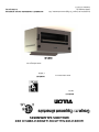
INSTALLATION & OPERATION MANUAL FOR
Salamander Broilers
MODELS
36ESB
www.vulcanhart.com
MODELS
C36ESB
www.wolfrange.com
36ESB

FORM F-47201 (06-14) PRINTED IN THE U.S.A.
- 2 -
IMPORTANT FOR YOUR SAFETY
THIS MANUAL HAS BEEN PREPARED FOR PERSONNEL QUALIFIED TO
INSTALL ELECTICAL EQUIPMENT, WHO SHOULD PERFORM THE INITIAL
FIELD START-UP AND ADJUSTMENTS OF THE EQUIPMENT COVERED BY THIS
MANUAL.
FOR YOUR SAFETY
DO NOT STORE OR USE GASOLINE OR OTHER
FLAMMABLE VAPORS OR LIQUIDS IN THE VICINITY OF
THIS OR ANY OTHER APPLIANCE.
WARNING: IMPROPER INSTALLATION, ADJUSTMENT,
ALTERATION, SERVICE OR MAINTENANCE CAN
CAUSE PROPERTY DAMAGE, INJURY OR DEATH.
READ THE INSTALLATION, OPERATING AND
MAINTENANCE INSTRUCTIONS THOROUGHLY BEFORE
INSTALLING OR SERVICING THIS EQUIPMENT.
IN THE EVENT OF A POWER FAILURE, DO NOT
ATTEMPT TO OPERATE THIS DEVICE.

FORM F-47201 (06-14) PRINTED IN THE U.S.A.
- 3 -
INSTALLATION, OPERATION AND CARE OF
ELECTRIC SALAMANANDER BROILERS
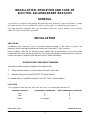
GENERAL
Your broiler is produced with quality workmanship and material. Proper installation, usage
and maintenance of your broiler will result in many years of satisfactory performance.
The manufacturer suggests that you thoroughly read this entire manual and carefully
follow all of the instructions provided.
INSTALLATION
UNPACKING
Immediately after unpacking, check for possible shipping damage. If the broiler is found to be
damaged, save the packaging material and contact the carrier within 7 days of delivery.
Before installing, verify that the electrical service agrees with the specifications on the rating plate
located under the crumb tray on the right side. If the supply and equipment requirements do not agree,
contact your dealer or Hobart Food Equipment Group Canada immediately.
INSTALLATION CODES AND STANDARDS
Your Vulcan broiler must be installed in accordance with:
1. State and local codes, or in the absence of local codes, with:
2. National Electrical Code ANSI/NFPA-70 (latest edition).
In Canada refer to Canadian Electrical Code C22.1 Part 1 (latest edition).
LOCATION
The equipment area must be kept free and clear of combustible substances.
Minimum Clearance
Combustible Construction
Non-Combustible Construction
Rear
2”
0”
Sides
6”
0”
Bottom
4” with legs
0”

FORM F-47201 (06-14) PRINTED IN THE U.S.A.
- 4 -
ELECTRICAL CONNECTIONS
WARNING: ELECTRICAL AND GROUNDING CONNECTIONS MUST COMPLY WITH
THE APPLICABLE PORTIONS OF THE NATIONAL ELECTRICAL CODE AND/OR OTHER
LOCAL ELECTRICAL CODES.
WARNING: DISCONNECT THE ELECTRICAL POWER SUPPLY AND PLACE A TAG AT
THE DISCONNECT SWITCH TO INDICATE THAT YOU ARE WORKING ON THE CIRCUIT.
ESB36 Broiler
Bring the broiler leads down through the wire chase located on the rear of the range, and connect the
terminal as required to the electrical supply. It may be necessary to remove the ¼-20 screw that retains
the wire panel to the broiler in order to properly feed the wires through the rear. Refer to the wiring
diagram of the broiler.
All required broiler wiring diagrams are packaged separately in a clear plastic bag and shipped with the
broiler.
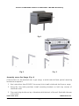
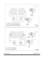
ASSEMBLY
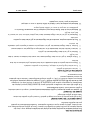
Salamander Broiler Mounted on a Wall (Fig. 1).
The separate wall mounting bracket accessory (WALLMNT-CHRBKR) will be needed to
wall mount the unit.
1. Follow the combustible/noncombustible clearance guidelines that are listed in the
“Installation” section in this manual.
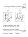
2. Make sure brackets are level and properly spaced so that bracket holes will align
with the threaded holes on the bottom of the unit to be mounted. The short leg of the
bracket with the holes that are nearest the elbow bend is to be placed against the
wall. (Fig. 2)
3. Secure brackets to wall by means of lag screws or bolts. (Fig. 2)
4. Mount the brackets only in the upside-down “L” position as shown. (Fig. 2)
5. Make sure the lag bolts or screws engage wall studs. Ensure that the wall
construction is of the type that will support the salamander weight.
6. Place the salamander into position on the brackets, making sure that the unit’s
bottom threaded attachment points are aligned with the holes in the brackets.(Fig. 3)
7. Secure unit into position with 3/8” bolts at the bottom of t he unit.
Thread the bolts through the holes in the brackets and into the threaded attachment
points on the bottom of the unit. (Fig. 3)

FORM F-47201 (06-14) PRINTED IN THE U.S.A.
- 5 -
Electric Salamander shown on WALLMNT-CHRBKR Accessory
Fig. 1
Fig. 2 Fig. 3
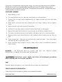
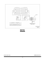
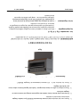
Assembly over a Gas Range (Fig. 4)
If the broiler is to be mounted over a gas range, a reinforced shelf and special mounting
brackets are required.
1. Use Instructions from RSHELF Accessory kit to install reinforced shelf over a range.
2. Using the four bolts provided, install mounting brackets on both top corners of
reinforced shelf.
3. Place and align broiler on top of brackets with the back of the unit flush with the rear
of the shelf.

FORM F-47201 (06-14) PRINTED IN THE U.S.A.
- 6 -
4. Install 3/8-16 Bolts through underside of the RSHELF.
Electric Salamander shown on RSHELF Accessory
Fig. 4
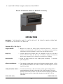
OPERATION
WARNING: THE BROILER AND ITS PARTS ARE HOT. BE CAREFUL WHEN OPERATING,
CLEANING OR SERVICING THE BROILER.
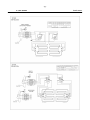
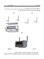
Controls (Fig. 5 & Fig. 6)
Angled Handle — Elevates or lowers the broiling grid to different positions. Grasp the
handle and pull towards broiler cavity. This releases the mechanism
and allows the lifting handle to move into the desired position.
Drip Tray — Collects grease and waste which is diverted by the tilt of the drip
shield. DO NOT allow the drip tray to overflow. Empty the drip tray
when three-quarters full to reduce the possibility of spillage.
Rack Handle — Glides the grid forward for easy loading and unloading. To operate,
pull straight out.
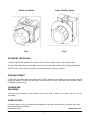
Infinite Load Switches — Two switches independently control the left and right heating elements in 208,
240, 220/380 and 240/415 volt models. Provides a variable range of on time
from 22% to 100%.
3-Heat, 4-Position Switch — Controls both elements on 480 volt models. Provides approximately 100% of
total available power (6 KW) at HI position, 50% at MED position, 25% at LO
position, and 0% at OFF position. The left side element is slightly longer than the
right side element and has a higher KW rating than the right side (3.150 vs.
2.850 KW).

FORM F-47201 (06-14) PRINTED IN THE U.S.A.
- 7 -
Infinite Load Switch 3-Heat, 4-Position Switch
Fig. 5 Fig. 6
OPERATING THE BROILER
To place 208/240 volt broilers into operation, turn the infinite switch knob to the desired setting.
To place 480 volt broilers into operation, turn the 3-heat, 4-position switch knob to the desired setting.
Wait 5 minutes for the broiler to preheat, than follow normal cooking procedures.
GRID ADJUSTMENT
Position the grid farther away from the burners for thick meats and for melting cheese or butter to avoid
drying the product. Position the grid closer to the burners for bacon, toast and quick heating. Watch
carefully to avoid burning.
LOADING AND
UNLOADING
Pull rack out far enough to load product. Push rack back in place for cooking. Pull rack out for
unloading.
POWER OUTAGE
If a power outage occurs, the broiler will automatically shut down. When power is restored, the broiler
will automatically start heating.

FORM F-47201 (06-14) PRINTED IN THE U.S.A.
- 8 -
If the broiler is left unattended during the power outage, turn either the infinite switch knob (220/380 &
208/240 volt) or the 3-heat, 4-position switch knob (480 volt) to the OFF position. When power is
restored, turn control knob back to ON position. The broiler will be preheated in 5 minutes and normal
cooking operation can then be resumed.
CARE AND CLEANING
1. Allow broiler to cool.
2. To remove broiler rack for cleaning, raise broiler to center position.
3. Position left and right hands simultaneously on edges of broiler rack and raise both
rack stops.
4. Slide broiler rack and drip tray forward past rack stops, holding tray up against
racks.
5. Remove broiler rack and drip tray from broiler.
6. Let back of tray drop down to vertical to allow front hooks to disengage.
7. Remove drip pan from broiler rack and clean as you would any normal utensil.
8. To replace, hook the drip tray to the broiler rack while tray is in a vertical position.
9. Replace broiler rack and drip tray in side channels while holding tray up close to
rack.
10. Clean bottom pan. Slide pan out and wash with soap and water. Rinse thoroughly
and wipe dry with a soft clean cloth.
11. Clean stainless steel surfaces using a damp cloth or with a commercial stainless
steel cleaner.
MAINTENANCE
WARNING: THE BROILER AND ITS PARTS ARE HOT. BE CAREFUL WHEN
OPERATING, CLEANING OR SERVICING THE BROILER.
Disconnect power supply and follow lockout/tagout procedures
before cleaning and servicing the appliance.
VENT
Annually, when the broiler is cool, check the flue and clear any obstructions.
SERVICE AND PARTS INFORMATION
Contact your local Service Agency to obtain service and parts information.

FORM F-47201 (06-14) PRINTED IN THE U.S.A.
- 9 -

FORM F-47201 (06-14) PRINTED IN THE U.S.A.
- 10 -
NOTES

F-47201 (06-14) IMPRIMÉ AUX É.-U.
- 11 -
NOTES

F-47201 (06-14) IMPRIMÉ AUX É.-U.
- 10 -

F-47201 (06-14) IMPRIMÉ AUX É.-U.
- 9 -
ENTRETIEN
AVERTISSEMENT : LE GRILLOIR ET SES COMPOSANTS SONT CHAUDS. SOYEZ PRUDENTS
LORSQUE VOUS L’UTILISEZ, LE NETTOYEZ OU EN FAITES L’ENTRETIEN.
Débranchez l’alimentation électrique et observez les normes
de verrouillage/étiquetage avant de nettoyer l’appareil et en faire l’entretien.
ÉVENT
À tous les ans, lorsque le gril est refroidi, vérifiez la cheminée et nettoyez toutes les
obstructions.
INFORMATIONS SUR LE SERVICE TECHNIQUE ET LES PIÈCES DE RECHANGE
Contactez l’agence de service de votre région pour l’entretien et les pièces de rechange.

F-47201 (06-14) IMPRIMÉ AUX É.-U.
- 8 -
RÉGLAGE DU GRIL
Pour éviter d’assécher les produits, placez le gril plus loin des brûleurs lorsque vous cuisez des
viandes épaisses et pour faire fondre le fromage ou le beurre. Placez le gril plus près des brûleurs pour
cuire le bacon, griller les toasts et pour réchauffer rapidement. Surveillez attentivement les produits
pour les empêcher de brûler.
CHARGEMENT ET DÉCHARGEMENT
Tirez le gril assez proche de vous pour charger le produit. Poussez le gril en position de cuisson.
Faites sortir le gril pour décharger.
PANNE DE COURANT
S’il survient une panne de courant, le grilloir s’éteindra automatiquement. Lorsque le courant reviendra,
le grilloir commencera à chauffer immédiatement.
Si le grilloir doit rester sans surveillance pendant la panne de courant, faites tourner le bouton des
interrupteurs (à progression continue pour les tensions de 220/380 & 208/240 volts et à 4 réglages
pour la tension de 480 volts) à la position d’ARRÊT (OFF). Lorsque le courant reviendra, tournez les
boutons en position de MARCHE (ON). Le grilloir sera préchauffé pendant 5 minutes et les opérations
de cuisson normales pourront
alors recommencer.
ENTRETIEN ET NETTOYAGE
1. Laissez refroidir le grilloir.
2. Pour retirer le gril pour le nettoyer, élevez-le en position centrale.
3. Placez vos mains gauche et droite ensemble sur les deux bords du gril et soulevez-en les deux
butées.
4. Faites glisser le gril et son bac d’égouttement en avant des butées en tenant le bac
sur le gril.
5. Retirez le gril et le bac d’égouttement du grilloir.
6. Laissez l’arrière du bac descendre à la verticale pour dégager les crochets avant.
7. Retirez le bac d’égouttement du gril et nettoyez-le comme n’importe quel ustensile
de cuisine.
8. Pour le remettre en place, accrochez le bac d’égouttement au gril, le bac étant en position
verticale.
9. Replacez le gril et le bac d’égouttement dans les guides latéraux tout en tenant le
bac près du gril.
10. Nettoyez le bac du fond. Sortez le bac pour le nettoyer à l’eau savonneuse. Rincez-le en
profondeur et essuyez-le avec un chiffon doux propre.
11. Nettoyez les surfaces en inox à l’aide d’un chiffon humide ou avec un nettoyant
commercial pour l’acier inoxydable.

F-47201 (06-14) IMPRIMÉ AUX É.-U.
- 7 -
La poignée du tiroir — Elle fait glisser le tiroir vers l’avant pour le charger et le décharger
facilement. Pour la faire fonctionner, tirez directement vers
l’extérieur.
Interrupteurs à
progression continue — Deux interrupteurs contrôlent séparément les éléments chauffants de
gauche et de droite des modèles dont les tensions sont de 208, 240,
220/380 et 240/415 volts. Ils donnent une plage de chauffe active variant
de 22 à 100%.
3 Interrupteurs de
chauffe à 4 réglages — Ils contrôlent les deux éléments des modèle à tension de 480 volts. Ils
fournissent environ 100% de la puissance disponible au réglage HI (6
kW), 50% au réglage MED, 25% au réglage LO, et 0% au réglage OFF
(ARRÊT). L’élément de gauche est légèrement plus long que celui de
droite et possède une puissance en kW plus élevée que le droit (3,150 vs
2,850 kW).
Interrupteur à progression continue 3 interrupteurs à 4 réglages
Fig. 5 Fig. 6
POUR METTRE LE GRILLOIR EN FONCTION
Pour les tensions de 208/240 volts, amenez le bouton de l’interrupteur à progression continue au
réglage souhaité.
Pour la tension de 480 volts, faites tourner le bouton de l’interrupteur à 4 intensités vers le réglage
souhaité.
Attendez pendant 5 minutes que le grilloir soit bien préchauffé et ensuite, suivez le processus normal
de cuisson.

F-47201 (06-14) IMPRIMÉ AUX É.-U.
- 6 -
1. Servez-vous des instructions de la trousse d’accessoire RSSHELF pour installer l’étagère
renforcée au-dessus de la cuisinière.
2. À l’aide des quatre boulons livrés, installez les supports de montage sur les deux coins de
l’étagère renforcée.
3. Placez et alignez le grilloir au-dessus des supports, l’arrière de l’appareil étant au même niveau
que l’arrière de l’étagère.
4. Vissez les boulons de ⅜ - 16 à travers le dessous de l’étagère RSHELF.
Salamandre électrique illustrée montée sur l’accessoire RSHELF
Fig. 4
FONCTIONNEMENT
AVERTISSEMENT : LE GRILLOIR ET SES COMPOSANTS SONT CHAUDS. SOYEZ PRUDENT
LORSQUE VOUS UTILISEZ, NETTOYEZ OU ENTRETENEZ LA SALAMANDRE.
Les commandes (Fig. 5 & Fig. 6)
La poignée angulaire — Elle sert à élever ou abaisser le tiroir de grillage à différentes positions.
Saisissez la poignée et poussez-la vers l’intérieur de la cavité du grilloir.
Cela déclenche le mécanisme et permet à la poignée de levage de se
déplacer à la position souhaitée.
Le bac d’égouttement — Il capte la graisse et les rebuts détournés par la pente de l’écran
d’égouttement. NE LAISSEZ PAS le bac d’égouttement déborder.
Vidangez-le quand il est au . rempli pour réduire les risques de
déversement.

F-47201 (06-14) IMPRIMÉ AUX É.-U.
- 5 -
7. Fixez solidement l’appareil en position à l’aide de boulons de ⅜ po (9,5 mm) en
dessous de l’unité. Vissez les boulons à travers les trous des supports et dans les
points d’attache taraudés du dessous de l’appareil (Fig. 3).
Salamandre électrique illustrée fixée avec l’accessoire WALLMNT-CHRBKR
Fig. 1
Fig. 2 Fig. 3
Montage au-dessus d’une cuisinière au gaz (Fig. 4)
Si le grilloir doit être monté au-dessus d’une cuisinière au gaz, une étagère renforcée et des supports
de fixation spéciaux sont nécessaires.

F-47201 (06-14) IMPRIMÉ AUX É.-U.
- 4 -
CONNEXIONS ÉLECTRIQUES
AVERTISSEMENT : LES CONNEXIONS ÉLECTRIQUES ET DE MISE À LA TERRE
DOIVENT ÊTRE CONFORMES AUX PORTIONS APPLICABLES DU CODE NATIONAL
ÉLECTRIQUE ET/OU DE TOUS LES AUTRES CODES ÉLECTRIQUES LOCAUX.
AVERTISSEMENT : DÉBRANCHEZ LA SOURCE D’ALIMENTATION ÉLECTRIQUE ET
APPOSEZ UNE ÉTIQUETTE SUR LE SECTIONNEUR POUR SIGNALER QUE VOUS
TRAVAILLEZ SUR LE CIRCUIT.
Le grilloir ESB36
Passez les fils du grilloir dans le cache-fils situé à l’arrière de la cuisinière et raccordez les bornes
requises à l’alimentation électrique. Il se peut qu’il soit nécessaire de retirer la vis . - 20 qui retient le
bloc porte fils au grilloir pour pouvoir passer les fils correctement à travers l’arrière. Référez-vous au
schéma de câblage du grilloir.
Tous les schémas de câblage requis sont emballés séparément dans un sac de plastique transparent
et livrés en même temps que le grilloir.
MONTAGE
Grilloir salamandre fixé au mur (Fig. 1).
Pour monter l’appareil sur un mur, il faudra vous procurer un accessoire de support au mur
(WALLMNT-CHRBKR).
1. Observez les directives de dégagement combustible/incombustible énumérées à la
rubrique « Installation » de ce guide d’installation.
2. Assurez-vous que les supports de montage soient de niveau et espacés
correctement de sorte que les trous des supports s’alignent avec les trous taraudés
au-dessous de l’appareil que vous devez monter. La partie courte du support dont
les trous se situent le plus près de la courbure du coude doit être placée contre le
mur (Fig. 2).
3. Fixez solidement les supports au mur en vous servant de tirefonds ou de boulons
(Fig. 2).
4. Monter d’abord les supports en position de « L » inversé tel qu’illustré (Fig. 2).
5. Assurez-vous que les tirefonds ou les boulons vont se visser dans les montants
muraux. Assurez-vous également que le type de construction du mur
peut supporter le poids de la salamander.
6. Posez la salamandre en position sur les supports en veillant à ce que les points
d’attache taraudés au-dessous de l’appareil soient alignés avec les trous des
supports (Fig. 3).

F-47201 (06-14) IMPRIMÉ AUX É.-U.
- 3 -
INSTALLATION, FONCTIONNEMENT ET ENTRETIEN
DES GRILLOIRS SALAMANDRES ÉLECTRIQUES
INFORMATIONS GÉNÉRALES
Votre grilloir a été construit avec des matériaux et une main d’oeuvre de qualité. Une
bonne installation, l’utilisation et l’entretien appropriés de votre salamandre vous
apporteront plusieurs années de performances satisfaisantes.
Le fabricant vous conseille de lire attentivement tout ce manuel et de suivre minutieusement toutes les
consignes qu’il contient.
INSTALLATION
DÉBALLAGE
Aussitôt après le déballage, assurez-vous que l’appareil n’a pas subi de dommages pendant son
transport. Si le grilloir a été endommagé, gardez le matériel d’emballage et contactez le transporteur
dans les 7 jours de la livraison.
Avant l’installation, assurez-vous que l’entrée électrique concorde avec les spécifications de la plaque
signalétique fixée sur le bac à miettes du côté droit. Si la tension de l’entrée électrique et celle de
l’appareil ne concordent pas, contactez votre détaillant ou le Groupe Hobart Canada Équipement
alimentaire immédiatement.
CODES ET NORMES D’INSTALLATION
Votre grilloir Vulcan doit être installé en conformité avec :
1. Les codes des états et les codes locaux ou en leur absence avec :
2. Le Code national électrique ANSI/NFPA-70 (édition la plus
récente).
Au Canada, référez-vous au Code électrique canadien, partie 1 de la norme C22,1 (édition la plus
récente).).
EMPLACEMENT
L’espace autour de cet appareil doit être dégagé et exempt de toute substance
combustible.
Minimum Clearance
Combustible Construction
Non-Combustible Construction
Rear
2”
0”
Sides
6”
0”
Bottom
4” with legs
0”

F-47201 (06-14) IMPRIMÉ AUX É.-U.
- 2 -
MESURES DE SÉCURITÉ IMPORTANTES
CE MANUEL A ÉTÉ PRÉPARÉ À L’INTENTION D’UN PERSONNEL QUALIFIÉ ET
AUTORISÉ À INSTALLER DES APPAREILS FONCTIONNANT AU GAZ ET À
EFFECTUER LE DÉMARRAGE INITIAL CHEZ LE CLIENT DE MÊME QUE LE
RÉGLAGE DES APPAREILS CONCERNÉS DANS CE MANUEL.
MESURE DE SÉCURITÉ
NE PAS RANGER NI UTILISER DE L’ESSENCE NI TOUT
AUTRE LIQUIDE OU VAPEUR INFLAMMABLE À
PROXIMITÉ DE CET APPAREIL OU DE TOUT AUTRE
APPAREIL.
L’INSTALLATION, LE RÉGLAGE, LA MODIFICATION ET
L’ENTRETIEN INCORRECTS DE CET APPAREIL
PEUVENT CAUSER DES DOMMAGES MATÉRIELS, DES
BLESSURES ET MÊME LA MORT. LIRE LES
INSTRUCTIONS D’INSTALLATION, DE
FONCTIONNEMENT ET D’ENTRETIEN AVANT DE
PROCÉDER À TOUTE INSTALLATION OU TOUT
ENTRETIEN.
IN EN CAS DE PANNE DE COURANT, NE PAS
FAIRE FONCTIONNER CET APPAREIL.
La page est en cours de chargement...
-
 1
1
-
 2
2
-
 3
3
-
 4
4
-
 5
5
-
 6
6
-
 7
7
-
 8
8
-
 9
9
-
 10
10
-
 11
11
-
 12
12
-
 13
13
-
 14
14
-
 15
15
-
 16
16
-
 17
17
-
 18
18
-
 19
19
-
 20
20
-
 21
21


VULCAN & WOLF 36ESB C36ESB Salamander Broiler Le manuel du propriétaire
- Catégorie
- Cuisinières
- Taper
- Le manuel du propriétaire
- Ce manuel convient également à
dans d''autres langues
Autres documents
-
Vulcan 36RB Manuel utilisateur
-
-
Vulcan 36C-6B Le manuel du propriétaire
-
Vulcan V Series HDR Broiler Mode d'emploi
-
Vulcan-Hart VB73 Manuel utilisateur
-
Vulcan 36S-36CB Le manuel du propriétaire
-
Garland 36ER36 Mode d'emploi
-
Garland E20 Series Owner Instruction Manual
-
-