
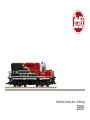
Modell der Diesellok Alco - NS Hilfszug
29911

2

3
Inhaltsverzeichnis: Seite
Sicherheitshinweise 4
Wichtige Hinweise 4
Funktionen 4
Betriebshinweise 4
Multiprotokollbetrieb 5
Wartung und Instandhaltung 6
Schaltbare Funktionen 6
CV -Tabelle 7
Bilder 28
Ersatzteile 30
Table of Contents: Page
Safety Notes 8
Important Notes 8
Functions 8
Information about operation 8
Multi-Protocol Operation 9
Service and maintenance 10
Controllable Functions 10
Table for CV 11
Figures 28
Spare parts 30
Inhoudsopgave: Pagina
Veiligheidsvoorschriften 16
Belangrijke aanwijzing 16
Functies 16
Bedrijfsaanwijzingen 16
Multiprotocolbedrijf 17
Onderhoud en handhaving 18
Schakelbare functies 18
CV 19
Afbeeldingen 28
Onderdelen 30
Indice del contenuto: Pagina
Avvertenze per la sicurezza 24
Avvertenze importanti 24
Funzioni 24
Avvertenze per ilfunzionamento 24
Esercizio multi-protocollo 25
Manutenzione ed assistere 26
Funzioni commutabili 26
CV 27
Figures 28
Pezzi di ricambio 30
Sommaire : Page
Remarques importantes sur la sécurité 12
Information importante 12
Fonctionnement 12
Remarques sur l’exploitation 12
Mode multiprotocole 13
Entretien et maintien 14
Fonctions commutables 14
CV 15
Images 28
Pièces de rechange 30
Indice de contenido: Página
Aviso de seguridad 20
Notas importantes 20
Funciones 20
Instrucciones de uso 20
Funcionamiento multiprotocolo 21
El mantenimiento 22
Funciones commutables 22
CV 23
Figuras 28
Recambios 30

4
Sicherheitshinweise
• Das Modell darf nur mit einem dafür bestimmten
Betriebssystem eingesetzt werden.
• Nur Schaltnetzteile und Transformatoren verwenden,
die Ihrer örtlichen Netzspannung entsprechen.
• Das Modell darf nur aus einer Leistungsquelle versorgt werden.
• Beachten Sie unbedingt die Sicherheitshinweise in der Bedienungsanleitung zu
Ihrem Betriebssystem.
• Nicht für Kinder unter 15 Jahren.
• ACHTUNG! Funktionsbedingte scharfe Kanten und Spitzen.
• ACHTUNG! Dieses Produkt enthält Magnete. Das Verschlucken von mehr als einem
Magneten kann unter Umständen tödlich wirken. Gegebenenfalls ist sofort ein Arzt
aufzusuchen.
Wichtige Hinweise
• Wegen der hohen Leistungsaufnahme dieser Lokomotive (dieses Modells) ist der
Betrieb mit der Mobile Station nicht möglich.
• Die Bedienungsanleitung ist Bestandteil des Produktes und muss deshalb aufbe-
wahrt sowie bei Weitergabe des Produktes mitgegeben werden.
• Gewährleistung und Garantie gemäß der beiliegenden Garantieurkunde.
• Für Reparaturen oder Ersatzteile wenden Sie sich bitte an Ihren LGB-Fachhändler.
• Entsorgung: www.maerklin.com/en/imprint.html
Funktionen
• Das Modell ist für den Betrieb auf LGB-Zweileiter-Gleichstrom-Systemen mit
herkömmlichen LGB-Gleichstrom-Fahrpulten vorgesehen (DC, 0 – 24 V).
• Werkseitig eingebauter Multiprotokoll-Decoder (DC, DCC, mfx).
• Zum Einsatz mit dem LGB-Mehrzugsystem (DCC) ist das Modell auf Lokadresse 03
programmiert. Im Betrieb mit mfx wird die Lok automatisch erkannt.
• Mfx-Technologie für Mobile Station/Central Station.
Name ab Werk: NS 5642 / Tank Car
• Die Funktionen können nur parallel aufgerufen werden. Die seriealle Funktionsaus-
lösung ist nicht möglich (beachten Sie hierzu die Anleitung zu Ihrem Steuergerät).
• Die Lok ist nicht auf Oberleitungsbetrieb umschaltbar.
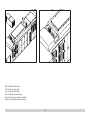
Betriebsartenschalter
Das Modell hat einen vierstugen Betriebsarten–Schalter im Führerstand (Bild 1 & 2).
Pos. 0 Lok stromlos abgestellt
Pos. 1 Lokmotor, Beleuchtung und Sound eingeschaltet
Pos. 2 wie Position 1
Pos. 3 wie Position 1
Elektronischer Sound
Die Lok ist mit einem Lautstärkeregler ausgestattet. Der Lautstärkeregler ist neben
dem Betriebsartenschalter angeordnet (Bild 1).
Glocke und Horn können mit dem beiliegenden LGB-Sound-Schaltmagneten (17050)
ausgelöst werden. Der Schaltmagnet lässt sich zwischen die Schwellen der meisten
LGB-Gleise klipsen.
Der Magnet bendet sich seitlich versetzt unter dem eingeprägten LGB-Logo. Platzie-
ren Sie den Magneten auf einer Seite, um das Horn auszulösen, wenn die Lok diese
Stelle überquert. Bei Anordnung auf der anderen Seite ertönt die Glocke.
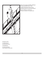
Tankwagen
Der Tankwagen ist mit einer Wasserpumpe ausgerüstet, die über den Decoder im
Wagen geschaltet werden kann.
Der Kessel darf nur mit sauberem und kaltem Wasser befüllt werden (siehe Bild 3).
Hinweis: Um Beschädigungen zu vermeiden darf die Pumpe nur betrieben werden,
solange Wasser im Kessel ist.
Allgemeiner Hinweis zur Vermeidung elektromagnetischer Störungen:
Um den bestimmungsgemäßen Betrieb zu gewährleisten, ist ein permanenter,
einwandfreier Rad-Schiene-Kontakt der Fahrzeuge erforderlich.Führen Sie keine
Veränderungen an stromführenden Teilen durch.

5
Multiprotokollbetrieb
Analogbetrieb
Der Decoder kann auch auf analogen Anlagen oder Gleisabschnitten betrieben wer-
den. Der Decoder erkennt die analoge Gleichspannung (DC) automatisch und passt
sich der analogen Gleisspannung an. Es sind alle Funktionen, die unter mfx oder DCC
für den Analogbetrieb eingestellt wurden aktiv (siehe Digitalbetrieb).
Die Eingebauten Sound-Funktionen sind ab Werk im Analogbetrieb nicht aktiv.
Digitalbetrieb
Der Decoder ist ein Multiprotokolldecoder. Der Decoder kann unter folgenden Digital-
Protokollen eingesetzt werden: mfx oder DCC.
Das Digital-Protokoll mit den meisten Möglichkeiten ist das höchstwertige Digital-
Protokoll. Die Reihenfolge der Digital-Protokolle ist in der Wertung fallend:
Priorität 1: mfx; Priorität 2: DCC; Priorität 3: DC
Hinweis: Digital-Protokolle können sich gegenseitig beeinussen. Für einen stö-
rungsfreien Betrieb empfehlen wir, nicht benötigte Digital-Protokolle mit Congura-
tions Variable (CV) 50 zu deaktivieren.
Deaktivieren Sie, sofern dies Ihre Zentrale unterstützt, auch dort die nicht benötigten
Digital-Protokolle.
Werden zwei oder mehrere Digital-Protokolle am Gleis erkannt, übernimmt der De-
coder automatisch das höchstwertige Digital-Protokoll, z.B. mfx/DCC, somit wird das
mfx-Digital-Protokoll vom Decoder übernommen.
Hinweis: Beachten Sie, dass nicht alle Funktionen in allen Digital-Protokollen möglich
sind. Unter mfx und DCC können einige Einstellungen von Funktionen, welche im
Analog-Betrieb wirksam sein sollen, vorgenommen werden.
Hinweise zum Digitalbetrieb
• Die genaue Vorgehensweise zum Einstellen der diversen CVs entnehmen Sie bitte
der Bedienungsanleitung Ihrer Mehrzug-Zentrale.
• Die ab Werk eingestellten Werte sind für mfx gewählt, so dass ein bestmöglichstes
Fahrverhalten gewährleistet ist.
Für andere Betriebssysteme müssen gegebenenfalls Anpassungen getätigt
werden.
mfx-Protokoll
Adressierung
• Keine Adresse erforderlich, jeder Decoder erhält eine einmalige und eindeutige
Kennung (UID).
• Der Decoder meldet sich an einer Central Station oder Mobile Station mit seiner
UID-Kennung automatisch an.
Programmierung
• Die Eigenschaften können über die grasche Oberäche der Central Station bzw.
teilweise auch mit der Mobile Station programmiert werden.
• Es können alle CV mehrfach gelesen und programmiert werden.
• Die Programmierung kann entweder auf dem Haupt- oder dem Programmiergleis
erfolgen.
• Die Defaulteinstellungen (Werkseinstellungen) können wieder hergestellt werden.
• Funktionsmapping: Funktionen können mit Hilfe der Central Station 60212 (einge-
schränkt) und mit der Central Station 60213/60214/60215/60216/60226 beliebigen
Funktionstasten zugeordnet werden (Siehe Hilfe in der Central Station).
DCC-Protokoll
Adressierung
• Kurze Adresse – Lange Adresse – Traktionsadresse
• Adressbereich:
1 – 127 kurze Adresse, Traktionsadresse
1 – 10.239 lange Adresse
• Jede Adresse ist manuell programmierbar.
• Kurze oder lange Adresse wird über die CV 29 ausgewählt.
• Eine angewandte Traktionsadresse deaktiviert die Standard-Adresse.
Programmierung
• Die Eigenschaften können über die Conguration Variablen (CV) mehrfach geän-
dert werden.
• Die CV-Nummer und die CV-Werte werden direkt eingegeben.
• Die CVs können mehrfach gelesen und programmiert werden (Programmierung
auf dem Programmiergleis).
• Die CVs können beliebig programmiert werden (PoM - Programmierung auf dem
Hauptgleis). PoM ist nicht möglich bei den CV 1, 17, 18 und 29. PoM muss von Ihrer
Zentrale unterstützt werden (siehe Bedienungsanleitung ihres Gerätes).
• Die Defaulteinstellungen (Werkseinstellungen) können wieder hergestellt werden.
• 14 bzw. 28/128 Fahrstufen einstellbar.
• Alle Funktionen können entsprechend dem Funktionsmapping geschaltet werden.
• Weitere Information, siehe CV-Tabelle DCC-Protokoll.
Es wird empfohlen, die Programmierungen grundsätzlich auf dem Programmiergleis
vorzunehmen.

6
WARTUNG
Schmierung
Die Achslager hin und wieder mit je einem Tropfen MärklinÖl (7149) ölen.
Austauschen der Glühlampen
Lampen: Lampengehäuse vom Modell abziehen. Eingesteckte Glühlampe aus dem
Sockel ziehen. Neue Glühlampe einstecken. Modell wieder zusammenbauen.
Innenbeleuchtung: Glühlampe mit einer Pinzette aus der Fassung ziehen. Neue
Glühlampe einstecken.
Austauschen des Haftreifens
Das Getriebe sollte ausgebaut werden, um den Haftreifen auszutauschen:
• Auf der Unterseite des Getriebes sind sechs Schrauben. Erste und letzte Schraube
lösen.
• Getriebe vorsichtig aus dem Fahrgestell ziehen.
• Mit einem kleinen achen Schraubendreher den alten Haftreifen entfernen:
• Den alten Haftreifen aus der Rille (Nut) im Treibrad hebeln.
• Vorsichtig den neuen Haftreifen über das Rad schieben und in die Rille (Nut) des
Rads einsetzen.
• Überprüfen, dass der Haftreifen richtig sitzt.
• Modell wieder zusammenbauen.
Schaltbare Funktionen Lokomotive
Beleuchtung 2LV + LR
Geräusch: Horn lang 1 Sound 1
Geräusch: Bremsenquietschen aus 2 BQ
Geräusch: Horn kurz 3 Sound 2
Geräusch: Horn Signal vor Bahnübergang 4
Sound 12
Geräusch: Kompressor 5 Sound 11
Geräusch: Betriebsgeräusch 2, 3 6 FS
Geräusch: Glocke 7 Sound 3
Sound an/aus 8
ABV, aus 9
Rangierlicht doppel A 10 LV + LR
Blinklicht 11 AUX 2
Fernlicht 12 AUX 3
Geräusch: Sanden 13 Sound 15
Nummernschild-Beleuchtung 14 AUX 4
Geräusch: Ansage 15 Sound 4
Geräusch: Ansage 16 Sound 5
Geräusch: Horn, 4 x kurz 17 Sound 13
Geräusch: Druckluft ablassen 18 Sound 14
Geräusch: Schienenstöße 19 Sound 16
Geräusch: Ankuppeln (Puffer an Puffer) 20 Sound 17
Geräusch: Wasserpumpe mit Dieselaggregat 21 Sound 22
Geräusch: Kesselwagen füllen 22 Sound 23
Geräusch: Feuerwehrsirene 23 Sound 18
Geräusch: Ansage 24 Sound 6
Geräusch: Gespräch 25 Sound 19
Geräusch: Gespräch 26 Sound 20
Geräusch: Gespräch 27 Sound 21
Schaltbare Funktionen Tankwagen
Wasserpumpe an/aus 11
1Funktion nur im Digitalbetrieb möglich
2im Analogbetrieb aktiv
3mit Zufallsgeräuschen

7
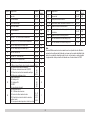
Register Belegung Bereich Default
1 Adresse 1 – 127 3
2 Minimalgeschwindigkeit 0 – 255 8
3 Anfahrverzögerung 0 – 71 6
4 Bremsverzögerung 0 – 71 6
5 Maximalgeschwindigkeit 0 – 255 205
8 Reset 8 159
13 Funktion F1 – F8 bei alternativem Gleissignal 0 – 255 32
14 Funktion FL, F9 – F15 bei alternativem Gleissignal 0 – 255 1
17 erweiterte Adresse, höherwertiges Byte 192 – 231 192
18 erweiterte Adresse, niederwertiges Byte 0 – 255 128
19 Traktionsadresse 0 – 255 0
21 Funktionen F1 – F8 bei Traktion 0 – 255 0
22 Funktionen FL, F9 – F15 bei Traktion 0 – 255 0
27 Bit 4: Bremsmodus Spannung gegen die Fahrtrichtung
Bit 5: Bremsmodus Spannung mit der Fahrtrichtung
0/16
0/32 16
29
Bit 0: Fahrtrichtung normal/invers
Bit 1: Anzahl der Fahrstufen 14/28(128)
Bit 2: Analogbetrieb aus/an
Bit 5: kurze / lange Adresse aktiv
0/1
0/2
0/4
0/32
6
50
Alternative Formate
Bit 0: Analog AC
Bit 1: Analog DC
Bit 2: MM
Bit 3: mfx aus/an
0/1
0/2
0/4
0/8
14
60
Multibahnhofsansage
Bit 0 – 3: Anzahl der Bahnhöfe
Bit 4: Endansage wechselt die Reihenfolge
Bit 5: Lokrichtung wechselt die Reihenfolge
Bit 6: Vorgabe für Reihenfolge
0 – 15
0/16
0/32
0/64
1
Register Belegung Bereich Default
63 Lautstärke gesamt 0 – 255 255
64 Schwelle für Bremsenquietschen 0 – 255 15
67 – 94 Geschwindigkeitstabelle Fahrstufen 1 – 28 0 – 255
112 Mapping Licht vorne, Modus 0 – 21 1
113 Mapping Licht vorne, Dimmer 0 – 255 255
114 Mapping Licht vorne, Periode 0 – 255 20
176 Minimalgeschwindigkeit analog DC 1 – 255 50
177 Maximalgeschwindigkeit analog DC 1 – 255 120
Hinweis:
Unter www.LGB.de nden Sie ein Tool, mit dem Sie verschiedene Decodereinstel-
lungen berechnen können, sowie eine ausführliche Beschreibung des Decoders und
der Einstellungen. In dieser Anleitung ist auch das Programmieren der Decoderein-
stellungen mit dem Univeral-Handy-55015 erklärt.

8
Safety Notes
• This model may only be used with the operating system designed for it.
• Use only switched mode power supply units and transformers that are designed
for your local power system.
•This locomotive must never be supplied with power from more than one power pack.
• Pay close attention to the safety notes in the instructions for your operating system.
• Not for children under the age of 15.
• WARNING! Sharp edges and points required for operation.
• WARNING! This product contains magnets. Swallowing more than one magnet may
cause death in certain circumstances. If necessary, see a doctor immediately.
Important Notes
• Due to its high current draw, this locomotive (this model) cannot be operated with
the Mobile Station.
• The operating instructions are a component part of the product and must therefore
be kept in a safe place as well as included with the product, if the latter is given to
someone else.
• The warranty card included with this product species the warranty conditions.
• Please see your authorized LGB dealer for repairs or spare parts.
• Disposing: www.maerklin.com/en/imprint.html
Functions
• This model is designed for operation on LGB two-rail DC systems with conventio-
nal LGB DC train controllers or power packs (DC, 0 – 24 volts).
• Factory-installed multiple protocol decoder (DC, DCC, mfx).
•
The model is programmed with locomotive address 03 for use with the LGB Multi
Train System (DCC). The locomotive is automatically recognized in operation with mfx.
• Mfx technology for the Mobile Station/Central Station.
Name set at the factory: NS 5642 / Tank Car
• The functions can be activated only in parallel. Serial activation of the functions is
not possible (Please note here the instructions for your controller).
• The locomotive cannot be switched to operation from catenary.
Mode of Operation Switch
This locomotive has a 4-position mode of operation switch (Figure 1 & 2).
Pos. 0 Locomotive stored on a siding without current
Pos. 1 Locomotive motor, lighting, and sound turned on
Pos. 2 Same as Position 1
Pos. 3 Same as Position 1
Sound
This locomotive has a volume controller. The volume controller is located next to the
mode of operation switch (Figure 1).
The bell and horn can be activated with the LGB sound activation magnet (17050) in-
cluded with the locomotive. The activation magnet can be clipped into place between
the ties of most LGB track sections.
The magnet is positioned to the side under the LGB logo cast into the plastic cover.
Place the magnet on one side to activate the horn when the locomotive passes over
this spot. The bell will sound when the magnet is placed on the other side.
Tankcar
The tank car is equipped with a water pump, which can be controlled using the
decoder in the car.
The tank may only be lled with clean, cold water (See Figure 3).
Note: To avoid damage, the pump may only be operated as long as there is water in
the tank.
General Note to Avoid Electromagnetic Interference:
A permanent, awless wheel-rail contact is required in order to guarantee operation
for which a model is designed. Do not make any changes to current-conducting parts.

9
Multi-Protocol Operation
Analog Operation
This decoder can also be operated on analog layouts or areas of track that are
analog. The decoder recognizes alternating current (DC) and automatically adapts
to the analog track voltage. All functions that were set under mfx or DCC for analog
operation are active (see Digital Operation).
The built-in sound functions come from the factory inactive for analog operation.
Digital Operation
The decoders are multi-protocol decoders. These decoders can be used under the
following digital protocols: mfx or DCC.
The digital protocol with the most possibilities is the highest order digital protocol.
The sequence of digital protocols in descending order is:
Priority 1: mfx; Priority 2: DCC; Priority 3: DC
Note: Digital protocols can inuence each other. For trouble-free operation, we re-
commend deactivating those digital protocols not needed by using CV 50. Deactivate
unneeded digital protocols at this CV if your controller supports this function.
If two or more digital protocols are recognized in the track, the decoder automatically
takes on the highest order digital protocol, example: mfx/DCC; the decoder takes on
the mfx digital protocol (see previous table).
Note: Please note that not all functions are possible in all digital protocols. Several
settings for functions, which are supposed to be active in analog operation, can be
done under mfx and DCC.
Notes on digital operation
• The operating instructions for your central unit will give you exact procedures for
setting the different parameters.
• The values set at the factory have been selected for mfx in order to guarantee the
best possible running characteristics.
Adjustments may have to be made for other operating systems.
mfx Protocol
Addresses
• No address is required; each decoder is given a one-time, unique identier (UID).
• The decoder automatically registers itself on a Central Station or a Mobile Station
with its UID-identier.
Programming
• The characteristics can be programmed using the graphic screen on the Central
Station or also partially with the Mobile Station.
• All of the Conguration Variables (CV) can be read and programmed repeatedly.
• The programming can be done either on the main track or the programming track.
• The default settings (factory settings) can be produced repeatedly.
• Function mapping: Functions can be assigned to any of the function buttons with the
help of the 60212 Central Station (with limitations) and with the 60213/60214/
60215/60216/60226 Central Station (See help section in the Central Station).
DCC Protocol
Addresses
• Short address – long address – multiple unit address
• Address range:
1 – 127 for short address and multiple unit address,
1 – 10.239 for long address
• Every address can be programmed manually.
• Short or long address is selected by means of CV 29 (Bit 5).
• A multiple unit address that is being used deactivates the standard address.
Programming
•
The characteristics can be changed repeatedly using the Conguration Variables (CV).
• The CV numbers and the CV values are entered directly.
• The CVs can be read and programmed repeatedly. (Programming is done on the
programming track.)
• The CVs can be programmed in any order desired. (PoM - Programming can be done
on the main track). PoM is not possible with CVs CV 1, 17, 18, and 29. PoM must be
supported by your central controller (Please see the description for this unit.).
• The default settings (factory settings) can be produced repeatedly.
• 14 or 28/126 speed levels can be set.
• All of the functions can be controlled according to the function mapping (see CV
description).
• See the CV description for the DCC protocol for additional information.
We recommend that in general programming should be done on the programming
track.

10
SERVICE
Lubrication
The axle bearings should be lubricated occasionally with a small amount of Märklin-
Oil (7149).
Replacing Light Bulbs
Lamps: Remove the lamp housing from the model. Pull the light bulb out of the socket
into which it is plugged. Plug in the new light bulb. Put the model back together.
Interior Lighting: Pull the light bulb out of the socket using a pair of tweezers. Plug in
the new light bulb.
Replacing Traction Tires
The drive mechanism should be removed in order to replace the traction tire:
• There are six screws on the underside of the mechanism. Loosen the rst and last
screw.
• Carefully pull the mechanism from the truck frame.
• Remove the old traction tire with a small at blade screwdriver:
• Lift the old traction tire out of the groove in the driving wheel.
• Carefully push the new traction tire over the wheel and seat it into the groove on
the wheel.
• Check to make sure that the traction tire is seated correctly on the wheel.
• Put the model back together.
Controllable Functions Locomotive
Lighting 2LV + LR
Sound effect: Long Horn 1 Sound 1
Sound effect: Squealing brakes off 2 BQ
Sound effect: Short Horn 3 Sound 2
Sound effect: Horn signal before a grade crossing 4
Sound 12
Sound effect: Compressor 5 Sound 11
Sound effect: Operating sounds 2, 3 6 FS
Sound effect: Bell 7 Sound 3
Sound on/off 8
ABV, off 9
Double A switching light 10 LV + LR
Flashing light 11 AUX 2
Long distance headlights 12 AUX 3
Sound effect: Sanding 13 Sound 15
Number Board Lights 14 AUX 4
Sound effect: Announcement 15 Sound 4
Sound effect: Announcement 16 Sound 5
Sound effect: Horn, 4 short blasts 17 Sound 13
Sound effect: Letting off air 18 Sound 14
Sound effect: Rail joints 19 Sound 16
Sound effect: Coupling together (buffer to buffer) 20 Sound 17
Sound: Water pump with a diesel generator set 21 Sound 22
Sound: Filling the tank car 22 Sound 23
Sound: Fire truck siren 23 Sound 18
Sound effect: Announcement 24 Sound 6
Sound effect: Dialog 25 Sound 19
Sound effect: Dialog 26 Sound 20
Sound effect: Dialog 27 Sound 21
Controllable Functions Tanker truck
Water pump on/off 11
1Function only possible in digital operation
2active in analog operation
3with random sounds

11
Register Assignment Range Default
1 Address 1 – 127 3
2 Minimum speed 0 – 255 8
3 Acceleration delay 0 – 71 6
4 Braking delay 0 – 71 6
5 Maximum speed 0 – 255 205
8 Reset 8 159
13 Function F1 – F8 with alternative track signal 0 – 255 32
14 Function FL, F9 – F15 with alternative track signal 0 – 255 1
17 Expanded address, higher value byte 192 – 231 192
18 Expanded address, lower value byte 0 – 255 128
19 Multiple unit operation address 0 – 255 0
21 Functions F1 – F8 with multiple unit operation 0 – 255 0
22 Function FL, F9 – F15 with multiple unit operation 0 – 255 0
27
Bit 4: Braking mode voltage against the direction of travel
Bit 5: Braking mode voltage with the direction of travel
0/16
0/32 16
29
Bit 0: Direction normal/inverted
Bit 1: Number of speed levels 14/28(128)
Bit 2: Analog operation off/on
Bit 5: short / long address active
0/1
0/2
0/4
0/32
6
50
Alternative Formats
Bit 0: Analog AC
Bit 1: Analog DC
Bit 2: MM
Bit 3: mfx off/on
0/1
0/2
0/4
0/8
14
60
Multi-station announcement
Bit 0 – 3: Number of stations
Bit 4: Last announcement changes the sequence
Bit 5: Locomotive direction changes the sequence
Bit 6: Start for the sequence
0 – 15
0/16
0/32
0/64
1
Register Assignment Range Default
63 Total volume 0 – 255 255
64 Threshhold for squealing brakes 0 – 255 15
67 – 94 Speed table for speed levels 1 – 28 0 – 255
112 Mapping lights in the front, mode 0 – 21 1
113 Mapping lights in the front, dimmer 0 – 255 255
114 Mapping lights in the front, cycle 0 – 255 20
176 Minimum speed in analog DC 1 – 255 50
177 Maximum speed in analog DC 1 – 255 120
Note:
At www.LGB.de you will nd a tool you can use to calculate different decoder set-
tings as well an extensive description of the decoder and the settings. Programming
the decoder settings with the 55015 Universal Hand Controller is also explained in
these instructions.

12
Remarques importantes sur la sécurité
• La locomotive ne peut être utilisée qu‘avec le système d‘exploitation indiqué.
• Utiliser uniquement des convertisseurs et transformateurs correspondant à la
tension du secteur local.
• La locomotive ne peut être alimentée en courant que par une seule source de
courant.
• Veuillez impérativement respecter les remarques sur la sécurité décrites dans le
mode d’emploi de votre système d’exploitation.
• Ne convient pas aux enfants de moins de 15 ans.
• ATTENTION! Pointes et bords coupants lors du fonctionnement du produit.
• ATTENTION! Ce produit contient des aimants. L’ingestion de plusieurs aimants
peut être mortelle. Le cas échéant, consulter immédiatement un médecin.
Information importante
• L’importance de la puissance absorbée par cette locomotive (ce modèle) empêche
toute exploitation avec la Mobile Station.
• La notice d‘utilisation fait partie intégrante du produit ; elle doit donc être conser-
vée et, le cas échéant, transmise avec le produit.
• Garantie légale et garantie contractuelle conformément au certicat de garantie
ci-joint.
• Pour toute réparation ou remplacement de pièces, adressez-vous à votre
détaillant-spécialiste LGB.
• Elimination : www.maerklin.com/en/imprint.html
Fonctionnement
• Le modèle est prévu pour être exploité sur des systèmes deux rails c.c. LGB avec
des pupitres de commandes LGB classiques en courant continu (DC, 0 – 24 V).
• Décodeur multiprotocolaire (DC, DCC, mfx) intégré.
• Pour l’utilisation avec le système multitrain LGB (DCC), le modèle est programmé sur
l’adresse 03. En mode d’exploitation mfx, la locomotive est reconnue automatiquement.
• Technologie mfx pour Mobile Station/Central Station.
Nom encodée en usine : NS 5642 / Tank Car
• Les fonctions ne peuvent être déclenchées qu’en parallèle. Le déclenchement des fon-
ctions en série n’est pas possible (consultez la notice de votre appareil de commande).
• La locomotive ne peut pas être exploitée sous caténaire.
Commutateur de sélection du mode d’exploitation
La locomotive est équipée d’un commutateur à quatre positions pour la sélection du
mode d’exploitation (gure 1 & 2).
Pos. 0 Locomotive garée hors tension
Pos. 1 Moteur de la loco, éclairage et bruitage activés
Pos. 2 Idem Position 1
Pos. 3 Idem Position 1
Effets sonores
La loco est équipée d’un régulateur pour le volume sonore. Ce régulateur est situé à
côté du commutateur pour la sélection du mode d’exploitation (gure 1).
Cloche et trompe peuvent être déclenchées via l’aimant de commutation pour
bruitage LGB fourni (réf. 17050). L’aimant de commutation peut se clipser entre les
traverses de la plupart des éléments de voie LGB.
L’aimant se trouve décalé sur le côté, sous le logo LGB gravé. Placez l’aimant sur l‘un
des côtés an de déclencher la trompe quand la loco passe à cet endroit. Si l’aimant
est placé de l’autre côté, il déclenche le bruit de la cloche.
Wagon-citerne
Le wagon-citerne est équipé d‘une pompe à eau qui peut être actionnée via le décodeur.
La citerne doit impérativement être remplie avec de l’eau propre et froide (voir image 3)
Remarque : An d’éviter tout dégât, la pompe ne doit être utilisée que quand il y a de
l‘eau dans la chaudière.
Indication d‘ordre général pour éviter les interférences électromagnétiques:
La garantie de l‘exploitation normale nécessite un contact roue-rail permanent et
irréprochable. Ne procédez à aucune modication sur des éléments conducteurs de
courant.

13
Mode multiprotocole
Mode analogique
On peut aussi faire fonctionner le décodeur sur des installations ou des sections de
voie analogiques. Le décodeur identie automatiquement la tension de voie analo-
gique (CC). Toutes les fonctions qui ont été paramétrée pour le mode analogique sous
mfx ou sous DCC sont actives (voir mode numérique).
Les fonctions sonores intégrées ne sont pas activées au départ d’usine pour l’exploi-
tation analogique.
Mode numérique
Les décodeur sont des décodeur multiprotocole. Le décodeur peut être utilisé avec
les protocoles numériques suivants: mfx, DCC
Le protocole numérique offrant les possibilités les plus nombreuses est le protocole
numérique à bit de poids fort. La hiérarchisation des protocoles numériques est
descendante : Priorité 1: mfx; Priorité 2: DCC; Priorité 3:
DC
Indication: des protocoles numériques peuvent s’inuencer réciproquement. Pour
une exploitation sans perturbations, nous recommandons de désactiver avec CV 50
des protocoles numériques non nécessaires.
Dans la mesure où votre centrale les supporte, désactivez y aussi les protocoles
numériques non nécessaires.
Lorsque deux ou plusieurs protocoles numériques sont identiés au niveau de la
voie, le décodeur reprend automatiquement le protocole numérique à bit de poids
fort, p. ex. mfx/DCC. Le protocole numérique mfx est donc repris par le décodeur (voir
tableau antérieur).
Indication: remarquez que toutes les fonctions ne peuvent pas être actionnées dans
tous les protocoles numériques. Sous mfx et sous DCC, il est possible de procéder à
quelques paramétrages de fonctions devant être actives dans le cadre de l’exploita-
tion analogique.
Remarques relatives au fonctionnement en mode digital
• En ce qui concerne la procédure de réglage des divers paramètres, veuillez vous
référer au mode d‘emploi de votre centrale de commande multitrain.
• Les valeurs paramétrées d’usine sont choisies pour mfx de manière à garan-
tir le meilleur comportement de roulement possible. Pour d’autres systèmes
d’exploitation, ces valeurs devront éventuellement être adaptées.
Protocole mfx
Adressage
• Aucune adresse n’est nécessaire, le décodeur reçoit toutefois une identication
unique et non équivoque (UID).
• Avec son UID-identication, le décodeur indique automatiquement à une station
centrale ou à une station mobile qu’il est connecté.
Programmation
•Les caractéristiques peuvent être programmées par l’intermédiaire de la couche
graphique de la station centrale, voire en partie aussi au moyen de la station mobile.
• Toutes les congurations variables (CV) peuvent être lues et programmées de
façon réitérée.
• La programmation peut être réalisée soit sur la voie principale, soit sur la voie de
programmation.
• Les paramétrages par défaut (paramétrages usine) peuvent être rétablis.
•
Mappage des fonctions: les fonctions peuvent être affectées à de quelconques
touches de fonction au moyen de la station centrale (60212) (restreinte) et avec la sta-
tion centrale 60213/60214/60215/60216/60226 (voir Aide au niveau de la station centrale).
Protocole DCC
Adressage
• Adresse brève – adresse longue – adresse de traction.
• Champ d’adresse:
1 – 127 adresse brève, adresse de traction
1 – 10.239 adresse longue
• Chaque adresse est programmable manuellement.
• Une adresse courte ou longue est sélectionnée via la CV 29 (bit 5).
• Une adresse de traction utilisée désactive l’adresse standard.
Programmation
• Les caractéristiques peuvent être modiées de façon réitérée par l’intermédiaire
des variables de conguration (CVs).
• Toutes les congurations variables (CV) peuvent être lues et programmées de
façon réitérée.
• La programmation peut être réalisée soit sur la voie principale, soit sur la voie de
programmation.
•Les CVs peuvent être programmées librement (programmation de la voie principale
(PoM). PoM n’est pas possible pour les CV 1, 17, 18 et 29. PoM doit être supportée
par votre centrale (voir mode d’emploi de votre appareil).
• Les paramétrages par défaut (paramétrages usine) peuvent être rétablis.
• 14 voire 28/128 crans de marche sont paramétrables.
• Toutes les fonctions peuvent être commutées en fonction du mappage des fonc-
tions (voir le descriptif des CVs).
• Pour toute information complémentaire, voir le tableau des CVs, protocole DCC.
Il est recommandé, de réaliser la programmation, fondamentalement, sur la voie de
programmation.

14
ENTRETIEN
Lubrication
Les roulements des essieux doivent être lubriés de temps à autre avec une goutte
d’huile de Märklin (7149).
Remplacer les lampes incandescentes
Lampes : Retirer le boîtier de la lampe du modèle. Retirer l’ampoule à incandescence
de son socle. Encher la nouvelle ampoule. Remonter le modèle.
Eclairage intérieur: A l’aide d’une pincette, retirer l’ampoule de la douille. Encher la
nouvelle ampoule.
Remplacer le bandage d’adhérence
Pour remplacer le bandage d’adhérence, il est conseillé de démonter la transmission.
• Sous la transmission se trouvent six vis. Desserrer la première et la dernière vis.
• Retirer délicatement le système de transmission du châssis.
• A l’aide d’un petit tournevis plat, retirer le bandage d‘adhérence usé:
• Faire levier pour sortir le bandage d’adhérence usé de la rainure (cannelure) de la
roue motrice.
• Pousser délicatement le nouveau bandage d’adhérence sur la roue et le position-
ner dans la rainure de la roue.
• Vérier qu’il est bien mis.
• Remonter le modèle.
Fonctions commutables Locomotive
Eclairage 2LV + LR
Bruitage : Trompe long 1 Sound 1
Bruitage : Grincement de freins désactivé 2 BQ
Bruitage : Trompe court 3 Sound 2
Bruitage : Trompe avant le passage à niveau 4
Sound 12
Bruitage : Compresseur 5 Sound 11
Bruitage : Bruit d’exploitation 2, 3 6 FS
Bruitage : Cloche 7 Sound 3
Activation/Désactivation du son 8
ABV, désactivé 9
Feu de manœuvre double A 10 LV + LR
Clignotant 11 AUX 2
Phares à longue portée 12 AUX 3
Bruitage : Sablage 13 Sound 15
Plaque d‘immatriculation éclairage 14 AUX 4
Bruitage : Annonce 15 Sound 4
Bruitage : Annonce 16 Sound 5
ruitage : Trompe, 4x court 17 Sound 13
Bruitage : Échappement de l‘air comprimé 18 Sound 14
Bruitage : joints de rail 19 Sound 16
Bruitage : Attelage (tampons joints) 20 Sound 17
Bruitage: Pompe à eau avec groupe diesel 21 Sound 22
Bruitage: Remplissage wagon-citerne 22 Sound 23
Bruitage: Sirène pompier 23 Sound 18
Bruitage : Annonce 24 Sound 6
Bruitage : Discussion 25 Sound 19
Bruitage : Discussion 26 Sound 20
Bruitage : Discussion 27 Sound 21
Fonctions commutables Camion-citerne
Pompe à eau activation/désactivation 11
1Fonction possible uniquement en mode d’exploitation numérique
2activée en mode d’exploitation analogique
3avec bruits aléatoires

15
Registres Affectation Domaine
Valeur
par défaut
1 Adresse 1 – 127 3
2 Vitesse minimale 0 – 255 8
3 Temporisation de démarrage 0 – 71 6
4 Temporisation de freinage 0 – 71 6
5 Vitesse maximale 0 – 255 205
8 Réinitialisation 8 159
13 Fonction F1à F8 pour signal de voie alternatif 0 – 255 32
14 Fonction FL, F9 à f15 pour signal de voie alternatif 0 – 255 1
17 Adresse avancée, byte supérieur 192 – 231 192
18 Adresse avancée, byte inférieur 0 – 255 128
19 Adresse traction 0 – 255 0
21 Fonctions F1 à F8 pour traction 0 – 255 0
22 Fonction FL, F9 à F15 pour traction 0 – 255 0
27 Bit 4 : Mode freinage, tension contre sens de marche
Bit 5 : Mode freinage, tension avec le sens de marche
0/16
0/32 16
29
Bit 0 : Sens de marche normal/inversé
Bit 1: Nombre de crans de marche 14/28(128)
Bit 2: Mode analogique désactivé/activé
Bit 5: Adresse courte/longue activée
0/1
0/2
0/4
0/32
6
50
Formats alternatifs
Bit 0: Analogique AC
Bit 1: Analogique c.c.
Bit 2: MM
Bit 3: Mfx désactivé/activé
0/1
0/2
0/4
0/8
14
60
Annonce en gare multiple
Bit 0 à 3: Nombre des gares
Bit 4: Annonce nale modie l’ordre
Bit 5: Sens de marche de la loco modie l’ordre
Bit 6: Ordre par défaut
0 – 15
0/16
0/32
0/64
1
Registres Affectation Domaine
Valeur
par défaut
63 Volume global 0 – 255 255
64 Seuil pour grincement de frein 0 – 255 15
67 – 94 Tableau de vitesse, crans de marche 1 à 28 0 – 255
112 Mapping éclairage avant, mode 0 – 21 1
113 Mapping éclairage avant, variateur 0 – 255 255
114 Mapping éclairage avant, période 0 – 255 20
176 Vitesse minimale analogique c.c. 1 – 255 50
177 Vitesse maximale analogique c.c. 1 – 255 120
Remarque :
Sur le site www.LGB.de , vous trouverez également un outil vous permettant de
calculer différents paramètres du décodeur ainsi qu’une description détaillée du dé-
codeur et des paramètres. Cette notice fournit également des explications relatives à
la programmation des paramètres décodeur avec le Universal-Handy 55015.

16
Veiligheidsaanwijzingen
•Het model mag alleen met het daarvoor bestemde bedrijfssysteem gebruikt worden.
• Alleen netadapters en transformatoren gebruiken die overeenkomen met de
plaatselijke netspanning.
• De loc mag alleen vanuit een voedingspunt gevoed worden.
• Volg de veiligheidsaanwijzingen in de gebruiksaanwijzing van uw bedrijfssysteem
nauwgezet op.
• Niet geschikt voor kinderen jonger dan 15 jaar.
•Let op! Het model bevat vanwege de functionaliteit scherpe kanten en punten.
• Let op! Dit product bevat magneten. Het inslikken van meer dan één magneet kan
onder bepaalde omstandigheden de dood tot gevolg hebben. Waarschuw direct
een arts.
Belangrijke aanwijzing
• Vanwege het grote opgenomen vermogen van deze locomotief (dit model) is het
bedrijf met het Mobile Station niet mogelijk.
• De gebruiksaanwijzing is een onderdeel van het product en dient daarom bewaard
en meegegeven worden bij het doorgeven van het product.
• Vrijwaring en garantie overeenkomstig het bijgevoegde garantiebewijs.
• Voor reparaties en onderdelen kunt u terecht bij uw LGB-dealer.
• Verwijderingsaanwijzingen: www.maerklin.com/en/imprint.html
Functies
• Het model is geschikt voor het gebruik met LGB-tweerail-gelijkstroomsystemen
met de gebruikelijke LGB-gelijkstroomrijregelaars (DC 0 – 24V)
• Fabrieksmatig ingebouwde multiprotocol–decoder (DC, DCC, mfx).
• Voor het gebruik met het LGB- meertreinen-systeem is het model op loc adres 03
ingesteld. In het mfx bedrijf wordt de loc automatisch herkend.
• Mfx-technologie voor het Mobile Station/Central Station.
Naam af de fabriek: NS 5642 / Tank Car
• De functies kunnen alleen parallel geschakeld worden. Het serieel schakelen
van de functies is niet mogelijk ( zie hiervoor ook de gebruiksaanwijzing van uw
besturingsapparaat).
• De loc kan niet omgeschakeld worden op bovenleiding.
Bedrijfssoorten schakelaar
In de loc zit een 4-standen bedrijfssoorten schakelaar (afb. 1 & 2).
Pos. 0 Loc stroomloos
Pos. 1 Locmotor, verlichting en geluid zijn ingeschakeld
Pos. 2 Als positie 1
Pos. 3 Als positie 1
Elektronisch geluid
De loc is uitgerust met een volumeregelaar. De volumeregelaar bevindt zich naast de
bedrijfssoort schakelaar (afb. 1).
De luidklok en de uit kunnen ook met de meegeleverde LGB geluid schakelmagneten
(17050) aangestuurd worden. De schakelmagneten kunnen tussen de bielzen van de
meeste LGB rails gelikt worden. De magneet bevindt zich uit het midden onder het
ingeperste LGB logo. Plaats de magneet aan de ene zijde om de uit te laten klinken
als de loc over deze plek rijdt. Bij het plaatsen aan de andere zijde klinkt de luidklok.
Tankwagen
De tankwagen is uitgerust met een waterpomp, die via de decoder in de wagen kan
worden geschakeld.
De ketel mag alleen met schoon en koud water worden gevuld (zie afbeelding 3).
Let op: om beschadigingen te vermijden, mag de pomp alleen worden gebruikt, zolang
de ketel gevuld is met water.
Algemene aanwijzing voor het vermijden van elektromagnetische storingen:
Om een betrouwbaar bedrijf te garanderen is een permanent, vlekkeloos wielas - rail
contact van het voertuig noodzakelijk. Voer geen wijzigingen uit aan de stroomvoe-
rende delen.

17
Multiprotocolbedrijf
Analoogbedrijf
De decoder kan ook op analoge modelbanen of spoortrajecten gebruikt worden. De
decoder herkent de analoge gelijkspanning (DC) automatisch en past zich aan de
analoge railspanning aan. Alle functies die onder mfx of DCC voor het analoge bedrijf
zijn ingesteld, worden geactiveerd (zie digitaalbedrijf).
De ingebouwde soundfuncties zijn af fabriek niet actief bij analoog bedrijf.
Digitaalbedrijf
De Decoder is een multiprotocoldecoder. De decoder kan onder de volgende digitale
protocollen ingezet worden: mfx, DCC.
Het digitaalprotocol met de meeste mogelijkheden is het primaire digitaalprotocol. De
volgorde van de digitaalprotocollen is afnemend in mogelijkheden:
Prioriteit 1: mfx; Prioriteit 2: DCC; Prioriteit 3: DC
Opmerking: de digitale protocollen kunnen elkaar beïnvloeden. Voor een storingsvrij
bedrijf is het aan te bevelen de niet gebruikte protocollen met CV 50 te deactiveren.
Deactiveer eveneens, voor zover uw centrale dit ondersteunt, ook de daar niet
gebruikte digitale protocollen.
Worden twee of meer digitaal protocollen op de rails herkend, dan neemt de decoder
automatisch het protocol met de hoogste prioriteit, bijv. mfx/DCC, dan wordt door de
decoder het mfx-digitaalprotocol gebruikt (zie bovenstaand overzicht).
Opmerking: let er op dat niet alle functies in alle digitaalprotocollen mogelijk zijn.
Onder mfx of DCC kunnen enkele instellingen, welke in analoogbedrijf werkzaam
moeten zijn, ingesteld worden.
Aanwijzingen voor digitale besturing
• Het op de juiste wijze instellen van de diverse parameters staat beschreven in de
handleiding van uw digitale Centrale.
• Fabrieksmatig zijn de waarden voor mfx zo ingestelt dat optimale rijeigenschappen
gegarandeerd zijn.
Voor andere bedrijfssystemen moeten eventueel aanpassingen uitgevoerd
worden.
mfx-protocol
Adressering
• Een adres is niet nodig, elke decoder heeft een éénmalig en éénduidig kenmerk (UID).
• De decoder meldt zich vanzelf aan bij het Central Station of Mobile Station met zijn
UID-kenmerk.
Programmering
• De eigenschappen kunnen m.b.v. het grasche scherm op het Central Station resp.
deels ook met het Mobile Station geprogrammeerd worden.
• Alle conguratie variabelen (CV) kunnen vaker gelezen en geprogrammeerd worden.
• De programmering kan zowel op het hoofdspoor als op het programmeerspoor
gebeuren.
• De default-instellingen (fabrieksinstelling) kunnen weer hersteld worden.
• Functiemapping: functies kunnen met behulp van het Central Station 60212 (met
beperking) en met het Central Station 60213/60214/60215/60216/60226 aan elke ge-
wenste functietoets worden toegewezen (zie het helpbestand in het Central Station.
DCC-protocol
Adressering
• Kort adres – lang adres – tractie adres
• Adresbereik:
1 – 127 kort adres, tractie adres
1 – 10.239 lang adres
• Elk adres is handmatig programmeerbaar.
• Kort of lang adres wordt met CV 29 (bit 5) gekozen.
• Een toegepast tractieadres deactiveert het standaardadres.
Programmering
• De eigenschappen van de decoder kunnen via de conguratie variabelen (CV)
vaker gewijzigd worden.
• De CV-nummers en de CV-waarden worden direct ingevoerd.
• De CV’s kunnen vaker gelezen en geprogrammeerd worden (programmering op het
programmeerspoor).
• De CV’s kunnen naar wens geprogrammeerd worden (PoM - programmering op
het hoofdspoor). PoM is niet mogelijk bij CV 1, 17, 18 en 29. PoM moet door uw
centrale ondersteund worden (zie de gebruiksaanwijzing van uw apparaat).
• De default-instellingen (fabrieksinstelling) kunnen weer hersteld worden.
• 14 resp. 28/128 rijstappen instelbaar.
• Alle functies kunnen overeenkomstig de functiemapping geschakeld worden
(zie CV-beschrijving).
• Voor verdere informatie, zie de CV-tabel DCC-protocol.
Het is aan te bevelen om het programmeren alleen op het programmeerspoor uit te
voeren.

18
ONDERHOUD
Smeren
De aslagers af en toe met een druppel Mäklin – onderhoudsolie (7149) oliën.
Vervangen van de gloeilampen
Lantaarn: lantaarnbehuizing van het model trekken. De gloeilamp uit de tting trek-
ken. Nieuwe gloeilamp in de tting steken. Model weer in elkaar zetten.
Binnenverlichting: gloeilamp met een pincet uit de tting trekken. Nieuwe gloeilamp
in de tting steken.
Vervangen van de antislipbanden
• Aan de onderzijde van de aandrijving bevinden zich zes schroeven. De eerste en
de laatste schroef losdraaien.
• Aandrijving voorzichtig uit het onderstel trekken.
• Met een platte schroevendraaier de oude antislipband verwijderen;
• Voorzichtig de nieuwe antislipband op het wiel schuiven en in de gleuf van het wiel
plaatsen.
• Controleren of de antislipband juist is geplaatst.
• Model weer in elkaar zetten.
Schakelbare functies Tankwagen
verlichting 2LV + LR
Geluid: signaalhoorn lang 1 Sound 1
Geluid: piepende remmen uit 2 BQ
Geluid: signaalhoorn kort 3 Sound 2
Geluid: signaalhoorn voor een overweg 4
Sound 12
Geluid: compressor 5 Sound 11
Geluid: bedrijfsgeluiden 2, 3 6 FS
Geluid: luidklok 7 Sound 3
Sound aan/uit 8
ABV, uit 9
Rangeerlicht dubbel A 10 LV + LR
Knipperlicht 11 AUX 2
Schijnwerper 12 AUX 3
Geluid: zandstrooier 13 Sound 15
Nummerplaat-verlichting 14 AUX 4
Geluid: omroepbericht 15 Sound 4
Geluid: omroepbericht 16 Sound 5
Geluid: signaalhoorn, 4 x kort 17 Sound 13
Geluid: perslucht afblazen 18 Sound 14
Geluid: raillassen 19 Sound 16
Geluid: aankoppelen (buffer aan buffer) 20 Sound 17
Geluid: waterpomp met dieselaggregaat 21 Sound 22
Geluid: ketelwagen vullen 22 Sound 23
Geluid: brandweersirene 23 Sound 18
Geluid: omroepbericht 24 Sound 6
Geluid: gesprek 25 Sound 19
Geluid: gesprek 26 Sound 20
Geluid: gesprek 27 Sound 21
Schakelbare functies Tankwagen
waterpomp aan/uit 11
1Functie alleen in digitaal bedrijf mogelijk
2In analoogbedrijf actief
3met toevalsgeluiden

19
Register Belegging Bereik Default
1 Adres 1 – 127 3
2 Minimumsnelheid 0 – 255 8
3 Optrekvertraging 0 – 71 6
4 Afremvertraging 0 – 71 6
5 Maximumsnelheid 0 – 255 205
8 Reset 8 159
13 Functie F1 – F8 bij alternatief railsignaal 0 – 255 32
14 Functie FL, F9 – f15 bij alternatief railsignaal 0 – 255 1
17 Lange adressering, hoogste byte 192 – 231 192
18 Lange adressering, laagste byte 0 – 255 128
19 Tractieadres 0 – 255 0
21 Functie F1 – F8 bij tractie 0 – 255 0
22 Functie FL, F9 – F15 bij tractie 0 – 255 0
27 Bit 4: remmodus spanning tegengesteld aan rijrichting
Bit 5: remmodus spanning gelijk aan rijrichting
0/16
0/32 16
29
Bit 0: Rijrichting normaal/omgekeerd
Bit 1: Aantal rijstappen 14/28(128)
Bit 2: Analoogbedrijf uit/aan
Bit 5: kort / lang adres actief
0/1
0/2
0/4
0/32
6
50
Alternatief formaat
Bit 0: Analoog AC
Bit 1: Analoog DC
Bit 2: MM
Bit 3: mfx uit/aan
0/1
0/2
0/4
0/8
14
60
Multi station omroep
Bit 0 – 3: aantal stations
Bit 4: eindstation omroep, volgorde wijzigt
Bit 5: rijrichting wijzigt de volgorde
Bit 6: voorwaarde voor volgorde
0 – 15
0/16
0/32
0/64
1
Register Belegging Bereik Default
63 Totaal volume 0 – 255 255
64 Drempelwaarde voor piepende remmen 0 – 255 15
67 – 94 Snelheidstabel voor rijstappen 1 - 28 0 – 255
112 Mapping licht voor, Modus 0 – 21 1
113 Mapping licht voor, dimmer 0 – 255 255
114 Mapping licht voor, periode 0 – 255 20
176 Minimumsnelheid analoog DC 1 – 255 50
177 Maximumsnelheid analoog DC 1 – 255 120
Opmerking:
Op de website www.LGB.de vindt u een tool waarmee u de verschillende decoder-
instelling kunt berekenen evenals een uitvoerige beschrijving van de decoder en zijn
instellingen. In die handleiding wordt ook het programmeren van de decoderinstel-
lingen met de universal-Handy 55015 uitgelegd.

20
Aviso de seguridad
• Está permitido utilizar el modelo en miniatura únicamente con un sistema operati-
vo previsto para la misma.
• Utilizar exclusivamente fuentes de alimentación conmutadas y transformadores
cuya tensión de red coincida con la local.
•
El modelo en miniatura debe realizarse exclusivamente desde una fuente de potencia.
• Siempre tenga presentes las advertencias de seguridad recogidas en las instruc-
ciones de empleo de su sistema operativo.
• No apto para niños menores de 15 años.
• ¡ATENCIÓN! El modelo en miniatura incorpora cantos y puntas cortantes impue-
stas por su funcionalidad.
• ¡ATENCIÓN! Este producto contiene imanes. Ingerir más de un imán puede ser
mortal según las circunstancias. En este caso, acudir immediatamente a un médico.
Notas importantes
• Debido a la alta potencia absorbida de esta locomotora (de este modelo en minia-
tura), no es posible su funcionamiento con la Mobile Station.
• Las instrucciones de empleo forman parte del producto y, por este motivo, deben
conservarse y entregarse junto con el producto en el caso de venta del mismo.
• Responsabilidad y garantía conforme al documento de garantía que se adjunta.
• Para cualquier reparación y para el pedido de recambios, por favor diríjase a su
distribuidor profesional de LGB.
• Para su eliminación: www.maerklin.com/en/imprint.html
Funciones
• El modelo en miniatura ha sido previsto para el funcionamiento en sistemas de
corriente continua de dos conductores LGB provistos de pupitres de conducción
de corriente continua LGB convencionales (corriente continua, 0 – 24 V).
• Decoder multiprotocolo montado en fábrica (DC, DCC, mfx).
• Para su uso con el sistema multitren LGB (DCC), el modelo en miniatura está
programado en la dirección de locomotora 03. En funcionamiento con mfx, la
locomotora es identicada automáticamente.
• Tecnología mfx para la Mobile Station/Central Station.
Nombre de fábrica: NS 5642 / Tank Car
• Las funciones se pueden ejecutar solo en paralelo. No es posible una activación
secuencial de las funciones (tenga presente al respecto las instrucciones de
empleo de su unidad de control).
•
La locomotora no puede conmutarse a funcionamiento con alimentación desde catenaria.
Selector de modo de funcionamiento
La locomotora dispone de un selector de modo de funcionamiento de 4 posiciones (Fig. 1 & 2).
Pos. 0 Locomotora estacionada sin corriente
Pos. 1 Motor de locomotora, alumbrado y sonido encendidos
Pos. 2 como posición 1
Pos. 3 como posición 1
Sonido electrónico
La locomotora está equipada con un control de volumen. El control de volumen está
situado junto al selector de modo de funcionamiento (Fig. 1).
La campana y la bocina se pueden activar con el electroimán de sonido LGB
adjunto (17050). El electroimán se puede engatillar entre las traviesas de la mayoría
de vías LGB.
El imán está desplazado hacia un lado debajo del logotipo LGB estampado. Coloque
el imán en un lado para que se active la bocina cuando la locomotora atraviese este
punto. Si lo coloca en el otro lado, suena la bocina.
Vagón cisterna
El vagón cisterna está equipado con una bomba de agua que se puede gobernar
mediante un decoder dentro del coche/vagón.
La caldera se debe llenar exclusivamente con agua limpia y fría (véase Figura 3).
Nota: Para evitar daños, está permitido utilizar la bomba únicamente mientras haya
agua dentro de la caldera.
Consejo general para evitar las interferencias electromagnéticas:
Para garantizar un funcionamiento según las previsiones se requiere un contacto
rueda-carril de los vehículos permanente sin anomalías. No realice ninguna modi-
cación en piezas conductoras de la corriente.
La page est en cours de chargement...
La page est en cours de chargement...
La page est en cours de chargement...
La page est en cours de chargement...
La page est en cours de chargement...
La page est en cours de chargement...
La page est en cours de chargement...
La page est en cours de chargement...
La page est en cours de chargement...
La page est en cours de chargement...
La page est en cours de chargement...
La page est en cours de chargement...
La page est en cours de chargement...
La page est en cours de chargement...
La page est en cours de chargement...
La page est en cours de chargement...
La page est en cours de chargement...
-
 1
1
-
 2
2
-
 3
3
-
 4
4
-
 5
5
-
 6
6
-
 7
7
-
 8
8
-
 9
9
-
 10
10
-
 11
11
-
 12
12
-
 13
13
-
 14
14
-
 15
15
-
 16
16
-
 17
17
-
 18
18
-
 19
19
-
 20
20
-
 21
21
-
 22
22
-
 23
23
-
 24
24
-
 25
25
-
 26
26
-
 27
27
-
 28
28
-
 29
29
-
 30
30
-
 31
31
-
 32
32
-
 33
33
-
 34
34
-
 35
35
-
 36
36
-
 37
37


dans d''autres langues
- italiano: LGB 29911 Istruzioni per l'uso
- español: LGB 29911 Instrucciones de operación
- Deutsch: LGB 29911 Bedienungsanleitung
- Nederlands: LGB 29911 Handleiding
Documents connexes


Autres documents
-
Märklin 55641 Manuel utilisateur
-
Märklin 36632 Manuel utilisateur
-
-
-
-
Trix 403 Manuel utilisateur
-
-
 Marklin Digital 60657 Mode d'emploi
-
FLEISCHMANN P4, K.P.E.V. Mode d'emploi
-
