Remington ST3812B, ST4514B Manuel utilisateur
- Catégorie
- Coupe-herbe
- Taper
- Manuel utilisateur
Ce manuel convient également à

ELECTRIC TRIMMER/EDGER
OWNER’S MANUAL
®

118035

118035
Important Safety Information 1
Product Identification 3
Trimmer/Edger Assembly 4
Assembling Trimmer/Edger . . . . . . . . . . . . . . . . . . . . . . . . 4
Trimmer/Edger Operation 6
Extension Cords . . . . . . . . . . . . . . . . . . . . . . . . . . . . . 6
Operating the Trimmer/Edger. . . . . . . . . . . . . . . . . . . . . . . 7
Trimmer/Edger Maintenance 13
Troubleshooting 14
Replacement Spool . . . . . . . . . . . . . . . . . . . . . . . . . . . 14
Technical Service . . . . . . . . . . . . . . . . . . . . . . . . . . . . 14
Warranty Information 15

118035
ank you for purchasing this Remington® Electric Trimmer/Edger. We are proud to offer
this quality product to assist you in keeping your property neat and well-groomed.
is owner’s manual provides complete instructions for safely assembling, operating,
and maintaining your Trimmer/Edger. Read and save these instructions. Refer to this
manual each time before using your Trimmer/Edger.
For easy reference, record the information from the carton and Remington® nameplate
label located on the tool.
If you have a question or problem,
CALL TOLL FREE 1-800-858-8501
or visit www.desatech.com

118035
SAFETY
WARNINGS
1. Avoid Dangerous Environments
• Do not operate trimmer/edger in
rain or in damp or wet locations.
• Do not operate trimmer/edger
while under the influence of alco-
hol, medications, or drugs.
• Do not operate trimmer/edger
when you are tired.
• Do not operate trimmer/edger if it
is damaged or not securely and fully
assembled.
2. Keep children away. Keep all bystand-
ers a safe distance from work area.
3. Do not use trimmer/edger for any job
except that for which it is intended.
4. Only well instructed adults should
operate trimmer/edger. Never allow
children to operate trimmer/edger.
5. Dress properly when operating trim-
mer/edger.
• Do not wear loose clothing or jew-
elry that can get caught in the mov-
ing parts of the trimmer/edger.
• Always wear rubber gloves and
substantial foot wear when work-
ing outside.
• Always wear protective hair cover-
ing to contain long hair.
• Always wear a face or dust mask if
operation is dusty.
6. Always wear eye protection that
meets or exceeds the requirements of
ANSI Z87.1.
7. Wear long pants and shoes when
operating this tool.
9. To reduce the risk of electric shock,
the trimmer/edger has a polarized
plug (one blade is wider than the
other) and will require the use of a
polarized extension cord. e trim-
mer/edger’s plug will fit into a polar-
ized extension cord only one way. If
the plug does not fit fully into the
extension cord, reverse the plug. If the
plug still does not fit, obtain a correct
polarized extension cord. A polarized
extension cord will require the use of
a polarized wall outlet. is plug will
fit into the polarized wall outlet only
one way. If the plug does not fit fully
into the wall outlet, reverse the plug.
If the plug still does not fit, contact
a qualified electrician to install the
proper wall outlet. Do not change the
trimmer/edger plug, extension cord
receptacle, or extension cord plug in
any way.
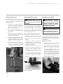
8. Make sure your extension cord is
in good condition. When using an
extension cord, be sure to use one
heavy enough to carry the current
your trimmer/edger will draw. An
undersized extension cord will cause
a drop in line voltage resulting in loss
of power and overheating.
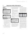
e table below shows the correct
size extension cord to use depend-
ing on cord length and nameplate
ampere rating. If in doubt, use the
next larger gauge cord. e smaller
the gauge number, the larger the cord.
To reduce the risk of disconnection
of trimmer/edger from the extension
cord during operation, use the cord
hitch described in this manual.
25 feet
50 feet
100 feet
150 feet
18 AWG
16 AWG
16 AWG
14 AWG
READ ALL INSTRUCTIONS BEFORE
OPERATING TRIMMER/EDGER.

118035
10.
Provide Ground Fault Circuit Inter-
rupter (GFCI) protection on the
circuit or outlet to be used for trim-
mer/edger. You may use receptacles
with built-in GFCI protection for
this safety measure.
1. Maintain trimmer/edger with care.
•
Inspect trimmer/edger cord pe-
riodically, and if damaged, have
it repaired by a qualified service
facility.
• Inspect extension cords periodically
and replace if damaged.
• If trimmer/edger is not working
properly, has been dropped, dam-
aged, left outdoors, or dropped into
water, have it repaired by a qualified
service center.
• Keep handles dry, clean, and free
from oil and grease.
• Keep guards in place and in work-
ing order.
2. Check damaged parts.
• If a part is damaged, carefully check
the damaged part before using the
trimmer/edger. Make sure the part
will operate properly and perform
its intended function.
• Check for alignment of moving
parts, binding of moving parts,
breakage of parts, mounting, and
any other condition that may affect
its operation.
• A guard or other part that is dam-
aged should be properly repaired or
replaced by a qualified service center
unless indicated elsewhere in this
manual.
• Use only geniune Remington®
replacement parts and accessories.
ese are available from your local
dealer. Use of any non-Reming-
ton® parts or accessories could lead
to injury to the user, damage to the
unit, and void you warranty.
3. Servicing of Double-Insulated
Tools:
• In a double-insulated tool, two
systems of insulation are provided
instead of grounding. No ground-
ing means is provided on a double-
insulated tool, nor should a means
for grounding be added to the tool.
Servicing a double-insulated tool
requires extreme care and knowl-
edge of the system, and should
be done only by qualified service
personnel. Replacement parts for
a double-insulated tool must be
identical to the parts they replace.
4. Store idle trimmer/edger indoors.
When not in use, store trimmer/edger
and extension cord indoors in a dry
location. Store trimmer/edger above
the reach of children or in a locked
area out of the reach of children.
is manual is your guide to safe and proper
operation of the trimmer/edger.
SAVE THESE
INSTRUCTIONS.
1. Stay alert. Watch what you are doing.
Use common sense.
2.
Be aware of extension cord while operat-
ing trimmer/edger. Be careful not to trip
over extension cord.
3. Avoid unintentional starting. Do
not carry plugged-in trimmer/edger
with finger on switch. Be sure switch
is OFF when plugging in trimmer/
edger.
4. Do not overreach. Keep proper foot-
ing and balance at all times when
operating trimmer/edger.
5. Disconnect the trimmer/edger from
the power supply
• when not in use
• before servicing
6. Do not force trimmer/edger. It will do
the job better and with less likelihood
of a risk of injury at the rate for which
it was designed.
7. Do not abuse power cord. Never pull
or carry trimmer/edger by power cord.
Never yank cord to disconnect from
receptacle. Keep power cord from
heat, oil, and sharp edges.
8. Keep hands and feet away from cut-
ting area.

118035
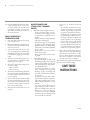
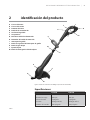
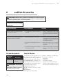
Input
No Load Speed
Cutting Width
Net Weight
Line Diameter
120V, 3.8A
1000 spm
12 inches (45.7cm)
6.35 lbs. (2.88 Kg)
0.065 inch
120V, 4.5A
1000 spm
14 inches (55.9cm)
6.35 lbs. (2.88 Kg)
0.065 inch
Figure 2-1: Remington® electric trimmer/edger (model ST3812B shown)

118035
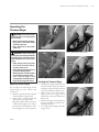
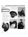
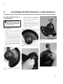
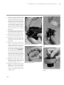
Figure 3-3: Attaching mounting screw
Figure 3-1: Placing cutting guard over cutting head
Figure 3-2: Rotating cutting guard into place
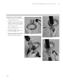
Figure 3-4: Placing edging wheel over screw holes
Figure 3-5: Attaching edging wheel
1. Remove three mounting screws taped
to underside of cutting guard.
2. Align key tabs on inside of cutting
guard hole with cutouts on motor
housing and slide cutting guard over
cutting head (see Figure 3-1). Slip
cutting guard past the tabs.
3. Rotate guard 90° until it stops (see
Figure 3-2).
4. Insert one mounting screw into center
screw hole at top of cutting guard (see
Figure 3-3). Tighten screw firmly.
5. Place edging wheel over remaining
two screw holes at top of cutting
guard (see Figure 3-4). Attach edging
wheel using two mounting screws.

118035
Figure 3-6: Removing knob and bolt from handle
Figure 3-7: Placing handle onto shaft
Figure 3-8: Inserting bolt into handle
Figure 3-9: Screwing knob onto bolt
1. Remove the knob and bolt from front
handle (see Figure 3-6).
2. Place the handle on the trimmer/
edger shaft between the rear handle
and the telescope release button. Snap
handle onto shaft (see Figure 3-7).
3. Insert bolt back into the front handle
(see Figure 3-8).
4. Loosely screw knob onto bolt (see
Figure 3-9).
5. Adjust handle to the most comfort-
able position and tighten the knob
firmly. Do not overtighten the knob.

118035
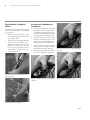
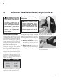
Figure 4-2: Plugging extension cord into inlet plug,
Model ST3812B
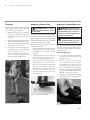
Safety Warnings
Use proper extension cord with this tool.
Use only a polarized (i.e., one blade is
wider than the other), UL listed exten-
sion cord marked for outdoor use. e
cord must be marked with suffix W or
W-A following the cord type designation.
Example: SJTW-A or SJTW.
Use proper sized cord with this tool. Cord
must be heavy enough to carry current
needed. An undersized cord will cause volt-
age drop at trimmer/edger. e trimmer/
edger will lose power and overheat. Follow
cord size requirements listed below.
Inspect cord often. Replace if damaged.
e trimmer/edger has a built-in extension
cord retainer. is cord hitch prevents ac-
cidental disconnection of the power cord
during use. e cord hitch is molded into
the rear handle.
1a. Model ST4514B: Plug power cord
into extension cord (see Figure 4-1).
1b.
Model ST3812B: Plug extension cord
into inlet plug of tool (see Figure 4-2).
2. Create a loop in the extension cord
and insert through the bottom of the
tool housing (see Figure 4-3).
3. Pull the loop tight around the molded
cord hitch (see Figure 4-4).
Note: For Model ST4514B, an optional
method of retaining the extension cord
is shown in Figure 4-5. Use this method
with larger-gauge cords that may not fit
into the extension cord retainer.
Figure 4-1: Plugging extension cord into power cord,
Model ST4514B
Figure 4-4: Pull extension cord loop tight around molded
cord hitch
Figure 4-5: Optional method of retaining extension cord
Figure 4-3: Inserting extension cord loop through bottom
of handle
25 feet
50 feet
100 feet
150 feet
18 AWG
16 AWG
16 AWG
14 AWG

118035
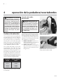
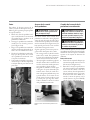
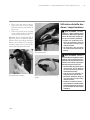
Figure 4-8: Holding trimmer/edger rear handle
Figure 4-9: Pressing trigger switch safety button
Figure 4-10: Squeezing trigger switch
1. Hold trimmer/edger using both front
and rear handles. Keep your thumb
and fingers off the button and switch
on the rear handle (see Figure 4-8).
2. When ready to start the trimmer/
edger, press in the trigger switch
safety button with your thumb (see
Figure 4-9).
3. Squeeze the trigger switch with your
fingers (see Figure 4-10). e trim-
mer/edger will start.
4. To stop the trimmer/edger, release the
trigger switch.
You can adjust the shaft length of this
trimmer/edger for your comfort and
convenience.
1. Slide telescope release button upward
toward handle (see Figure 4-6).
2. Adjust shaft to desired length and
release button (see Figure 4-7).
Note: e inside shaft has notches in
it. Adjust shaft length to one of these
preset positions. You will hear a “click”
when engaged into a notch properly.
Figure 4-6: Sliding telescoping release button upward
Figure 4-7: Adjusting shaft length
Trigger Switch
Safety Button

118035
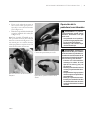
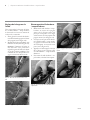
Figure 4-11: Holding trimmer/edger
Figure 4-12: Advancing trimmer/edger line
To reduce excessive line wear and improve
trimming performance, follow the steps
below to trim grass and weeds.
1. Remove any string, wire, or other ma-
terials that could become entangled
in the trimmer/edger from the trim-
ming area.
2. Hold trimmer/edger using both front
and rear handles (see Figure 4-11).
3. Slowly sweep the trimmer/edger from
side to side or front to back.
4. Do not force the trimmer/edger. Al-
low only the tip of the trimmer/edger
line to cut the grass or weeds.
5. If grass or weeds are tall, cut them in
several increments, starting from the
top and working to the bottom.
To advance new trimmer/edger line, tap the
line advance button on the ground while the
trimmer/edger is running (see Figure 4-12).
e blade attached to the cutting guard will
cut the line to the proper length.
Follow the precautions below to ensure
top line performance.
• Do not hold the line advance button
on the ground. is will allow trim-
mer/edger line to constantly feed off
the spool.
• Tap the line advance button only once
to advance line. If more line is needed,
wait a few seconds and tap again.
• Be sure to advance the line as it wears
down. If you wait too long to advance
new line, the existing line will wear
down too short and can retract into
the spool. If this happens, remove the
spool and reroute the line out of the
spool. Reinstall the spool to the trim-
mer/edger head.
For replacement line, use a nylon monofila-
ment line of 0.065 inch in diameter. You
can purchase replacement line at most lawn
and garden stores.
1. Press in the two locking tabs holding
the spool cover to the spool housing
(see Figure 4-13).
2.
Remove the spool cover and spool
from spool housing (see Figure
4-14). Note: If spool spring comes off
of spool housing, replace spring by
placing the smaller end of spring into
center of spool housing. Note: If install-
ing replacement spool and line (P/N
RS65B), skip to step 13, page 10.
3. Clean grass and other debris from the
spool and spool housing using a brush
(see Figure 4-15).
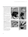
Figure 4-13: Unlocking spool cover
Line
Advance
Button

118035
4. Remove the line retaining ring from
the spool (see Figure 4-16).
5. Measure out 30 feet of replacement
line.
6. Push one end of the new line through
the left line mounting hole on the
spool (see Figure 4-17).
7. Feed 15 feet of the line through this
hole. Feed the other 15 feet of line
through the right line mounting hole
(see Figure 4-18). Pull the line tight
(see Figure 4-19).
Figure 4-14: Removing spool cover and spool
Figure 4-15: Cleaning spool
Figure 4-16: Removing line retaining ring
Figure 4-17: Inserting line in left hole
Figure 4-18: Inserting line in right hole
Figure 4-19: Pulling line tight
Line Retaining
Ring
Direction of
Line Feed
Direction of
Line Feed
Direction of
Line Feed

118035
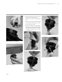
8. Lay the line from the left mounting
hole into the upper spool section. Lay
the line from the right mounting hole
across the other line. Insert this line
into the retaining slot between the
upper and lower spool section, then
lay the line into the lower spool sec-
tion. See Figure 4-20 for proper line
placement.
9. Place the line from the upper spool
section through the line retaining ring
(see Figure 4-21).
10. Place the line retaining ring back on
the spool (see Figure 4-22).
11. Position each line section in the slots
on either side of the retaining ring
(see Figure 4-23).
12. Hold the retaining ring in place
and make sure the line remains in
the retaining ring slots. Rotate the
spool while holding the retain-
ing ring in place. e line will roll
onto the spool (see Figure 4-24).
IMPORTANT: Make sure to rotate the
spool so the line winds onto spool in
the direction indicated on the spool
top. Wind line until four inches of
line remains outside the spool.
13. Replace spool onto spool spring and
press spool down. Lay exposed trim-
mer/edger line into slots on spool
housing (see Figure 4-25).
14. Align tabs on spool cover with slots
in spool housing. Replace spool cover
onto spool housing and snap into
place (see Figure 4-26).
Figure 4-20: Arranging line into spool
Figure 4-21: Placing upper spool line into retaining ring
Figure 4-23: Positioning line in retaining ring slots
Figure 4-22: Placing retaining ring onto spool
Retaining
Slot
Lines Through
Slots in
Retaining Ring

118035
Figure 4-24: Winding line onto spool
Figure 4-25: Replacing spool into spool housing
Figure 4-26: Replacing spool cover onto spool housing

118035
is tool easily converts to an trimmer/
edger. Follow the steps below.
1. Slide telescope release button upward
toward handle (see Figure 4-27).
2. Adjust shaft to desired length and
release button (see Figure 4-28).
Note: Make sure inner shaft locks
into one of the preset notches before
operating.
3. Press the shaft rotation button lo-
cated on the rear handle (see Figure
4-29).
4. Holding the rear handle in place,
grasp the front handle and rotate
the shaft and power head 180° to the
edging position (see Figure 4-30).
5. Release the shaft rotation button.
6. Loosen knob on front handle. Rotate
handle 180° and tighten knob.
Figure 4-29: Pressing shaft rotation release button
Figure 4-30: Rotating shaft and power head
1. Make sure trimmer/edger line is
advanced to full cutting length.
2. Roll the trimmer/edger using the
edging wheel attached to the cutting
guard (see Figure 4-31).
3. Start the trimmer/edger and trim
along edging lines. Be sure to keep
the cutting lines vertical.
Figure 4-31: Edging
Figure 4-27: Sliding telescoping release button upward
Figure 4-28: Adjusting shaft length

118035
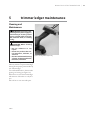
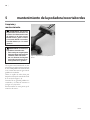
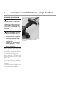
Use a soft cloth dampened with a mild soap
and water mixture to wipe trimmer/edger
housing. Do not spray or pour water directly
onto trimmer/edger.
Use a stiff bristled brush to clean air intake
openings on housing (see Figure 5-1).
When not in use, store the trimmer/edger
and extension cord indoors in a dry loca-
tion.
is tool has no user serviceable parts.
Figure 5-1: Cleaning trimmer/edger housing

118035
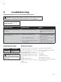
Motor does not run when you turn trig-
ger switch on
1. Extension cord connection is loose 1. Check cord connection at electri-
cal outlet and at rear of trimmer/
edger
Line does not feed when you tap the
line advance button
1. All line has been used on spool
2. Line has retracted into spool
3. Line is caught or tangled on spool
and will not feed
1. Install new line on spool, following
steps under Replacing Trimmer/
Edger Line, page 8
2. Remove spool and pull line out,
then replace spool
3. Remove spool, loosen and un-
tangle line, then replace spool
Note: For additional help, visit our
technical service web site at
You may have further questions about
assembling, operating, or maintain-
ing this trimmer/edger. If so, you can
visit our Technical Service web site at
www.desatech.com or contact our
Technical Service Department at 1-800-
858-8501 (English only). You may also
write to:
DESA Specialty Products™
ATTN: Technical Service Specialty
Products
P.O. Box 90004
Bowling Green, KY 42102-9004
When contacting DESA Specialty Prod-
ucts™, have ready
• Your Name
• Your Address
• Your Phone Number
• Model Number of Product
• Date of Purchase (include copy of receipt
for written requests)
RS65B Replacement Spool
with Line

118035
REMINGTON® ELECTRIC TRIMMER/EDGER LIMITED WARRANTY
Always specify model number when contacting the factory.
We reserve the right to amend these specifications at any time without notice. e only warranty applicable is our standard
written warranty. We make no other warranty, expressed or implied.
DESA Specialty Products™ warrants this Electric Trimmer/Edger and any parts thereof, to be free from defects in material
and workmanship for two years (90 days for reconditioned unit) from the date of first purchase from an authorized dealer,
provided that the product has been properly maintained and operated in accordance with all applicable instructions. is
warranty is extended only to the original retail purchaser. e bill of sales or proof of purchase must be presented at the time
a claim is made under this warranty.
is warranty does not cover commercial, industrial, or rental usage, nor does it apply to parts that are not in original condition
because of normal wear and tear, or parts that fail or become damaged as a result of misuse, accident, lack of proper mainte-
nance, tampering, or alteration. Travel, handling, transportation, and incidental costs associated with warranty repairs are not
reimbursable under this warranty and are the responsibility of the owner.
To the full extent allowed by the law of the jurisdiction that governs the sale of the product, this express warranty excludes
any and all other expressed warranties and limits the duration of any and all implied warranties, including warranties of mer-
chantability and fitness for a particular purpose to two years form the date of first purchase, and DESA Specialty Products’™
liability is hereby limited to the purchase price of the product and DESA Specialty Products™ shall not be liable for any other
damages whatsoever including indirect, incidental, or consequential damages.
Some states do not allow limitation of how long an implied warranty lasts or an exclusion or limitation of incidental or con-
sequential damages, so the above limitation of damages may not apply to you.
is warranty provides the original purchaser with specific rights. For information regarding those rights, please consult the
applicable state laws.
P.O. Box 90004
Bowling Green, KY 42102-9004
www.desatech.com

118035
La page est en cours de chargement...
La page est en cours de chargement...
La page est en cours de chargement...
La page est en cours de chargement...
La page est en cours de chargement...
La page est en cours de chargement...
La page est en cours de chargement...
La page est en cours de chargement...
La page est en cours de chargement...
La page est en cours de chargement...
La page est en cours de chargement...
La page est en cours de chargement...
La page est en cours de chargement...
La page est en cours de chargement...
La page est en cours de chargement...
La page est en cours de chargement...
La page est en cours de chargement...
La page est en cours de chargement...
La page est en cours de chargement...
La page est en cours de chargement...
La page est en cours de chargement...
La page est en cours de chargement...
La page est en cours de chargement...
La page est en cours de chargement...
La page est en cours de chargement...
La page est en cours de chargement...
La page est en cours de chargement...
La page est en cours de chargement...
La page est en cours de chargement...
La page est en cours de chargement...
La page est en cours de chargement...
La page est en cours de chargement...
La page est en cours de chargement...
La page est en cours de chargement...
La page est en cours de chargement...
La page est en cours de chargement...
La page est en cours de chargement...
La page est en cours de chargement...
La page est en cours de chargement...
La page est en cours de chargement...
La page est en cours de chargement...
La page est en cours de chargement...
La page est en cours de chargement...
La page est en cours de chargement...
-
 1
1
-
 2
2
-
 3
3
-
 4
4
-
 5
5
-
 6
6
-
 7
7
-
 8
8
-
 9
9
-
 10
10
-
 11
11
-
 12
12
-
 13
13
-
 14
14
-
 15
15
-
 16
16
-
 17
17
-
 18
18
-
 19
19
-
 20
20
-
 21
21
-
 22
22
-
 23
23
-
 24
24
-
 25
25
-
 26
26
-
 27
27
-
 28
28
-
 29
29
-
 30
30
-
 31
31
-
 32
32
-
 33
33
-
 34
34
-
 35
35
-
 36
36
-
 37
37
-
 38
38
-
 39
39
-
 40
40
-
 41
41
-
 42
42
-
 43
43
-
 44
44
-
 45
45
-
 46
46
-
 47
47
-
 48
48
-
 49
49
-
 50
50
-
 51
51
-
 52
52
-
 53
53
-
 54
54
-
 55
55
-
 56
56
-
 57
57
-
 58
58
-
 59
59
-
 60
60
-
 61
61
-
 62
62
-
 63
63
-
 64
64


Remington ST3812B, ST4514B Manuel utilisateur
- Catégorie
- Coupe-herbe
- Taper
- Manuel utilisateur
- Ce manuel convient également à

