Bosch Power Tools 53514 Manuel utilisateur
- Catégorie
- Raboteuses électriques
- Taper
- Manuel utilisateur
Ce manuel convient également à

Operating/Safety Instructions
Consignes de fonctionnement/sécurité
Instrucciones de funcionamiento
y seguridad
53514
53518
IMPORTANT: IMPORTANT : IMPORTANTE:
Read Before Using Lire avant usage Leer antes de usar
Consumer Information
Renseignement des consommateurs
Información para el consumidor
Toll Free Number: Appel gratuit : Número de teléfono gratuito:
1-877-BOSCH99 (1-877-267-2499) http://www.boschtools.com
For English Parlez-vous français? ¿Habla español?
See page 2 Voir page 14 Ver página 26
BM 2610917139 6/02 7/10/02 10:50 AM Page 1

-2-
Read and understand all instructions. Failure to follow all instructions
listed below, may result in electric shock, fire and/or serious personal injury.
SAVE THESE INSTRUCTIONS
Work Area
Keep your work area clean and well lit.
Cluttered benches and dark areas invite
accidents.
Do not operate power tools in explosive
atmospheres, such as in the presence of
flammable liquids, gases, or dust. Power
tools create sparks which may ignite the
dust or fumes.
Keep by-standers, children, and visitors
away while operating a power tool.
Distractions can cause you to lose control.
Electrical Safety
Do not abuse the cord. Never use the
cord to carry the tool. Keep cord away
from heat, oil, sharp edges, or moving
parts. Replace damaged cords
immediately. Damaged cords may create a
fire.
A battery operated tool with integral
batteries or a separate battery pack must
be recharged only with the specified
charger for the battery. A charger that may
be suitable for one type of battery may
create a risk of fire when used with another
battery.
Use battery operated tool only with
specifically designated battery pack. Use
of any other batteries may create a risk of
fire.
Personal Safety
Stay alert, watch what you are doing, and
use common sense when operating a
power tool. Do not use tool while tired or
under the influence of drugs, alcohol, or
medication. A moment of inattention while
operating power tools may result in serious
personal injury.
Dress properly. Do not wear loose
clothing or jewelry. Contain long hair.
Keep your hair, clothing, and gloves away
from moving parts. Loose clothes, jewelry,
or long hair can be caught in moving parts.
Avoid accidental starting. Be sure switch
is in the locked or off position before
inserting battery pack. Carrying tools with
your finger on the switch or inserting the
battery pack into a tool with the switch on
invites accidents.
Remove adjusting keys or wrenches
before turning the tool on. A wrench or a
key that is left attached to a rotating part of
the tool may result in personal injury.
Do not overreach. Keep proper footing
and balance at all times. Proper footing
and balance enable better control of the tool
in unexpected situations.
Use safety equipment. Always wear eye
protection. Dust mask, non-skid safety
shoes, hard hat, or hearing protection must
be used for appropriate conditions.
Tool Use and Care
Use clamps or other practical way to
secure and support the workpiece to a
stable platform. Holding the work by hand
or against your body is unstable and may
lead to loss of control.
Do not force tool. Use the correct tool for
your application. The correct tool will do
the job better and safer at the rate for which
it is designed.
Do not use tool if switch does not turn it
on or off. A tool that cannot be controlled
with the switch is dangerous and must be
repaired.
Disconnect battery pack from tool or
place the switch in the locked or off
position before making any adjustments,
changing accessories, or storing the tool.
Such preventive safety measures reduce the
risk of starting the tool accidentally.
Store idle tools out of reach of children
and other untrained persons. Tools are
dangerous in the hands of untrained users.
When battery pack is not in use, keep it
away from other metal objects like: paper
!
WARNING
General Safety Rules
For All Battery Operated Tools
BM 2610917139 6/02 7/10/02 10:50 AM Page 2

-3-
Safety Rules for Cordless Planers
Secure the material being planed. Never
hold it in your hand or across legs. Small
workpiece must be adequately secured so
that the rotating planer blades will not pick it
up during forward motion of the planer.
Unstable support can cause the blades to
bind causing loss of control and injury.
Always start the plane before blade is in
contact with the workpiece and allow the
blade to come to full speed. Tool can
vibrate or chatter if blade speed is too slow
at beginning of cut and possibly kickback.
Check the workpiece for nails, if there are
nails, either remove or set them well
below intended finished surface. If the
planer blades strike objects like nails it may
cause the tool to kickback and serious
personal injury may result.
Disconnect battery pack from tool or
place the switch in the locked or off
position before making any assembly,
adjustments or changing accessories.
Such preventive safety measures reduce the
risk of starting the tool accidentally.
After changing blades, rotate the blade
cylinder (cutter drum) to make sure
blades are not hitting any part of the
blade head housing and the blade locking
screws are tight. Spinning blades could
strike tool housing and damage tool as well
as possible injury.
Always hold the tool firmly with both
hands for maximum control.
Never pull the plane backward over the
workpiece. Loss of control may occur.
Do not put fingers or any objects into the
chip ejector or clean out chips while tool
is running. Contact with blade drum will
cause injury.
Disconnect battery pack from tool if it
becomes necessary to remove chips. The
blades are hidden from view and you may
be cut if blade is contacted.
Never place the plane down until the
blade is completely at rest. Surface
contact with coasting blade drum may
cause the plane to walk out of control.
Some dust created by
power sanding, sawing,
grinding, drilling, and other construction
activities contains chemicals known to
cause cancer, birth defects or other
reproductive harm. Some examples of
these chemicals are:
• Lead from lead-based paints,
• Crystalline silica from bricks and cement
and other masonry products, and
• Arsenic and chromium from chemically-
treated lumber.
Your risk from these exposures varies,
depending on how often you do this type of
work. To reduce your exposure to these
chemicals: work in a well ventilated area,
and work with approved safety equipment,
such as those dust masks that are specially
designed to filter out microscopic particles.
clips, coins, keys, nails, screws, or other
small metal objects that can make a
connection from one terminal to another.
Shorting the battery terminals together may
cause sparks, burns, or a fire.
Maintain tools with care. Keep cutting
tools sharp and clean. Properly maintained
tools with sharp cutting edge are less likely
to bind and are easier to control.
Check for misalignment or binding of
moving parts, breakage of parts, and any
other condition that may affect the tool's
operation. If damaged, have the tool
serviced before using. Many accidents are
caused by poorly maintained tools.
Use only accessories that are recom-
mended by the manufacturer for your
model. Accessories that may be suitable for
one tool may create a risk of injury when
used on another tool.
Service
Tool service must be performed only by
qualified repair personnel. Service or
maintenance performed by unqualified
personnel may result in a risk of injury.
When servicing a tool, use only identical
replacement parts. Follow instructions in
the Maintenance section of this manual.
Use of unauthorized parts or failure to follow
Maintenance Instructions may create a risk
of shock or injury.
!
WARNING
BM 2610917139 6/02 7/10/02 10:50 AM Page 3

Before using battery charger, read all
instructions and cautionary markings on
(1) battery charger, (2) battery pack, and
(3) product using battery.
Use only the charger which accompanied
your product or direct replacement as
listed in the catalog or this manual. Do not
substitute any other charger. Use only Bosch
approved chargers with your product. See
Functional Description and Specifications.
Do not disassemble charger or operate
the charger if it has received a sharp blow,
been dropped or otherwise damaged in
any way. Replace damaged cord or plugs
immediately. Incorrect reassembly or
damage may result in electric shock or fire.
Do not recharge battery in damp or wet
environment. Do not expose charger to
rain or snow. If battery case is cracked or
otherwise damaged, do not insert into
charger. Battery short or fire may result.
Charge only Bosch approved rechargeable
batteries. See Functional Description and
Specifications. Other types of batteries may
burst causing personal injury and damage.
Charge battery pack in temperatures
above +40 degrees F (4 degrees C) and
below +105 degrees F (41 degrees C).
Store tool and battery pack in locations
where temperatures will not exceed 120
degrees F (49 degrees C). This is important
to prevent serious damage to the battery
cells.
Battery leakage may occur under extreme
usage or temperature conditions. Avoid
contact with skin and eyes. The battery
liquid is caustic and could cause chemical
burns to tissues. If liquid comes in contact
with skin, wash quickly with soap and water,
then with lemon juice or vinegar. If the liquid
contacts your eyes, flush them with water for
a minimum of 10 minutes and seek medical
attention.
Place charger on flat non-flammable
surfaces and away from flammable
materials when re-charging battery pack.
The charger and battery pack heat during
charging. Carpeting and other heat
insulating surfaces block proper air
circulation which may cause overheating of
the charger and battery pack. If smoke or
melting of the case are observed unplug the
charger immediately and do not use the
battery pack or charger.
Use of an attachment not recom-
mended or sold by Bosch may result in a
risk of fire, electric shock or injury to
persons.
-4-
Battery/Charger
Battery Care
When batteries are not in
tool or charger, keep
them away from metal objects. For
example, to protect terminals from shorting
DO NOT place batteries in a tool box or
pocket with nails, screws, keys, etc. Fire or
injury may result.
To prevent fire or injury
when batteries are not in
tool or charger, always place protective
cap onto end of battery pack. Protective
cap, guards against terminal shorting.
DO NOT PUT BATTERIES INTO FIRE OR
EXPOSE TO HIGH HEAT. They may
explode.
!
WARNING
!
WARNING
BM 2610917139 6/02 7/10/02 10:50 AM Page 4

Do not attempt to disas-
semble the battery or
remove any component projecting from
the battery terminals. Fire or injury may
result. Prior to disposal, protect exposed
terminals with heavy insulating tape to
prevent shorting.
NICKEL-CADMIUM BATTERIES
If equipped with a nickel-cadmium battery,
the battery must be collected, recycled or
disposed of in an environmentally sound
manner.
“The EPA certified RBRC
Battery Recycling Seal on the
nickel-cadmium (Ni-Cd)
battery indicates S-B Power
Tool Company is voluntarily
participating in an industry
program to collect and recycle these
batteries at the end of their useful life, when
taken out of service in the United States or
Canada. The RBRC program provides a
convenient alterative to placing used Ni-Cd
batteries into the trash or the municipal
waste stream, which may be illegal in your
area.
Please call 1-800-8-BATTERY for information
on Ni-Cd battery recycling and disposal
bans/restrictions in your area, or return your
batteries to a Skil/Bosch/Dremel Service
Center for recycling. S-B Power Tool
Company’s involvement in this program is
part of our commitment to preserving our
environment and conserving our natural
resources.”
NICKEL-METAL HYDRIDE BATTERIES
If equipped with a nickel-metal hydride
battery, the battery can be disposed of in a
municipal solid waste stream.
-5-
!
WARNING
Battery Disposal
BM 2610917139 6/02 7/10/02 10:50 AM Page 5

-6-
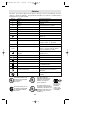
IMPORTANT: Some of the following symbols may be used on your tool. Please study them
and learn their meaning. Proper interpretation of these symbols will allow you to operate the
tool better and safer.
Symbol Name Designation/Explanation
V Volts Voltage (potential)
A Amperes Current
Hz Hertz Frequency (cycles per second)
W Watt Power
kg Kilograms Weight
min Minutes Time
s Seconds Time
Diameter Size of drill bits, grinding wheels, etc.
n
0
No load speed Rotational speed, at no load
.../min Revolutions or reciprocation per minute Revolutions, strokes, surface speed,
orbits etc. per minute
0 Off position Zero speed, zero torque...
1, 2, 3, ... Selector settings Speed, torque or position settings.
I, II, III, Higher number means greater speed
Infinitely variable selector with off Speed is increasing from 0 setting
Arrow Action in the direction of arrow
Alternating current Type or a characteristic of current
Direct current Type or a characteristic of current
Alternating or direct current Type or a characteristic of current
Class II construction Designates Double Insulated
Construction tools.
Earthing terminal Grounding terminal
Warning symbol Alerts user to warning messages
Ni-Cad RBRC seal Designates Ni-Cad battery recycling
program
Symbols
0
This symbol designates
that this tool is listed by
Underwriters Laboratories.
This symbol designates
that this tool is listed by
the Canadian Standards
Association.
This symbol designates
that this tool is listed to
Canadian Standards by
Underwriters Laboratories.
This symbol
designates
that
this tool
complies
to NOM
Mexican
Standards.
This symbol designates
that this tool is listed by
Underwriters Laboratories,
and listed to Canadian
Standards by Underwriters
Laboratories.
BM 2610917139 6/02 7/10/02 10:50 AM Page 6

-7-
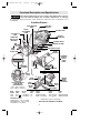
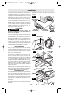
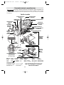
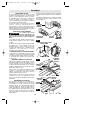
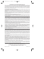
Functional Description and Specifications
Disconnect battery pack from tool or place the switch in the locked or
off position before making any assembly, adjustments or changing
accessories. Such preventive safety measures reduce the risk of starting the tool
accidentally.
!
WARNING
Cordless Planers
WING
KNOB
RABBETING
DEPTH STOP
(OPTIONAL)
DEPTH
ADJUSTMENT
KNOB
CHIP EXHAUST
PORT
CHIP EXHAUST PORT
DEPTH
SCALE
PORT SELECTOR
LEVER
TRIGGER SWITCH
“LOCK-OFF”
BUTTON
FRONT SHOE
PIVOT
FENCE
ROUND
KNOB
GUIDE
BRACKET
WING KNOB
WING KNOB
FENCE
SCREW
DRIVE BELT COVER
CHAMFER
V-GROOVE
GUIDE
BRACKET
WIDTH
SCALE
DELUXE
ANGLE
FENCE
(OPTIONAL)
WING
KNOB
STANDARD
PARALLEL
WIDTH
GUIDE
FENCE
FIG. 1
THE CUTTING DEPTH
CHOICES ARE
APPROXIMATELY
1/16", 3/64", 1mm (•),
1/32", 1/64", & 1/128" (•)
BATTERY
RELEASE TABS
BATTERY PACK
SCREW
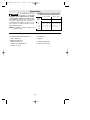
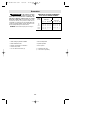
Maximum Capacities
Planing depth 0 - 1/16" (0 - 1.6mm)
Rabbeting depth 0 - 5/16" (0 - 8mm)
Cutting width 3-1/4" (82mm)
BC006 charger requires 12 V DC input
NOTE: ONLY USE CHARGERS LISTED ABOVE
Model Voltage No load Charge Charger Voltage Battery
number rating speed time number rating pack
53514 14.4 V n
0
13,000/min 1 hr. BC001-6 & BC016 120 V 60 Hz BAT040 & BAT038
53518 18 V n
0
13,000/min 1 hr. BC003, 4, 6, & BC016 120 V 60 Hz BAT026 & BAT025
BM 2610917139 6/02 7/10/02 10:50 AM Page 7

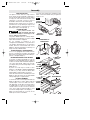
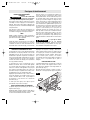
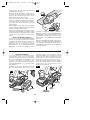
CHIP EXTRACTION
The planer comes with two chip exhaust
ports, which may be used with a chip bag or
a shop vacuum and vacuum connector (Fig.2)
to keep your work environment cleaner. The
chip bag or vacuum connector may be
attached to either end of the exhaust port.
Moving the port selector lever to position 1
(towards front of tool) discharges chips to the
left, while position 2 (towards rear of tool)
discharges chips to the right (Fig. 1)
PLANER BLADES
The planer blades are
sharp and fragile and must
be handled carefully to avoid injury to the
user or damage to the blades.
The planer blades have two cutting edges,
and may be reversed when one of the cutting
edges becomes dull or chipped.
Do not attempt to sharpen or use
resharpened used blades of any kind. Use
only blades designated for use with this
model, because other blades will cause
vibration, decrease perfomance and may not
clamp securely in blade holder.
BLADE WRENCH & STORAGE AREA
Your tool is equipped with a blade wrench
that is conveniently located in the handle
base where it is always handy and unlikely to
get lost or misplaced (Fig. 3).
REVERSING OR REPLACING BLADES
To reverse or replace the blade, loosen the
clamping screws with blade wrench. With the
screws loosened, slide the blade lengthwise
out of the cutter drum, taking care to keep
your fingers away from the sharp edges of the
blade (Fig. 4).
A piece of wood may be used for this
purpose. If the blade is gummed and difficult
to remove, you may clean the blade with
mineral spirits, lacquer thinner or alcohol.
Clean all surfaces before reinstalling the new
blade, as this will ensure an accurate blade
setting and proper tool performance.
BLADE ALIGNMENT
To ensure an even cut, it is important that the
blade is adjusted so that it aligns with the
outside edge of the front and rear shoes.
This alignment can be done as follows: place
a straight edge or a piece of wood along the
outside surface of the front shoe and rear
shoe, then slide the planer blade to just
contact the straight edge or wood (Fig.5).
Make sure the blade sits correctly in the
holder groove of the cutter drum.
You may then tighten the clamping screws
which secure the blade and your planer is
ready for use.
-8-
Assembly
FIG. 2
FIG. 4
FIG. 3
FIG. 5
CHIP BAG
(OPTIONAL)
EXHAUST
PORTS
VACUUM
CONNECTOR
BLADE
CLAMPING
SCREW
CUTTER
DRUM
CLAMPING
SCREW
BLADE WRENCH
2.5 MM BLADE
WRENCH
CUTTER
DRUM
STRAIGHT
EDGE
!
WARNING
BLADE WRENCH &
STORAGE AREA
BM 2610917139 6/02 7/10/02 10:50 AM Page 8

-9-
Operating Instructions
TRIGGER "ON/OFF" SWITCH
Hold the tool with both
hands while starting the
tool, since torque from the motor can
cause the tool to twist.
To turn tool "ON", depress the "Lock-OFF"
button and squeeze the trigger switch. To
turn the tool "OFF", release the trigger
switch which is spring loaded and will return
to "OFF" position automatically.
To increase switch life, do not turn switch on
and off while tool and drum are held against
a workpiece.
BRAKE
When the trigger is released it activates the
electrical brake to stop the blade quickly. This
feature is especially useful when making
repetitive cuts.
PLANING ACTION
Check that the workpiece is held in place
securely on your work surface, and standing
comfortably, hold the planer firmly with both
hands. With the planer fully adjusted, place
the front shoe on the workpiece, (be certain
that the cutter drum is not in contact with
the work) and start the planer as described
earlier. With pressure on the front shoe, and
the fence against the side of the work (to
control the width or angle,) feed the planer
steadily until the rear shoe fully engages the
workpiece. Now gradually transfer pressure
to the rear shoe, and continue planing to the
end of the cut. Feed the planer at a uniform
and reasonable rate, which does not put
excessive strain on the motor or blades, (do
not pull the planer back over the surface
already cut.) Use progressive cuts until you
are near the desired depth, and then re-
adjust to a light cut for the final pass to
obtain a good surface finish.
The motor may stall if
improperly used or
overloaded. Reduce the pressure (feed
rate) or depth of cut to prevent possible
damage to the tool if the motor labors.
!
CAUTION
ADJUSTING DEPTH OF CUT
Proper cutting depth should be determined
according to the hardness, gumminess or
moisture content of the material being cut,
as well as the feed rate, and is largely a
matter of experience. Start with a light cut
and increase the depth setting if the plane
moves freely through the workpiece with no
excessive load on the motor. Do not change
depth of cut while planing.
The cutting depth is determined by the
difference in height between the adjustable
front shoe, and the fixed rear shoe of the
planer. As the front shoe is adjusted, it
retracts and exposes the blade, which can
then remove the desired amount from the
workpiece. The cutting depth is graduated
from 0 to 1/16 of an inch, and the "0"
indicates the blade is fully retracted.
Adjusting depth of cut: Rotate depth
adjustment knob until the indicator engages
the detent which indicates the desired
cutting depth on the depth scale (Fig. 1).
The planer may be set to cut any depth from
0 to 1/16 of an inch.
STANDARD PARALLEL WIDTH
GUIDE FENCE
The width guide fence can be used to cut
various desired widths (Fig. 1).
Installing the guide fence: Place the wing
knob through the appropriate hole in the
guide bracket and screw into the housing.
Securely tighten wing knob.
Setting the cutting width: Loosen wing knob
and slide the fence along the guide bracket
to the desired position. Securely tighten
wing knob. Be certain that the flat washer
(supplied) is fitted between the bottom of the
guide fence and wing knob or the guide
fence is likely to slip.
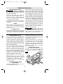
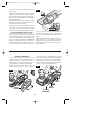
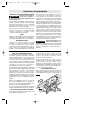
DELUXE ANGLE FENCE
The optional deluxe angle fence (Fig. 6) can
be used to cut various desired widths, with
the additional capability of guiding the
!
WARNING
82 mm
max
8 mm
max
FIG. 6
BM 2610917139 6/02 7/10/02 10:50 AM Page 9

-10-
planer on any angle up to 45 degrees, to
allow edge chamfering (Fig. 7).
Installing the angle fence: Place the wing
knob through the appropriate hole in the
guide bracket and screw into the housing.
Securely tighten wing knob (Fig. 1).
Setting the cutting width: Loosen wing knob
and using the width scale, slide the fence
along the guide bracket to the desired
position. Securely tighten wing knob (Fig. 1).
Setting the cutting angle: Loosen round
knobs and pivot the fence to the desired
position. Securely tighten round knobs (Fig. 1).
Note that the adjustable front shoe contains
a chamfer V-groove, which will follow the
corner of a workpiece to allow easier
handling when using the deluxe angle/width
fence (Fig. 7).
RABBETING DEPTH STOP
The optional rabbeting depth stop accessory
(Fig. 1) allows the user to set any rabbeting
depth from 0 to 5/16 inch. For best results, it
is important that the blade be properly
aligned (See "BLADE ALIGNMENT"). The
width of the rabbet is controlled by the width
fence. The maximum cutting width is 3-1/4",
and the final depth is achieved by repetitive
cutting until the rabbeting depth guide
contacts the workpiece. The maximum
rabbeting depth is 5/16"
Setting the rabbet depth: Loosen wing knob
and using the depth scale on the rabbeting
depth stop, set the desired rabbet depth.
Securely tighten wing knob.
FIG. 7
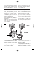
DRIVE BELT
The drive belt is a normal maintenance part
and should be inspected periodically for
wear. If the drive belt shows signs of drying
out, cracking or tearing, it should be
replaced. If the drive belt will not track
properly or comes off the pulleys, it should
be replaced.
Installing new drive belt: Loosen screws and
remove the drive belt cover (Fig. 8). Cut and
remove the worn drive belt. Before installing
the new drive belt, clean both pulleys
thoroughly. First place the new drive belt
onto the drive pulley then rotate clockwise
while pushing the belt onto the driven pulley.
Reinstall the drive belt cover and securely
tighten screws (Fig. 9).
FIG. 9
DRIVE
PULLEY
DRIVEN
PULLEY
DRIVE
BELT
DRIVE
BELT
COVER
SCREW
FIG. 8
BM 2610917139 6/02 7/10/02 10:50 AM Page 10

-11-
Release battery pack from tool by pressing
on both sides of the battery release tabs and
pull downwards. Before inserting battery
pack, remove protective cap from battery
pack. To insert battery, align battery and
slide battery pack into tool until it locks into
position. Do not force.
RELEASING AND INSERTING BATTERY PACK
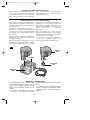
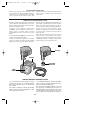
CHARGING BATTERY PACK (1 HOUR CHARGER)
Plug charger cord into your standard power
outlet. Before inserting battery pack, remove
protective cap, then insert battery pack into
charger (Fig. 10).
The charger’s green indicator will begin to
“BLINK”. This indicates that the battery is
receiving a fast charge. Fast-charging will
automatically stop when the battery pack is
fully charged.
When the indicator light stops “BLINKING”
(and becomes a steady green light) fast
charging is complete.
When you begin the charging process of the
battery pack, a steady green light could also
mean the battery pack is too hot or too cold.
The purpose of the light is to indicate that the
battery pack is fast-charging. It does not
indicate the exact point of full charge. The
light will stop blinking in less time if the
battery pack was not completely
discharged.
When the battery pack is fully charged,
unplug the charger (unless you're charging
another battery pack) and slip the battery
pack back into the tool handle.
To prevent fire or injury when batteries are
not in tool or charger, always place
protective cap onto end of battery pack.
INDICATOR
LIGHT
CHARGER
BATTERY
PACK
PROTECTIVE
CAP
1. The battery pack accepts only about 80%
of its maximum capacity with its first few
charge cycles. However, after the first few
charge cycles, the battery will charge to full
capacity.
2. The charger was designed to fast charge
the battery only when the battery
temperature is between 40˚F (4˚C) and 105˚F
(41˚C).
3. A substantial drop in operating time per
charge may mean that the battery pack is
nearing the end of its life and should be
replaced.
IMPORTANT CHARGING NOTES
FIG. 10
BM 2610917139 6/02 7/10/02 10:50 AM Page 11

Maintenance
Service
NO USER SERVICEABLE
PARTS INSIDE. Preventive
maintenance performed by unauthorized
personnel may result in misplacing of
internal wires and components which
could cause serious hazard. We recom-
mend that all tool service be performed by a
Bosch Factory Service Center or Authorized
Bosch Service Station. SERVICEMEN:
Disconnect tool and/or charger from power
source before servicing.
BATTERIES
Be alert for battery packs that are nearing
their end of life. Battery packs typically last
from 500 to 1000 charges. If you notice
decreased tool performance or significantly
shorter running time between charges then it
is time to replace the battery pack. Failure
to do so can cause the tool to operate
improperly or damage the charger.
Long term battery storage should be in
the discharged state. Battery packs last
longer and re-charge better when they are
stored discharged. Remember to fully re-
charge battery packs before using after
prolonged storage.
TOOL LUBRICATION
Your Bosch tool has been properly lubricated
and is ready for use. It is recommended that
tools with gears be regreased with a special
gear lubricant yearly.
D.C. MOTORS
The motor in your tool has been engineered
for many hours of dependable service. To
maintain peak efficiency of the motor, we
recommend it be examined every six
months. Only a genuine Bosch replacement
motor specially designed for your tool should
be used.
Cleaning
To avoid accidents, always
disconnect the tool and/or
charger from the power supply before
cleaning. The tool may be cleaned most
effectively with compressed dry air. Always
wear safety goggles when cleaning tools
with compressed air.
Ventilation openings and switch levers must
be kept clean and free of foreign matter. Do
not attempt to clean by inserting pointed
objects through opening.
Certain cleaning agents
and solvents damage
plastic parts. Some of these are: gasoline,
carbon tetrachloride, chlorinated cleaning
solvents, ammonia and household
detergents that contain ammonia.
!
WARNING
!
WARNING
!
CAUTION
-12-
4. If you anticipate long periods (i.e. a month
or more) of non-use of your tool, it is best to
run your tool down until it is fully discharged
before storing your battery pack. After a long
period of storage, the capacity at first
recharge will be lower. Normal capacity will be
restored in two or three charge/discharge
cycles. Remember to unplug charger during
storage period.
5. If battery does not charge properly:
a. Check for voltage at outlet by
plugging in some other electrical device.
b. Check to see if outlet is connected to
a light switch which turns power “off” when
lights are turned off.
c. Check battery pack terminals for dirt.
Clean with cotton swab and alcohol if
necessary.
d. If you still do not get proper charging,
take or send tool, battery pack and charger
to your local Bosch Service Center. See
“Tools, Electric” in the Yellow Pages for
names and addresses.
Note: Use of chargers or battery packs not
sold by Bosch may void the warranty.
BM 2610917139 6/02 7/10/02 10:50 AM Page 12

-13-
Accessories
If an extension cord is
necessary, a cord with
adequate size conductors that is capable
of carrying the current necessary for your
tool must be used. This will prevent
excessive voltage drop, loss of power or
overheating. Grounded tools must use 3-
wire extension cords that have 3-prong
plugs and receptacles
.
NOTE: The smaller the gauge number, the
heavier the cord.
RECOMMENDED SIZES OF EXTENSION CORDS
120 VOLT ALTERNATING CURRENT TOOLS
!
WARNING
Tool’s
Ampere
Rating
Cord Size in A.W.G.
Wire Sizes in mm
2
3-6
6-8
8-10
10-12
12-16
18 16 16 14 .75 .75 1.5 2.5
18 16 14 12 .75 1.0 2.5 4.0
18 16 14 12 .75 1.0 2.5 4.0
16 16 14 12 1.0 2.5 4.0 —
14 12 — — — — — —
25 50 100 150 15 30 60 120
Cord Length in Feet Cord Length in Meters
* Standard parallel width guide fence
** Deluxe angle fence
** Rabbeting depth stop
* Blade wrench 2.5mm
* Carbide reversible blades (2)
* Vacuum connector
** Vacuum hose
** Chip bag
(*= standard equipment)
(**= optional accessories)
BM 2610917139 6/02 7/10/02 10:50 AM Page 13

-14-
Consignes générales de sécurité
pour tous les outils à pile
Vous devez lire et comprendre toutes les instructions. Lenon-respect, même partiel,
des instructions ci-après entraîne un risque de choc életrique, d'incendie et/ou de
blessures graves.
CONSERVEZ CES INSTRUCTIONS
AVERTISSEMENT
!
Aire de travail
Veillez à ce que l'aire de travail soit propre et bien
éclairée. Le désordre et le manque de lumière
favorisent les accidents.
N'utilisez pas d'outils électriques dans une
atmosphère explosive, par exemple enprésence de
liquides, de gaz ou de poussières inflammables. Les
outils électriques créent des étincelles qui pourraient
enflammer les poussières ou les vapeurs.
Tenez à distance les curieux, les enfants et les
visiteurs pendant que vous travaillezavec un outil
électrique. Ils pourraient vous distraire et vous faire
faire une fausse manoeuvre.
Sécurité électrique
N'abusez pas du cordon. Ne transportez jamais
l'outil par le cordon. Tenez le cordon à l'écart de la
chaleur, de l'huile, des arêtes vives ou des pièces
mobiles. Remplacez les cordons endommagés
immédiatement. Les cordons endommagés peuvent
provoquer un incendie.
Un outil à pile avec piles incorporées ou bloc-pile
distinct doit être rechargé uniquement avec le
chargeur indiqué pour la pile. Un chargeur qui peut
être adéquat pour un type de pile peut créer un risque
d'incendie lorsqu'il est utilisé avec une autre pile.
Utiliser un outil à pile uniquement avec le bloc-pile
désigné spécifiquement. L'emploi de toute autre pile
peut créer un risque d'incendie.
Sécurité des personnes
Restez alerte, concentrez-vous sur votre travail et
faites preuve de jugement. N'utilisez pas un outil
électrique si vous êtes fatigué ou sous l'influence de
drogues, d'alcool ou de médicaments. Un instant
d'inattention suffit pour entraîner des blessures graves.
Habillez-vous convenablement. Ne portez ni
vêtements flottants ni bijoux. Confinez les cheveux
longs. N'approchez jamais les cheveux, les
vêtements ou les gants des pièces en mouvement.
Des vêtements flottants, des bijoux ou des cheveux
longs risquent d'être happés par des pièces en
mouvement. Gardez les poignées sèches, propres et
exemptes d'huile et de graisse.
Évitez la mise en marche accidentelle. Assurez-vous
que l'interrupteur est en position de blocage ou
d'arrêt avant d'insérer le bloc-pile. Il est dangereux
de transporter l'outil avec le doigt sur l'interrupteur ou
d'insérer le bloc-pile dans un outil alors que
l'interrupteur est en position de marche.
Enlevez les clés de réglage ou de serrage avant de
démarrer l'outil. Une clé laissée dans une pièce
tournante de l'outil peut provoquer des blessures.
Ne vous penchez pas trop en avant. Maintenez un bon
appui et restez en équilibre entout temps. Un bonne
stabilité vous permet de mieux réagir à une situation
inattendue.
Utilisez des accessoires de sécurité. Portez toujours
des lunettes ou une visière. Selon les conditions,
portez aussi un masque antipoussière, des bottes de
sécurité antidérapantes, un casque protecteur et/ou un
appareil antibruit.
Utilisation et entretien des outils
Immobilisez le matériau sur une surface stable au
moyen de brides ou de toute autre façon adéquate. Le
fait de tenir la pièce avec la main ou contre votre corps
offre une stabilité insuffisante et peut amener un
dérapage de l'outil.
Ne forcez pas l'outil. Utilisez l'outil approprié à la
tâche. L'outil correct fonctionne mieux et de façon plus
sécuritaire. Respectez aussi la vitesse de travail qui lui
est propre.
N'utilisez pas l'outil si l'interrupteur ne le met pas
en marche ou à l'arrêt. Un outil qui ne peut être
contrôlé par l'interrupteur est dangereux et doit être
réparé.
Débranchez le bloc-pile de l'outil ou mettez
l'interrupteur en position de blocage ou d'arrêt avant
d'effectuer tout réglage, de changer les accessoires
ou de remiser l'outil. Ces mesures de sécurité
préventives réduisent le risque d'une mise en marche
accidentelle de l'outil.
Rangez les outils hors de la portée des enfants et
d'autres personnes inexpérimentées. Les outils sont
dangereux dans les mains d'utilisateurs novices.
Lorsque le bloc-pile n'est pas en usage, tenez-le à
l'écart d'autres objets métalliques tels que
BM 2610917139 6/02 7/10/02 10:50 AM Page 14

-15-
Fixez la pièce à raboter. Ne la tenez jamais à la
main et ne la posez jamais sur vos genoux. Les
petites pièces doivent être correctement bridées pour
les empêcher d’être happées par la rotation des fers
du rabot quand on pousse celui-ci vers l’avant. Si le
support est instable, les fers risquent de coincer et de
causer une perte de contrôle et des blessures.
Démarrez toujours le rabot et laissez-le monter en
régime avant de mettre le fer en contact avec la
pièce. L’outil risque de vibrer ou de sursauter si la
vitesse du fer est trop faible quand on commence le
rabotage et il risque de reculer brutalement.
Vérifiez que la pièce est exempte de clous. S’il y a
des clous, enlevez-les ou chassez-les bien en
dessous de la dimension souhaitée pour la surface
terminée. Si les fers du rabot rencontrent des objets
tels que des clous, l’outil risque de reculer
brutalement et de causer des blessures corporelles
graves.
Débranchez le bloc-pile de l'outil ou placez
l'interrupteur à la position de blocage ou d'arrêt
avant d'effectuer tout assemblage ou réglage ou de
changer les accessoires. Ces mesures de sécurité
préventives réduisent le risque d'une mise en marche
accidentelle de l'outil.
Après avoir changé les fers, faites tourner le
cylindre porte-fers (tambour) pour vérifier que les
fers ne touchent aucune partie du carter et que les
vis de blocage des fers sont serrées. Les fers en
rotation risquent de heurter le carter de l’outil et
d’abîmer celui-ci. Ils risquent aussi de causer des
blessures.
Tenez toujours l’outil fermement à deux mains pour
mieux le maîtriser.
Ne tirez jamais le rabot vers l’arrière sur la surface
de la pièce. Vous risquez d’en perdre le contrôle.
Ne mettez pas les doigts ou tout autre objet dans la
buse d’évacuation des copeaux. Ne dégagez jamais
les copeaux avec l’outil en marche. Vous vous
blesseriez si vous touchiez le tambour porte-fers.
Débranchez le bloc-pile de l'outil s’il devenait
nécessaire de dégager les copeaux. Les fers sont
cachés et ils risquent de vous couper si vous les
touchez.
Ne posez jamais le rabot avant que le fer soit à
l’arrêt complet. Si le fer touchait une surface lorsque
le tambour est en roue libre, vous risqueriez de
perdre le contrôle de votre rabot.
Les travaux à la machine
tel que ponçage, sciage,
meulage, perçage et autres travaux du bâtiment
peuvent créer des poussières contenant des produits
chimiques qui sont des causes reconnues de cancer,
de malformation congénitale ou d’autres problèmes
reproductifs. Ces produits chimiques sont, par
exemple :
• Le plomb provenant des peintures à base de plomb,
• Les cristaux de silices provenant des briques et du
ciment et d’autres produits de maçonnerie, et
• L’arsenic et le chrome provenant des bois traités
chimiquement
Le niveau de risque dû à cette exposition varie avec la
fréquence de ces types de travaux. Pour réduire
l’exposition à ces produits chimiques, il faut travailler
dans un lieu bien ventilé et porter un équipement de
sécurité approprié tel que certains masques à poussière
conçus spécialement pour filtrer les particules
microscopiques.
Consignes de sécurité pour les rabots sans fil
trombones, pièces de monnaie, clés, clous, vis ou
autres petits objets métalliques susceptibles
d'établir une connexion d'une borne à une autre. Le
court-circuitage des bornes de batterie ensemble peut
causer des étincelles, des brûlures ou un incendie.
Prenez soin de bien entretenir les outils. Les outils de
coupe doivent être toujours bien affûtés et propres.
Des outils bien entretenus, dont les arêtes sont bien
tranchantes, sont moins susceptibles de coincer et plus
faciles à diriger.
Soyez attentif à tout désalignement ou coincement
des pièces en mouvement, à tout bris ou à toute autre
condition préjudiciable au bon fonctionnement de
l'outil. Si vous constatez qu'un outil est endommagé,
faites-le réparer avant de vous en servir. De
nombreux accidents sont causés par des outils en
mauvais état.
N'utilisez que des accessoires que le fabricant
recommande pour votre modèle d'outil. Certains
accessoires peuvent convenir à un outil, mais être
dangereux avec un autre.
Réparation
La réparation des outils électriques doit être confiée à
un réparateur qualifié. L'entretien ou la réparation d'un
outil électrique par un amateur peut avoir des
conséquences graves.
Pour la réparation d'un outil, n'employez que des
pièces de rechange d'origine. Suivez les directives
données à la section « Réparation » de ce manuel.
L'emploi de pièces non autorisées ou le non-respect des
instructions d'entretien peut créer un risque de choc
électrique ou de blessures.
AVERTISSEMENT
!
BM 2610917139 6/02 7/10/02 10:50 AM Page 15

Avant d'utiliser le chargeur de pile, lisez toutes les
consignes et tous les marquages d'avertissement
sur (1) le chargeur de pile, (2) le bloc-pile et (3) le
produit utilisant la pile.
N'utilisez que le chargeur qui accompagnait votre
produit ou remplacement direct, comme indiqué
dans le catalogue ou ce manuel. Ne substituez aucun
autre chargeur. N’utiliser que les chargeurs approuvés
par Bosch avec votre produit. Voir Description
fonctionnelle et Spécifications.
Ne désassemblez pas le chargeur et ne l'utilisez pas
s'il a reçu un choc violent, s'il est tombé ou s'il a
été endommagé par ailleurs. Remplacez
immédiatement les cordons ou les fiches abîmés.
Un remontage incorrect ou des dommages peuvent
provoquer un incendie ou des secousses électriques.
Ne rechargez pas la pile dans un environnement
mouillé ou humide. N'exposez pas le chargeur à la
pluie ou la neige. Si le boîtier de la pile est fissuré
ou endommagé par ailleurs, ne l'insérez pas dans le
chargeur. Il pourrait y avoir un incendie ou un court-
circuit de pile.
Ne charger que des piles rechargeables approuvées
par Bosch. Voir Description fonctionnelle et
Spécifications. Les autres types de piles peuvent
éclater causant ainsi des blessures et des dommages.
Chargez le bloc-pile à des températures de plus de 4
degrés C (+40°F) et de moins de 41 degrés C
(+105°F). Rangez l'outil et le bloc-pile à des
endroits dont la température ne dépasse pas 49
degrés C (+120°F). Ceci est important pour prévenir
des dommages considérables aux éléments des piles.
Il peut y avoir une fuite de pile dans des conditions
extrêmes d'utilisation ou de température. Évitez tout
contact avec la peau et les yeux. Le liquide de pile
est caustique et pourrait causer des brûlures
chimiques aux tissus. Si le liquide vient en contact
avec la peau, lavez rapidement à l'eau savonneuse,
puis au jus de citron ou au vinaigre. Si le liquide vient
en contact avec les yeux, rincez-les à l'eau pendant au
moins 10 minutes et sollicitez des soins médicaux.
Posez le chargeur sur une surface plate
inflammable et à distance de matériaux
inflammables lorsqu’on recharge un bloc-piles. Le
chargeur et le bloc-piles s’échauffent pendant la
charge. Le coussinet de mousse souple et autres
surfaces isolantes empêchent la circulation normale
de l’air, ce qui peut provoquer une surchauffe du
chargeur et du bloc-piles. S’il y a dégagement de
fumée ou si le boîtier fond, débranchez le chargeur
immédiatement et n’utilisez ni le chargeur, ni le bloc-
piles.
L'utilisation d'un accessoire non recommandé ni
vendu par Bosch peut causer des risques d'incendie,
de chocs électriques ou de lésions corporelles.
-16-
Chargeur de pile
Lorsque les piles ne sont
pas dans l’outil ou le
chargeur, gardez-les à l’écart d’objets métalliques.
Ainsi, pour éviter un court-circuitage des bornes, NE
PLACEZ PAS les piles dans la boîte à outils ou dans la
poche avec des clous, des vis, des clés, etc. Ceci peut
provoquer un incendie ou des blessures.
Afin d’éviter tout risque
d’incendie ou de blessure
lorsque les piles ne sont pas dans l’outil ou dans le
chargeur, placez toujours un capuchon de sécurité sur
l’extrémité du bloc-piles. Le capuchon de protection
protège contre les courts circuits aux bornes.
NE METTEZ PAS LES PILES AU FEU ET NE LES
EXPOSEZ PAS À UNE CHALEUR ÉLEVÉE. Elles peuvent
exploser.
Entretien des piles
AVERTISSEMENT
!
AVERTISSEMENT
!
BM 2610917139 6/02 7/10/02 10:50 AM Page 16

-17-
Ne tentez pas de
désassembler le bloc-piles
ou d’enlever tout composant faisant saillie des
bornes de piles, ce qui peut provoquer un incendie ou
des blessures. Avant la mise au rebut, protégez les
bornes exposées à l’aide d’un ruban isolant épais pour
prévenir le court-circuitage.
PILES NICKEL-CADMIUM
Si le produit est équipé d'une pile nickel-cadmium, la
pile doit être ramassée, recyclée ou mise au rebut
d'une manière qui ne soit pas nocive pour
l'environnement.
“Le sceau RBRC de recyclage des
piles, homologué par l’EPA
(Agence pour la protection de
l’environnement des États-Unis),
qui se trouve sur les piles au nickel-
cadmium (Ni-Cd) indique que S-B
Power Tool Company participe
volontairement à un programme industriel de
ramassage et de recyclage de ces piles au terme de
leur vie utile, pourvu qu’elles soient mises hors
service aux États-Unis ou au Canada. Le programme
du RBRC offre une alternative pratique à la mise des
piles au Ni-Cd usées au rebut ou au ramassage
d’ordures municipal, ce qui pourrait être interdit dans
votre région.
Veuillez appeler le 1-800-8-BATTERY pour obtenir de
plus amples renseignements sur le recyclage des piles
au Ni-Cd et sur les restrictions ou interdictions de
mise au rebut qui s’appliquent à votre région ou
renvoyez vos piles à un Centre de Service
Skil/Bosch/Dremel pour recyclage. La participation de
S-B Power Tool Company à ce programme s'insère
dans le contexte de notre engagement à préserver
notre environnement et à conserver nos ressources
naturelles.”
PILES NICKEL-HYDRURE DE MÉTAL
Si le produit est équipé d'une pile nickel-hydrure de
métal, la pile peut être mise au rebut dans un flux de
déchets solides municipaux.
AVERTISSEMENT
!
Mise au rebut des piles
BM 2610917139 6/02 7/10/02 10:50 AM Page 17

-18-
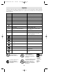
Symboles
Important : Certains des symboles suivants peuvent être utilisés sur votre outil. Veuillez les étudier et apprendre
leur signification. Une interprétation appropriée de ces symboles vous permettra d'utiliser l'outil de façon plus
efficace et plus sûre.
Symbole Nom Désignation/Explication
V Volts Tension (potentielle)
A Ampères Courant
Hz Hertz Fréquence (cycles par seconde)
W Watt Puissance
kg Kilogrammes Poids
min Minutes Temps
s Secondes Temps
Diamètre Taille des mèches de perceuse, meules,
etc.
n
0
Vitesse à vide Vitesse de rotation, à vide
.../min Tours ou mouvement alternatif par Tours, coups, vitesse en surface, orbites,
minute etc., par minute,
0 Position d'arrêt Vitesse zéro, couple zéro ...
1, 2, 3, ... Réglages du sélecteur Réglages de vitesse, de couple ou de
l, ll, lll, ... position. Un nombre plus élevé signifie
une vitesse plus grande.
Sélecteur variable à l'infini avec arrêt La vitesse augmente depuis le réglage 0
Flèche Action dans la direction de la flèche
Courant alternatif Type ou caractéristique du courant
Courant continu Type ou caractéristique du courant
Courant alternatif Type ou caractéristique du courant
ou continu
Construction classe II Désigne des outils construits avec double
isolation
Borne de terre borne de mise à la terre
Symbole d'avertissement Alerte l'utilisateur aux messages
d'avertissement.
Sceau Ni-Cad RBRCmc Désigne le programme de recyclage des piles
Ni-Cad.
0
Ce symbole signifie que cet
outil est approuvé par
Underwriters Laboratories.
Ce symbole signifie que cet
outil est approuvé par
l'Association canadienne de
normalisation.
Ce symbole signifie que
cet outil est approuvé
conformément aux normes
canadiennes par Underwriters
Laboratories.
Ce symbole
signifie que
cet outil se
conforme aux
normes
mexicaines
NOM.
Ce symbole signifie que cet outil
est approuvé par Underwriters
Laboratories et qu’il a été
homologué selon les normes
canadiennes par Underwriters
Laboratories.
BM 2610917139 6/02 7/10/02 10:50 AM Page 18

-19-
Description fonctionnelle et spécifications
Débranchez le bloc-pile de l'outil ou placez l'interrupteur à la position de blocage
ou d'arrêt avant d'effectuer tout assemblage ou réglage ou de changer les
accessoires. Ces mesures de sécurité préventives réduisent le risque d'une mise en marche accidentelle de
l'outil.
AVERTISSEMENT
!
Numéro Tension Régime Temps Numéro Tension Bloc
de chargeur nominale à vide de charge de chargeur nominale piles
53514 14.4 V n
0
13,000/min 1 hr. BC001-6 & BC016 120 V 60 Hz BAT040 et BAT038
53518 18 V n
0
13,000/min 1 hr. BC003, 4, 6, & BC016 120 V 60 Hz BAT026 et BAT025
Capacidades máximas
Profundidad de acepillad 0 - 1/16" (0 - 1,6 mm)
Profundidad de rebajado 0 - 5/16" (0 - 8 mm)
Anchura de corte 3-1/4" (82 mm)
Le chargeur BC006 nécessite une puissance d’alimentation
de 12 V CC.
NOTE : N’UTILISER QUE LES CHARGEURS
REPERTORIES CI-DESSUS
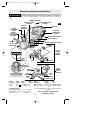
Rabot sans fil
BOUTON À
AILETTES
BUTÉE DE
PROFONDEUR
POUR FEUILLURE
(EN OPTION)
BOUTON DE
RÉGLAGE DE
PROFONDEUR
RACCORD
D’ÉVACUATION DES
COPEAUX
RACCORD D’ÉVACUATION DES COPEAUX
ÉCHELLE DE
PROFONDEUR
LEVIER DE SÉLECTION
DU RACCORD
INTERRUPTEUR À GÂCHETTE
BOUTON DE VERROUILLAGE
SUR ARRÊT
SEMELLE AVANT
GUIDE
INCLINABLE
BOUTON
ROND
SUPPORT
DE GUIDE
BOUTON À AILETTES
BOUTON À AILETTES
GUIDE
VIS
CAPOT DE COURROIE
GORGE EN VÉ
POUR
CHANFREINER
SUPPORT
DE GUIDE
ÉCHELLE
DES
LARGEURS
GUIDE
INCLINABLE
DE LUXE
(EN OPTION)
BOUTON À
AILETTES
GUIDE DE
LARGEUR
PARALLÈLE
STANDARD
FIG. 1
LES CHOIX DE PROFONDEUR
DE COUPE SONT ENVIRON :
1/16 po, 3/64 po, 1mm (•),
1/32 po, 1/64 po, & 1/128 po (•)
TOUCHES DE
DÉVERROUILLAGE
DES PILES
BLOC-PILES
VIS
BM 2610917139 6/02 7/10/02 10:50 AM Page 19

-20-
Assemblage
ÉVACUATION DES COPEAUX
Le rabot est muni de deux raccords d’évacuation de
copeaux sur lesquels on peut brancher soit un sac à
copeaux soit un aspirateur d’atelier avec un raccord
d’aspiration (Fig. 2) pour améliorer la propreté de
votre environnement de travail. Le sac à copeaux ou
le raccord d’aspiration peut être branché sur l’un ou
l’autre des raccords d’évacuation.
Quand le levier de sélection du raccord est en position
1, (vers l’avant de l’outil), les copeaux sont évacués à
gauche. En position 2 (vers l’arrière de l’outil), les
copeaux sont évacués à droite (Fig. 1).
FERS DE RABOT
Les fers de rabot sont
coupants et fragiles. Ils
doivent être manipulés avec soin pour éviter de se
blesser ou de les abîmer.
Les fers ont deux bords tranchants et ils peuvent être
retournés quand un des tranchants est émoussé ou
ébréché.
N'essayez pas d’affûter les fers ou d’utiliser des fers
ré-affûtés quels qu’ils soient. N’utilisez que des fers
conçus pour ce modèle. Toute autre fer risque de
causer des vibrations, de réduire la performance de la
machine ou d’être mal serrée dans le fer-lame.
CLÉ À FER ET
CASE DE RANGEMENT
Votre outil est pourvu d’une clé à fer qui est située
commodément dans la base de la poignée où elle est
toujours à la portée de la main et peu susceptible
d’être perdue ou égarée (Fig. 3).
RETOURNEMENT OU REMPLACEMENT DES FERS
Pour retourner ou remplacer le fer, desserrer les vis
de blocage à l’aide de la clé à fers. Une fois les vis
desserrées, faites glisser le fer dans le sens axial pour
le sortir du tambour en faisant bien attention
d’éloigner les doigts des bords tranchants du fer (Fig. 4).
Vous pouvez utiliser un morceau de bois pour cette
opération. Si le fer est encrassé et difficile à enlever,
vous pouvez le nettoyer avec du solvant, du diluant à
vernis ou de l’alcool.
Nettoyez toutes les surfaces avant de monter le fer
neuf. Cela assurera qu’il est positionné précisément et
permettra à l’outil de fonctionner correctement.
ALIGNEMENT DU FER
Pour que le rabotage soit régulier, le fer doit être à ras
des bords extérieurs des semelles avant et arrière.
Pour effectuer l’alignement, placez un règle ou un
morceau de bois le long de l’extérieur des semelles
avant et arrière, et ensuite enfoncez la lame jusqu’à ce
qu’elle touche tout juste le règle ou le morceau de
bois (Fig. 5).
Assurez-vous que le fer est bien en place dans la fente
du tambour.
Vous pouvez maintenant serrer les vis de blocage qui
tiennent le fer en place. Votre rabot est alors prêt à
l’emploi.
AVERTISSEMENT
!
FIG. 2
FIG. 4
FIG. 3
FIG. 5
SAC À COPEAUX
(EN OPTION)
RACCORDS
D’ÉVACUATION
RACCORD
D’ASPIRATION
FER
VIS DE
BLOCAGE
TAMBOUR
VIS DE
BLOCAGE
CLÉ À FER
CLÉ À FER DE
2,5 MM
TAMBOUR
RÈGLE
CLÉ À FER ET
CASE DE RANGEMENT
BM 2610917139 6/02 7/10/02 10:50 AM Page 20
La page est en cours de chargement...
La page est en cours de chargement...
La page est en cours de chargement...
La page est en cours de chargement...
La page est en cours de chargement...
La page est en cours de chargement...
La page est en cours de chargement...
La page est en cours de chargement...
La page est en cours de chargement...
La page est en cours de chargement...
La page est en cours de chargement...
La page est en cours de chargement...
La page est en cours de chargement...
La page est en cours de chargement...
La page est en cours de chargement...
La page est en cours de chargement...
La page est en cours de chargement...
La page est en cours de chargement...
La page est en cours de chargement...
La page est en cours de chargement...
-
 1
1
-
 2
2
-
 3
3
-
 4
4
-
 5
5
-
 6
6
-
 7
7
-
 8
8
-
 9
9
-
 10
10
-
 11
11
-
 12
12
-
 13
13
-
 14
14
-
 15
15
-
 16
16
-
 17
17
-
 18
18
-
 19
19
-
 20
20
-
 21
21
-
 22
22
-
 23
23
-
 24
24
-
 25
25
-
 26
26
-
 27
27
-
 28
28
-
 29
29
-
 30
30
-
 31
31
-
 32
32
-
 33
33
-
 34
34
-
 35
35
-
 36
36
-
 37
37
-
 38
38
-
 39
39
-
 40
40


Bosch Power Tools 53514 Manuel utilisateur
- Catégorie
- Raboteuses électriques
- Taper
- Manuel utilisateur
- Ce manuel convient également à
dans d''autres langues
- English: Bosch Power Tools 53514 User manual
- español: Bosch Power Tools 53514 Manual de usuario
Documents connexes
Autres documents
-
Skil PL5938-1A Le manuel du propriétaire
-
Skil 1565 AD Manuel utilisateur
-
-
Bosch PL1632 Manuel utilisateur
-
Bosch Appliances 1594K - NA Power Planer 3-1/4 Manuel utilisateur
-
-
Milwaukee 2623-21 Manuel utilisateur
-
-
Milwaukee M18 2623-20 Manuel utilisateur
-
Makita 2040 Le manuel du propriétaire