Yamaha A-S2100 Manuel utilisateur
- Catégorie
- Équipement musical supplémentaire
- Taper
- Manuel utilisateur
Ce manuel convient également à

© 2014 Yamaha Corporation
U
Printed in Malaysia VAA8450
Integrated Amplifier
Amplificateur Intégré
OWNER’S MANUAL
MODE D’EMPLOI

2 En
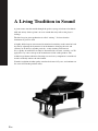
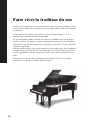
A Living Tradition in Sound
A piano comes into this world through the perfect synergy of advanced technical
skill and artistry. Such a piano can create sound that truly reflects the player’s
feelings.
The final stage in piano production is called “voicing”. It is here that the
instrument is given its soul.
A highly skilled expert concentrates his mind and sensitivity on the sound of each
key, finely adjusting the dynamic feel of the hammers, bringing the tone and
vibrancy of all 88 keys together perfectly; a truly stunning achievement.
It is a quality of sound that can only be determined by an astute, sensitive ear. We
apply this very same concept to the manufacture of our audio products. The
technician performs exhaustive listening tests and every component is considered,
in order to finally achieve the ideal sound.
Yamaha’s tradition of audio quality stretches back over 125 years, and continues to
live on in all Yamaha products today.

3 En
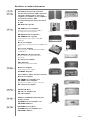
NP-S2000
Soavo-1
NS-10M
A-S3000
CD-S3000
NS-20
CA-1000
NS-690
B-1
PX-2
C-2
NS-1000M
A-1
B-6
B-2x
MX-10000
CX-10000
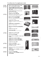
Excellence in Audio Achievement
First HiFi System introduced in 1920
We introduced numerous HiFi components
(turntables, FM/AM tuners, integrated
amplifiers, preamplifiers, power amplifiers
and speakers) in 1955 - 1965.
Natural Sound Speaker Series introduced
in 1967
NS-20 Monitor Speaker
CA-1000 Integrated Amplifier
Featuring A-Class operation, the CA-1000 set
the standard for integrated amplifiers.
NS-690 Natural Sound Speaker
NS-1000M Monitor Speaker
A truly legendary speaker still revered by HiFi
enthusiasts.
B-1 Power Amplifier
An innovative power amp that used vertical FETs in all
stages.
C-2 Control Amplifier
Received top prize at the Milan International Music
and HiFi Show.
NS-10M Studio Monitor Speaker
Became of the most popular studio monitors
in the world.
A-1 Integrated Amplifier
PX-2 Turntable
Yamaha’s first straight arm turntable.
B-6 Power Amplifier
Pyramid-shaped power amplifier.
GT-2000/L Turntable
First CD Player (CD-1) introduced in 1983
B-2x Power Amplifier
MX-10000 Power Amplifier and
CX-10000 Control Amplifier
Redefined the capabilities of separate components.
AX-1 Integrated Amplifier
GT-CD1 CD Player
MX-1 Power Amplifier and
CX-1 Preamplifier
Soavo-1 and Soavo-2 Natural Sound
Speaker Systems
A-S2000 Integrated Amplifier and
CD-S2000 CD Player
NP-S2000 Network Player
A-S3000 Integrated Amplifier and
CD-S3000 CD Player

4 En
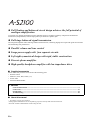
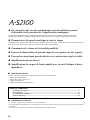
◆ Full floating and balanced circuit design achieves the full potential of
analogue amplification
An entirely new floating and balanced power amplifier achieves complete symmetry and permits full balanced
transmission (amplification) from the input jack to just before the speaker jack.
◆ Full-stage balanced signal transmission
The integrated amplifier offers full stage balanced transmission, combining high power output with good sound texture
and outstanding S/N performance.
◆ Parallel volume and tone control
◆ Large power supply with four separate circuits
◆ Left-right symmetrical design with rigid, stable construction
◆ Discrete phono amplifier
◆ High-quality headphone amplifier with low-impedance drive
■ Supplied accessories
Please check that you have received all of the following parts.
• Remote control
• Batteries (AAA, R03, UM-4) (×2)
• Power cable
• SAFETY BROCHURE
■ About this manual
• y indicates a tip for your operation.
• Photographs and illustrations are for explanatory purposes, and may differ from the actual unit.
• Read the “SAFETY BROCHURE” before using this unit.
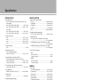
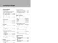
Contents
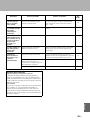
Controls and functions.......................................................................................................................................... 6
Connections.......................................................................................................................................................... 16
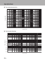
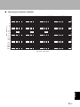
Specifications. ...................................................................................................................................................... 24
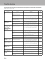
Troubleshooting................................................................................................................................................... 28

5 En
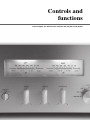
Controls and
functions
In this chapter, you will learn the controls and functions of A-S2100.

CONTROLS AND FUNCTIONS
6 En
Controls and functions
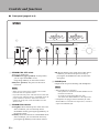
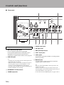
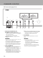
■ Front panel (pages 6 to 9)
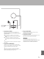
1 STANDBY/ON, OFF switch
Turns on or off this unit.
STANDBY/ON (upper position): In this position,
you can select STANDBY or ON,
using the p AMP key on the remote control.
OFF (lower position): The power of this unit is
turned off.
• When you turn on this unit, it will take a few seconds
before this unit can reproduce sound.
• If you disconnect the power cable from the AC outlet and
connect it again when this unit is in STANDBY mode, the
power of the unit is turned on. If the unit is not to be
operated for a long time, set the STANDBY/ON, OFF
switch to OFF.
2 STANDBY/ON indicator
Lit brightly: Shows that the power of the unit is ON.
In this condition, you can switch the unit to
STANDBY mode by pressing the p AMP key on
the remote control.
Lit dimly: Shows that the unit is in STANDBY mode.
In this condition, you can switch the unit on by
pressing the p AMP key on the remote control.
Off: Shows that the power of the unit is OFF. In this
condition, you can turn the power on only by
pressing the STANDBY/ON, OFF switch on the
front panel.
3 PHONES jack
Outputs audio for private listening with headphones.
• When headphones are plugged in:
– Both speaker sets connected to the SPEAKERS L/R CH
terminals are turned off.
– No signals are output at the PRE OUT jacks.
– You cannot select MAIN DIRECT as the input source.
• If headphones are plugged into the PHONES jack while
MAIN DIRECT is selected as the input source, no audio is
output at the PHONES jack.
METER
PEAK
OFF
VU
INPUT
BAL
CD
TUNER
LINE 1
PHONO
LINE 2
MAIN DIRECT
BASS
–+
TREBLE
–+
BALANCE
LR
STANDBY/ON PHONES TRIM
0
-6 +6
+12
SPEAKERS
A
OFF B
A+B
BI-WIRING
dB
OFF
1 2 3 4
5 6 7 8 9 :
Notes
Notes

7 En
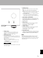
4 TRIM selector
Adjusts the volume level when headphones are
plugged in to avoid sudden changes in volume.
Choices: –6 dB, 0 dB, +6 dB, +12 dB
5 SPEAKERS selector
Turns on or off the sets of speakers connected to the
SPEAKERS L/R CH A and/or B terminals on the rear
panel, as follows.
OFF: Both sets of speakers are off.
A/B: The set of speakers connected to the A or B
terminals is on.
A+B BI-WIRING: Both sets of speakers are on.
If you use two sets (A and B), the impedance of each speaker
must be 8 Ω or higher.
6 METER selector
Switches the display of the meter to OFF, PEAK or
VU.
OFF: Turns off the meter and the illumination.
PEAK: Switches the meter to a peak level meter. The
peak level meter shows a momentarily highest
audio output level.
VU: Switches the meter to a VU (Volume Unit) level
meter. The VU level meter shows an effective
audio output value that is similar to human senses.
7 Meter displays (LEFT/RIGHT)
Show the audio output level of the left (LEFT) and
right (RIGHT) channels in VU or PEAK meter mode.
The VU or PEAK meter can be selected by the
METER selector.
8 BASS control
Increases or decreases the low frequency response.
The 0 position produces a flat response.
Control range: –10 dB to +10 dB
9 TREBLE control
Increases or decreases the high frequency response.
The 0 position produces a flat response.
Control range: –10 dB to +10 dB
0 BALANCE control
Adjusts the audio output balance of the left and right
speakers to compensate for sound imbalances caused
by speaker locations or listening room conditions.
• When both the BASS and TREBLE controls are set to the 0
position, audio signal bypasses the tone control circuitry.
• The BASS, TREBLE and BALANCE controls do not affect the
signals input at the MAIN IN jacks and signals output at the
LINE 2 REC jacks.
Caution
AUDIO MUTE
VOLUME
PHONO
MM
MC
Notes
English

8 En
Controls and functions
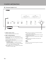
■ Front panel (pages 6 to 9)
A Remote control sensor
Receives signals from the remote control.
B INPUT selector/indicator
Selects the input source to be played back. The
indicator of the input source selected with the INPUT
selector lights.
The audio signals of the selected input source are also
output at the LINE 2 REC jacks.
MAIN DIRECT: Selects the component connected to
the MAIN IN jacks.
When MAIN DIRECT is selected as the input
source, the audio signals are not output at the PRE
OUT, LINE 2 REC and PHONES jacks.
LINE 1/LINE 2: Selects the component connected to
the LINE 1 or LINE 2 jacks.
BAL: Selects the component connected to the BAL
jacks (balanced XLR jacks).
CD: Selects the CD player connected to the CD jacks
(unbalanced RCA jacks).
TUNER: Selects the tuner connected to the TUNER
jacks.
PHONO: Selects the turntable connected to the
PHONO jacks.
When LINE 2 is selected, the audio signals are not output at
the LINE 2 REC jacks.
METER
PEAK
OFF
VU
INPUT
BAL
CD
TUNER
LINE 1
PHONO
LINE 2
MAIN DIRECT
BASS
–+
TREBLE
–+
BALANCE
LR
STANDBY/ON PHONES TRIM
0
-6 +6
+12
SPEAKERS
A
OFF B
A+B
BI-WIRING
dB
OFF
A B
Note

9 En
C PHONO switch
Selects the type of cartridge of the turntable connected
to the PHONO jacks on the rear panel.
MM: Choose this setting if the connected turntable
uses an moving magnet (MM) cartridge.
MC: Choose this setting if the connected turntable
uses an moving coil (MC) cartridge.
y
When you replace the cartridge, be sure to turn off this unit.
D AUDIO MUTE switch
Press downward to reduce the current volume level by
approximately 20 dB. Press again to restore the audio
output to the previous volume level.
y
You can also rotate the VOLUME control on the front panel
or press the VOLUME + or – key on the remote control to
resume the audio output.
E AUDIO MUTE indicator
Lights when the mute function is turned on with the
AUDIO MUTE switch.
F VOLUME control
Controls the volume level. This does not affect the
output level at the LINE 2 REC jacks.
The VOLUME control does not affect when you select
MAIN DIRECT as the input source. Adjust the volume level
using the volume control on the external amplifier connected
to the MAIN IN jacks.
AUDIO MUTE
VOLUME
PHONO
MM
MC
C
D E
F
Note
English

10 En
Controls and functions
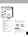
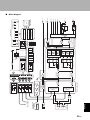
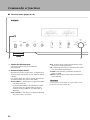
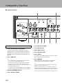
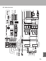
■ Rear panel
1 BAL (balanced) input jacks
One set of balanced input jacks is provided.
Set the ATTENUATOR selector and PHASE selector
appropriately for the playback component that is
connected. For details on these switches, refer to page 20.
2 PRE OUT jacks
y
• The PRE OUT jacks output the same channel signal as the
SPEAKERS L/R CH terminals.
• When you connect a stereo cable to the PRE OUT jacks to
drive the speakers using an external amplifier, it is not
necessary to use the SPEAKERS L/R CH terminals.
• The signal output at the PRE OUT jacks are affected by the
BASS and TREBLE control settings.
3 SPEAKERS L/R CH terminals
4 TUNER input jacks
5 PHONO input jacks
6 CD input jacks
7 GND (Ground) terminal
8 LINE 1 input jacks
9 LINE 2 jacks
PB (playback) input jacks and REC (recording) output
jacks are provided.
0 MAIN IN jacks
Use these jacks to connect an external component
equipped with a volume control.
y
When you select MAIN DIRECT as the input source, the
volume level is fixed.
Adjust the volume level using the volume control on the
external amplifier connected to the MAIN IN jacks when you
select MAIN DIRECT as the input source.
For the connection to the
MAIN IN
jacks, see pages 16 and 17.
GND
PHONO
LINE 1
CD
BAL
(-6dB)
ATT. INV.
BYPASS NORMAL
PHASE
ATTENUATOR
INPUT
SPEAKERS R CH
A
B
+
+
A OR B:4 MIN. /SPEAKER
A+B:8 MIN. /SPEAKER
R L
R R
R
L
TUNER
LINE2
REC
PB
MAIN IN
L
L
L
R
R R
L
L
PRE OUT
NORMAL (EIA)
+ HOT
- COLD
GND
12
3
1 2
3 4
5 6 7 8 9 0
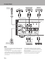
See page 16 for connection information.

11 En
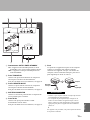
A AUTO POWER STANDBY switch
ON: The unit enters STANDBY mode automatically
if not operated for 8 hours.
OFF: The unit does not enter STANDBY mode
automatically.
B TRIGGER IN jack
Use this jack to connect an external component for the
trigger function.
For details on the connection, see page 22.
C REMOTE IN/OUT jacks
Use these jacks to connect an external component for
remote control.
For details on the connection, see page 21.
D SYSTEM CONNECTOR
Use this connector to connect a product testing device
for servicing.
E AC IN inlet
Use this inlet to plug in the supplied power cable.
For details on the connection, see page 19.
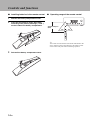
F Foot
The feet of this unit include built-in spikes. Using the
spikes can reduce the effect of vibrations on the set.
When using the spikes, remove the transport tape, then
remove the magnet foot by pulling it.
• Take care that the magnet foot is not accidentally
swallowed by small children.
• When using the feet’s built-in spikes, the spikes may
scratch the shelf or floor on which this unit is installed. Use
the magnet feet or appropriate supports when placing this
unit on expensive furniture, etc.
y
If this unit is unstable, you can adjust the foot height by
rotating it.
AUTO POWER STANDBY
ON
OFF
SPEAKERS L CH
A
B
+
+
TRIGGER
REMOTE
SYSTEM CONNECTOR
IN IN OUT
AC IN
A OR B:4 MIN. /SPEAKER
A+B:8 MIN. /SPEAKE
R
A B C D
E
3 F
Caution
Spike
Transport
tape
Magnet
foot
English

12 En
Controls and functions
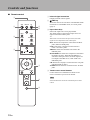
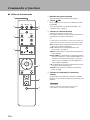
■ Remote control
1 Infrared signal transmitter
Outputs infrared control signals.
2 p AMP key
Turns this unit ON or switches it to STANDBY mode.
For details on STANDBY mode, see “Front panel”
(page 6).
3 Input select keys
Selects the input source to be played back.
The audio signals of the selected input source are
output at the LINE 2 REC jacks.
y
When LINE 2 is selected as the input source, the audio
signals are not output at the LINE 2 REC jacks.
BAL: Selects the component connected to the BAL
jacks (balanced XLR jacks).
LINE: Selects the component connected to the
LINE 1 or LINE 2 jacks.
PHONO: Selects the turntable connected to the
PHONO jacks.
MAIN DIRECT: Selects the component connected to
the MAIN IN jacks. When MAIN DIRECT is
selected as the input source, the audio signals are
not output at the PRE OUT, LINE 2 REC and
PHONES jacks.
CD: Selects the CD player connected to the CD jacks
(unbalanced RCA jacks).
TUNER: Selects the tuner connected to the TUNER
jacks
4 Yamaha tuner control buttons
Control functions of Yamaha tuner. Refer to the
owner’s manual of your tuner for details.
Some Yamaha tuners cannot be controlled by this remote
control.
4
2
1
3
8
9
5
7
6
AMP CD
OPEN/CLOSE
BAL
LINE LINE
PRESET
12
PHONO
MAIN DIRECT
CD TUNER
BAND
MUTE
SOURCE LAYER
VOLUME
Note

13 En
5 p CD key
Turns the Yamaha CD player ON or switches it to
STANDBY mode.
6 OPEN/CLOSE key
Opens/closes the disc tray of the Yamaha CD player.
Refer to the owner’s manual of your CD player for
details.
Some Yamaha CD players do not support the p CD key and/
or OPEN/CLOSE key of this remote control.
7 Yamaha CD player control keys
Control various functions of Yamaha CD player. Refer
to the owner’s manual of your CD player for details.
(Play): Starts playback.
(Pause): Pauses playback. Press the or to
resume playback.
(Stop): Stops playback.
/ (Skip): Skips to the next track, or skips
back to the beginning of the current track.
SOURCE: Selects the source to be played on the
Yamaha CD player. The playback source changes
each time this key is pressed.
LAYER: Switches the playback layer of a hybrid SA-
CD between SA-CD and CD.
8 VOLUME +/– keys
Control the volume level.
The VOLUME keys do not affect when you select MAIN
DIRECT as the input source. Adjust the volume level on the
external amplifier connected to the MAIN IN jacks.
9 MUTE key
Reduces the current volume level by approximately
20 dB. Press again to restore the audio output to the
previous volume level. Pressing the VOLUME + or –
key also cancels muting.
Note
Note
English

14 En
Controls and functions
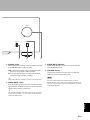
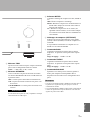
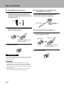
■ Installing batteries in the remote control
1 Remove the battery compartment cover.
2 Insert the two batteries (AAA, R03, UM-4)
according to the polarity markings (+ and –)
on the inside of the battery compartment.
3 Reinstall the battery compartment cover.
■ Operating range of the remote control
y
The remote control transmits a directional infrared beam. Be
sure to aim the remote control directly at the remote control
sensor on the front panel of this unit during operation.
2
1
3
30 30
Approximately 6 m
(20 ft)

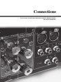
Connections
In this section, you will make connections between A-S2100, speakers,
and source components.

16 En
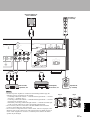
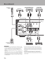
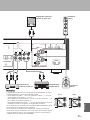
Connections
• Do not let the bare speaker wires touch each other or do not let
them touch any metal part of this unit. This could damage this
unit and/or the speakers.
• All connections must be correct: L (left) to L, R (right) to R,
“+” to “+”, and “–” to “–”. If the connections are faulty, no
sound will be heard from the speakers, and if the polarity of the
speaker connections is incorrect, the sound will be unnatural
and lack bass. Also, refer to the owner’s manual for each of
your components.
• Use RCA unbalanced cables to connect other components
except speakers. Use XLR balanced cables to connect a CD
player or network player with XLR balanced output jacks to the
BAL jacks of this unit.
• Connect your turntable to the GND terminal to reduce noise in
the signal. However, you may hear less noise without the
connection to the GND terminal for some turntables.
Notes
GND
PHONO
LINE1
CD
BAL
(-6dB)
ATT. INV.
BYPASS NORMAL
PHASE
ATTENUATOR
INPUT
SPEAKERS R CH
A
B
+
+
A OR B:4 MIN. /SPEAKER
A+B:8 MIN. /SPEAKER
R L
R R
R
L
TUNER
L
L
L
R
+
-
+
-
CD player with
RCA jacks
Speakers A
(R channel)
Speakers B
(R channel)
CD player or network
player with XLR jacks
Turntable
Ground
Tuner
BD player, etc.

17 En
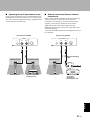
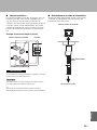
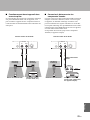
• Because the power amplifier of A-S2100 is of the floating balanced type, the
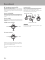
following types of connections are not possible.
– Connecting with the left channel “–” terminal and the right channel “–” terminal
as well as “+” terminals (Fig. 1).
– Connecting with the left channel “–” terminal and the right channel “–” terminal
inverted (cross connection, Fig. 2).
– Deliberately connecting with the left/right channel “–” terminals and metal part
on the rear panel of this unit, as well as accidentally touching them.
• Do not connect your active subwoofer to the SPEAKERS L/R CH terminal.
Connect it to the PRE OUT jacks of this unit.
• Do not connect a component with no volume control, such as a CD player, to the
MAIN IN jacks, as the volume level of the signals input to the MAIN IN jacks is
fixed. If such equipment is connected, a sound may burst, and the unit and/or
speaker may be damaged.
Notes
GND
LINE 1
-6dB)
TT. INV.
NORMAL
PHASE
TOR
LINE2
REC
PB
MAIN IN
L
R
R R
L
L
NORMAL (EIA)
+ HOT
- COLD
GND
12
3
PRE OUT
AUTO POWER STANDBY
ON
OFF
SPEAKERS L CH
A
B
+
+
TRIGGER
REMOTE
SYSTEM CONNECTOR
IN IN OUT
AC IN
A OR B:4 MIN. /SPEAKER
A+B:8 MIN. /SPEAKER
+–
+
-
CD recorder,
tape deck, etc.
Speakers A
(L channel)
Speakers B
(L channel)
External amplifier or
active subwoofer
Preamplifier,
AV receiver, etc.
English
+
–
+
–
L
R
+
–
+
–
L
R
+
–
+
–
L
R
+
–
+
–
L
R
Fig. 1 Fig. 2

18 En
Connections
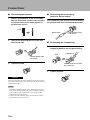
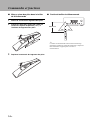
■ Connecting the speakers
1 Remove approximately 10 mm of insulation
from the end of each speaker cable and twist
the exposed wires of the cable together to
prevent short circuits.
2 Unscrew the knob and then insert the bare
wire into the hole.
3 Tighten the knob.
When loosening the knob of the speaker terminal, do not rotate it
excessively. The knob may come off and pose the danger of being
swallowed by a child.
• Touching the speaker terminal with a metallic rack may cause
short circuit and damage this unit. When installing the unit in a
rack, maintain a sufficient clearance to prevent the speaker
terminals from touching the rack.
• To reduce the risk of electric shock, do not touch the speaker
terminal when the unit is turned on.
■ Connecting the banana plug
(Except for Europe models)
First, tighten the knob and then insert the banana
plug into the end of the corresponding terminal.
■ Connecting the Y-shaped lug
1 Unscrew the knob and then sandwich the Y-
shaped lug between the ring part and base.
2 Tighten the knob.
Caution
Notes
10 mm
Hole for speaker cable:
6.0 mm dia.
Banana plug
Hole for banana plug:
3.95 mm dia.
Y-shaped lug
Slide
Terminal screw for Y-shaped
lug: 5.8 mm dia.

19 En
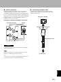
■ Bi-wire connection
The bi-wire connection separates the woofer from the
combined midrange and tweeter section. A bi-wire
compatible speaker has four binding post terminals. These
two sets of terminals allow the speaker to be split into two
independent sections. This split connects the mid and high
frequency drivers to one set of terminals and the low
frequency driver to the other pair.
Example of a bi-wiring connection (R channel)
To use the bi-wire connections, the impedance of each speaker
must be 8 Ω or higher.
Remove the shorting bars or bridges to separate the LPF (low
pass filter) and HPF (high pass filter) crossovers.
y
To use the bi-wire connections, switch the SPEAKERS selector
on the front panel to the A+B BI-WIRING position.
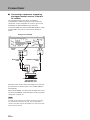
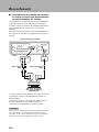
■ Connecting the power cable
Plug the power cable into the AC IN inlet when all
connections are complete, and then plug in the power
cable to the AC outlet.
Caution
Note
SPEAKERS R CH
A
B
+
+
A OR B:4 MIN. /SPEAKER
A+B:8 MIN. /SPEAKER
Rear panel of A-S2100 Speaker
AC IN
to an AC outlet
Rear panel of A-S2100
Supplied power cable
English

20 En
Connections
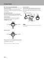
■ Connecting to the BAL jacks
Connect your CD player or network player with the XLR
balanced output jacks.
Set the ATTENUATOR selector and PHASE selector
located above the BAL
jacks according to the component
to be connected.
ATTENUATOR selector:
Select the allowable input level for the XLR balanced
input jacks. If sound from the connected component is
distorted, set the ATTENUATOR selector to ATT. (-6 dB).
PHASE selector:
Select the assignment of the HOT pin of the XLR
balanced input jacks (pin 2 HOT or pin 3 HOT).
NORMAL (pin 2 HOT)
INV. (pin 3 HOT)
Refer to the owner’s manual supplied with the connected
component and verify the assignment of the HOT pin of
its XLR balanced output jacks.
y
Yamaha CD players are set to NORMAL (pin 2 HOT).
XLR connectors:
When connecting, be sure to match the pins and insert the
connector of the “male” XLR balanced cable until you
hear a “click”. When disconnecting, pull out the “male”
XLR balanced cable while holding down the lever of the
BAL jack.
To select the component connected to the BAL jacks, set the input
source to BAL.
1: ground2: hot
3: cold
1: ground2: cold
3: hot
Note
“Female” XLR connector
“Male” XLR connector
Lever
BAL jack
La page est en cours de chargement...
La page est en cours de chargement...
La page est en cours de chargement...
La page est en cours de chargement...
La page est en cours de chargement...
La page est en cours de chargement...
La page est en cours de chargement...
La page est en cours de chargement...
La page est en cours de chargement...
La page est en cours de chargement...
La page est en cours de chargement...
La page est en cours de chargement...
La page est en cours de chargement...
La page est en cours de chargement...
La page est en cours de chargement...
La page est en cours de chargement...
La page est en cours de chargement...
La page est en cours de chargement...
La page est en cours de chargement...
La page est en cours de chargement...
La page est en cours de chargement...
La page est en cours de chargement...
La page est en cours de chargement...
La page est en cours de chargement...
La page est en cours de chargement...
La page est en cours de chargement...
La page est en cours de chargement...
La page est en cours de chargement...
La page est en cours de chargement...
La page est en cours de chargement...
La page est en cours de chargement...
La page est en cours de chargement...
La page est en cours de chargement...
La page est en cours de chargement...
La page est en cours de chargement...
La page est en cours de chargement...
La page est en cours de chargement...
La page est en cours de chargement...
La page est en cours de chargement...
La page est en cours de chargement...
-
 1
1
-
 2
2
-
 3
3
-
 4
4
-
 5
5
-
 6
6
-
 7
7
-
 8
8
-
 9
9
-
 10
10
-
 11
11
-
 12
12
-
 13
13
-
 14
14
-
 15
15
-
 16
16
-
 17
17
-
 18
18
-
 19
19
-
 20
20
-
 21
21
-
 22
22
-
 23
23
-
 24
24
-
 25
25
-
 26
26
-
 27
27
-
 28
28
-
 29
29
-
 30
30
-
 31
31
-
 32
32
-
 33
33
-
 34
34
-
 35
35
-
 36
36
-
 37
37
-
 38
38
-
 39
39
-
 40
40
-
 41
41
-
 42
42
-
 43
43
-
 44
44
-
 45
45
-
 46
46
-
 47
47
-
 48
48
-
 49
49
-
 50
50
-
 51
51
-
 52
52
-
 53
53
-
 54
54
-
 55
55
-
 56
56
-
 57
57
-
 58
58
-
 59
59
-
 60
60


Yamaha A-S2100 Manuel utilisateur
- Catégorie
- Équipement musical supplémentaire
- Taper
- Manuel utilisateur
- Ce manuel convient également à
dans d''autres langues
- English: Yamaha A-S2100 User manual
Documents connexes
-
Yamaha A-S3000 Le manuel du propriétaire
-
Yamaha A-S2100 Le manuel du propriétaire
-
Yamaha C-5000 Le manuel du propriétaire
-
Yamaha AS1000 - Amplifier Le manuel du propriétaire
-
-
-
-
-
Yamaha A-S1100 Silver/Piano Black Manuel utilisateur
-
Autres documents
-
Technics SU-G700 Operating Instructions Manual
-
-
 Accuphase E-213 Manuel utilisateur
-
Sony TA-E1 Operating Instructions (primary manual) Manuel utilisateur
-
JVC SX-DW303 Manuel utilisateur
-
Panasonic SUR1000E Mode d'emploi
-
 Sequenz SonicBar Manuel utilisateur
-
-
ONKYO A-1VL Le manuel du propriétaire

