Cabletron Systems MultiSwitch 700 Overview And Setup Manual
- Catégorie
- Châssis d'équipement de réseau
- Taper
- Overview And Setup Manual
Ce manuel convient également à

DIGITAL MultiSwitch 700
DLM6C-AA
Overview and Setup Guide


DIGITAL MultiSwitch 700
DLM6C-AA
Overview and Setup Guide
Part Number: 9032610
September1998
This guide describes how to install and configure the DIGITAL MultiSwitch
700 DLM6C-AA chassis.
Revision/Update Information: This is a new document.

Cabletron Systems reserves the right to make changes in specifications and other information
contained in this document without prior notice. The reader should in all cases consult Cabletron
Systems to determine whether any such changes have been made.
The hardware, firmware, or software described in this manual is subject to change without notice.
IN NO EVENT SHALL CABLETRON SYSTEMS BE LIABLE FOR ANY INCIDENTAL,
INDIRECT, SPECIAL, OR CONSEQUENTIAL DAMAGES WHATSOEVER (INCLUDING BUT
NOT LIMITED TO LOST PROFITS) ARISING OUT OF OR RELATED TO THIS MANUAL OR
THE INFORMATION CONTAINED IN IT, EVEN IF CABLETRON SYSTEMS HAS BEEN
ADVISED OF, KNOWN, OR SHOULD HAVE KNOWN, THE POSSIBILITY OF SUCH
DAMAGES.
Copyright 1998 by Cabletron Systems, Inc., P.O. Box 5005, Rochester, NH 03866-5005
All Rights Reserved
Printed in the United States of America
SPECTRUM and LANVIEW are registered trademarks of Cabletron Systems, Inc.
DIGITAL and the DIGITAL logo are trademarks of Digital Equipment Corporation.
All other product names mentioned in this manual may be trademarks or registered trademarks of
their respective companies.United States Government Restricted RightsUnited States Government
Restricted Rights
The enclosed product (a) was developed solely at private expense; (b) contains “restricted computer
software” submitted with restricted rights in accordance with Section 52227-19 (a) through (d) of the
Commercial Computer Software - Restricted Rights Clause and its successors, and (c) in all respects
is proprietary data belonging to Cabletron and/or its suppliers.
UNITED STATES GOVERNMENT RESTRICTED RIGHTS
The enclosed product (a) was developed solely at private expense; (b) contains “restricted computer
software” submitted with restricted rights in accordance with Section 52227-19 (a) through (d) of the
Commercial Computer Software - Restricted Rights Clause and its successors, and (c) in all respects
is proprietary data belonging to Cabletron and/or its suppliers.
For Department of Defense units, the product is licensed with “Restricted Rights” as defined in the
DoD Supplement to the Federal Acquisition Regulations, Section 52.227-7013 (c) (1) (ii) and its
successors, and use, duplication, disclosure by the Government is subject to restrictions as set forth in
subparagraph (c) (1) (ii) of the Rights in Technical Data and Computer Software clause at
252.227-7013. Cabletron Systems, Inc., 35 Industrial Way, Rochester, New Hampshire 03867-0505.

FCC Notice — Class A Computing Device:
This equipment generates, uses, and may emit radio frequency energy. The equipment has been type
tested and found to comply with the limits for a Class A digital device pursuant to Part 15 of FCC
rules, which are designed to provide reasonable protection against such radio frequency interference.
Operation of this equipment in a residential area may cause interference in which case the user at his
own expense will be required to take whatever measures may be required to correct the interference.
Any modifications to this device - unless expressly approved by the manufacturer - can void the user's
authority to operate this equipment under part 15 of the FCC rules.
DOC Notice — Class A Computing Device:
This digital apparatus does not exceed the Class A limits for radio noise emissions from digital
apparatus set out in the Radio Interference Regulations of the Canadian Department of
Communications.
Le présent appareil numérique n’émet pas de bruits radioélectriques dépassant les limites applicables
aux appareils numériques de la class A prescrites dans le Règlement sur le brouillage radioélectrique
édicté par le ministère des Communications du Canada.
VCCI Notice — Class A Computing Device:
Taiwanese Notice — Class A Computing Device:
CE Notice — Class A Computing Device:
Warning!
This is a Class A product. In a domestic environment, this product may cause radio interference, in
which case the user may be required to take adequate measures.
Achtung!
Dieses ist ein Gerät der Funkstörgrenzwertklasse A. In Wohnbereichen können bei Betrieb dieses
Gerätes Rundfunkstörungen auftreten, in welchen Fällen der Benutzer für entsprechende
Gegenma
ßnahmen verantwortlich ist.
Avertissement!
Cet appareil est un appareil de Classe A. Dans un environnement résidentiel cet appareil peut
provoquer des brouillages radioélectriques. Dans ce cas, il peut être demandé à l'utilisateur de prendre
les mesures appropriées.

CABLETRON SYSTEMS, INC. PROGRAM LICENSE AGREEMENT
IMPORTANT: Before utilizing this product, carefully read this License Agreement.
This document is an agreement between you, the end user, and Cabletron Systems, Inc. (“Cabletron”)
that sets forth your rights and obligations with respect to the Cabletron software program (the
“Program”) contained in this package. The Program may be contained in firmware, chips or other
media. BY UTILIZING THE ENCLOSED PRODUCT, YOU ARE AGREEING TO BECOME
BOUND BY THE TERMS OF THIS AGREEMENT, WHICH INCLUDES THE LICENSE AND
THE LIMITATION OF WARRANTY AND DISCLAIMER OF LIABILITY. IF YOU DO NOT
AGREE TO THE TERMS OF THIS AGREEMENT, PROMPTLY RETURN THE UNUSED
PRODUCT TO THE PLACE OF PURCHASE FOR A FULL REFUND.
CABLETRON SOFTWARE PROGRAM LICENSE
1. LICENSE. You have the right to use only the one (1) copy of the Program provided in this
package subject to the terms and conditions of this License Agreement.
You may not copy, reproduce or transmit any part of the Program except as permitted by the
Copyright Act of the United States or as authorized in writing by Cabletron.
2. OTHER RESTRICTIONS
. You may not reverse engineer, decompile, or disassemble the
Program.
3. APPLICABLE LAW
. This License Agreement shall be interpreted and governed under the laws
and in the state and federal courts of New Hampshire. You accept the personal jurisdiction and
venue of the New Hampshire courts.
EXCLUSION OF WARRANTY AND DISCLAIMER OF LIABILITY
1. EXCLUSION OF WARRANTY. Except as may be specifically provided by Cabletron in
writing, Cabletron makes no warranty, expressed or implied, concerning the Program (including
its documentation and media).
CABLETRON DISCLAIMS ALL WARRANTIES, OTHER THAN THOSE SUPPLIED TO
YOU BY CABLETRON IN WRITING, EITHER EXPRESSED OR IMPLIED, INCLUDING
BUT NOT LIMITED TO IMPLIED WARRANTIES OF MERCHANTABILITY AND
FITNESS FOR A PARTICULAR PURPOSE, WITH RESPECT TO THE PROGRAM, THE
ACCOMPANYING WRITTEN MATERIALS, AND ANY ACCOMPANYING HARDWARE.
2. NO LIABILITY FOR CONSEQUENTIAL DAMAGES
. IN NO EVENT SHALL
CABLETRON OR ITS SUPPLIERS BE LIABLE FOR ANY DAMAGES WHATSOEVER
(INCLUDING, WITHOUT LIMITATION, DAMAGES FOR LOSS OF BUSINESS,
PROFITS, BUSINESS INTERRUPTION, LOSS OF BUSINESS INFORMATION, SPECIAL,
INCIDENTAL, CONSEQUENTIAL, OR RELIANCE DAMAGES, OR OTHER LOSS)
ARISING OUT OF THE USE OR INABILITY TO USE THIS CABLETRON PRODUCT,
EVEN IF CABLETRON HAS BEEN ADVISED OF THE POSSIBILITY OF SUCH
DAMAGES. BECAUSE SOME STATES DO NOT ALLOW THE EXCLUSION OR
LIMITATION OF LIABILITY FOR CONSEQUENTIAL OR INCIDENTAL DAMAGES, OR
ON THE DURATION OR LIMITATION OF IMPLIED WARRANTIES, IN SOME
INSTANCES THE ABOVE LIMITATIONS AND EXCLUSIONS MAY NOT APPLY TO
YOU.

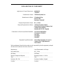
DECLARATION OF CONFORMITY
Application of Council Directive(s): 89/336/EEC
73/23/EEC
Manufacturer’s Name: Cabletron Systems, Inc.
Manufacturer’s Address: 35 Industrial Way
PO Box 5005
Rochester, NH 03867
European Representative Name: Mr. J. Solari
European Representative Address: Cabletron Systems Limited
Nexus House, Newbury Business Park
London Road, Newbury
Berkshire RG13 2PZ, England
Conformance to Directive(s)/Product Standards: EC Directive 89/336/EEC
EC Directive 73/23/EEC
EN 55022
EN 50082-1
EN 60950
Equipment Type/Environment: Networking Equipment, for use in a
Commercial or Light Industrial
Environment.
We the undersigned, hereby declare, under our sole responsibility, that the equipment packaged
with this notice conforms to the above directives.
Manufacturer Legal Representative in Europe
Mr. Ronald Fotino Mr. J. Solari
___________________________________ ___________________________________
Full Name Full Name
Principal Compliance Engineer Managing Director - E.M.E.A.
___________________________________ ___________________________________
Title Title
Rochester, NH, USA Newbury, Berkshire, England
___________________________________ ___________________________________
Location Location


DLM6C-AA Overview and Setup Guide ix
CONTENTS
PREFACE
Using This Guide............................................................................xi
Structure of This Guide...................................................................xi
Document Conventions.................................................................xii
Using the DIGITAL MultiSwitch 700 Manual Set...........................xii
Correspondence...........................................................................xiii
Documentation Comments..............................................xiii
World Wide Web..............................................................xiii
Getting Help..................................................................................xiii
SAFETY
Overview........................................................................................xv
Safety Requirements....................................................................xvi
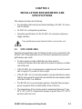
CHAPTER 1 INTRODUCTION
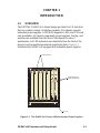
1.1 Overview......................................................................................1-1
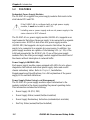
1.2 Features ......................................................................................1-2
CHAPTER 2 INSTALLATION REQUIREMENTS AND
SPECIFICATIONS
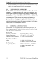
2.1 Site Guidelines ............................................................................2-1
2.2 Configuration Guidelines.............................................................2-2
2.3 Operating Specifications..............................................................2-2
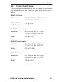
2.3.1 Physical Specifications ...................................................2-3
2.3.2 Power Supply Requirements ..........................................2-4
2.4 LEDs............................................................................................2-4
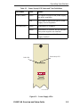
2.4.1 Power Supply LEDs........................................................2-4
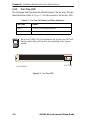
2.4.2 Fan Tray LED..................................................................2-6
CHAPTER 3 DLM6C-AA SETUP
3.1 Unpacking the DLM6C-AA ..........................................................3-1
3.2 Setting Up the DLM6C-AA...........................................................3-2
3.2.1 Installation Order.............................................................3-2
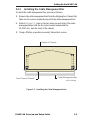
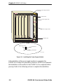
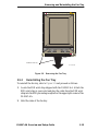
3.2.2 Installing the Cable Management Bar.............................3-3
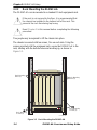
3.2.3 Rack Mounting the DLM6C-AA.......................................3-4
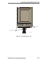
3.2.4 Attaching the ESD Wrist Strap........................................3-5
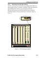
3.2.5 Installing a Power Supply Module...................................3-6
3.2.6 Installing DLM6C-AA Interface Modules.........................3-9

Contents
x DLM6C-AA Overview and Setup Guide
3.3 Powering Up a DLM6C-AA with an AC Power Supply...............3-11
3.4 Powering Up a DLM6C-AA with a DC Power Supply.................3-11
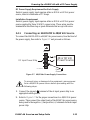
3.4.1 Connecting an HA205-MD to 48/60 Vdc Source...........3-13
3.5 Removing and Reinstalling the Fan Tray...................................3-14
3.5.1 Removing the Fan Tray.................................................3-14
3.5.2 Reinstalling the Fan Tray ..............................................3-15

DLM6C-AA Overview and Setup Guide xi
PREFACE
Welcome to the DIGITAL MultiSwitch 700 DLM6C-AA Overview and Setup
Guide
. This guide explains how to set up and configure the DLM6C-AA
chassis.
USING THIS GUIDE
Read through this guide completely to familiarize yourself with its
contents and to gain an understanding of the features and capabilities of
the DLM6C-AA chassis. This guide lists the features and options of the
chassis, explains how to remove and reinstall the fan tray, and explains
how to install the power supplies, modules, and the cable management
bar. A general working knowledge of data communications networks is
helpful when setting up the DLM6C-AA chassis.
STRUCTURE OF THIS GUIDE
This guide is organized as follows:
Chapter 1, Introduction, discusses the features and capabilities of the
DLM6C-AA.
Chapter 2, Installation Requirements and Specifications, lists the
location requirements that must be met before installing the DLM6C-AA
in a cabinet or rack. This chapter also includes some configuration
guidelines, environmental guidelines, and operating specifications for the
DLM6C-AA and related power supply modules.
Chapter 3, DLM6C-AA Setup, contains instructions for rack mounting
the DLM6C-AA, removing and reinstalling the fan tray, installing the
power supplies, modules, and cable management bar, and powering up the
DLM6C-AA.
In this document, the DIGITAL MultiSwitch 700 DLM6C-AA
chassis is referred to as either the “DLM6C-AA” or the
“chassis.”

xii DLM6C-AA Overview and Setup Guide
DOCUMENT CONVENTIONS
Throughout this guide, the following symbols are used to call attention to
important information.
USING THE DIGITAL MULTISWITCH 700 MANUAL SET
Other manuals have been developed for the interface modules that can be
installed in the DLM6C-AA chassis. These manuals explain how to
install the modules into the DLM6C-AA chassis, how to attach cable
segments to the modules, and how to configure the modules using Local
Management after installation is complete. Specifications for all modules
are included in each manual.
Each manual in this set assumes that the qualified personnel installing the
module has a general working knowledge of data communications
networks and their physical layer components.
Note symbol. Calls the reader’s attention to any item of
information that may be of special importance.
!
Caution symbol. Contains information essential to avoid
damage to the equipment.
Electrical Hazard Warning symbol. Warns against an action
that could result in the personal injury or death due to an
electrical hazard.

DLM6C-AA Overview and Setup Guide xiii
CORRESPONDENCE
Documentation Comments
If you have comments or suggestions about this manual, send them to
DIGITAL Network Products:
World Wide Web
To locate product-specific information, refer to the DIGITAL Network
products Home Page on the World Wide Web at the following locations:
GETTING HELP
Contact your DIGITAL representative for technical support. Before
calling, have the following information ready:
• A description of the failure
• A description of any action(s) already taken to resolve the problem
(e.g., changing mode switches, rebooting the unit, etc.)
• A description of your network environment (layout, cable type, etc.)
• Network load and frame size at the time of trouble (if known)
• The device history (i.e., have you returned the device before, is this a
recurring problem, etc.)
Attn.: Documentation Project Manager
E-MAIL: doc_quality@lkg.mts.dec.com
North America: http://www.networks.digital.com
Europe: http://www.networks.europe.digital.com
Asia Pacific: http://www.networks.digital.com.au


DLM6C-AA Overview and Setup Guide xv
SAFETY
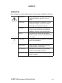
OVERVIEW
Any warning or caution that appears in this manual is defined as follows:
WARNING Warns against an action that could result in
equipment damage, personal injury, or
death.
VORSICHT Warnt den Benutzer vor Aktionen, die das
Gerät beschädigen, Personen verletzen
oder sogar zum Tot führen könnten.
DANGER Déconseille à l'utilisateur d'exécuter une
action pouvant entraîner des dommages
matériels, corporels voire même la mort.
AVISO Previene contra una acción que podría
dañar el equipo, provocar daños personales
o la muerte.
CAUTION Contains information essential to avoid dam-
age to the equipment.
ACHTUNG Liefert wichtige Informationen, um einen
Geräteschaden zu vermeiden.
ATTENTION Informations indispensables permettant
d'éviter les dommages matériels.
PRECAUCIÓN Contiene información esencial para evitar
daños al equipo.
!

Safety
xvi DLM6C-AA Overview and Setup Guide
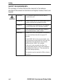
SAFETY REQUIREMENTS
The warnings or cautions that must be observed for the hardware
described in this manual are listed below in English, German, French, and
Spanish.
WARNING Only qualified personnel should install or
service this unit.
VORSICHT Diese Einheit darf nur von qualifizierten Fach-
leuten installiert oder gewartet werden.
DANGER L’installation et la maintenance de cet appar-
eil sont réservées à un personnel qualifié.
AVISO Sólo el personal cualificado debe instalar o
dar mantenimiento a esta unidad.
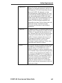
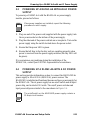
WARNING If theDLM6C-AA is to be placed on a shelving
unit, the shelf must be able to support 75
pounds.
If the DLM6C-AA is to be rack mounted, care
must be taken to ensure that the rack used will
support the unit and that the rack remains
stable with the DLM6C-AA installed.
If the rack is not secured to the floor, it is
recommended that the chassis be installed in
the bottom half of the rack. This prevents the
rack from being top heavy.
Two people may be required to lift the chassis
into place.

Safety Requirements
DLM6C-AA Overview and Setup Guide xvii
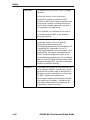
VORSICHT Wenn der DLM6C-AA auf einem Regal plaziert
werden soll, muß das Regal eine Last von ca.
34 Kilogramm (75 Pfund) unterstützen können.
Wenn der DLM6C-AA dagegen in einem
Einschubgehäuse installiert werden soll, muß
der Einschub die Einheit stützen können und
nach der Installation des DLM6C-AA stabil
bleiben. Wenn das Einschubgehäuse nicht am
Boden befestigt ist, wird die Installation im
unteren Teil des Gehäuses empfohlen, da
andernfalls der obere Teil zu schwer und nicht
stabil sein könnte. Eventuell sind zwei
Personen zum Einsetzen in das Gehäuse
erforderlich.
DANGER Si l'appareil DLM6C-AA doit être monté sur un
support, celui-ci doit pouvoir accepter un poids
de 34 kg. Si l'appareil doit être monté sur un
rack, assurez-vous que celui-ci est prévu pour
cela et qu'il restera stable une fois l'appareil
installé. Si le rack n'est pas fixé au sol, il est
recommandé d'installer le châssis dans la
partie inférieure du rack, pour ne pas
surcharger la partie supérieure. Prévoir deux
personnes pour insérer le châssis.
AVISO Si el DLM6C-AA se va a colocar en una unidad
de estantes, el estante deberá ser capaz de
aguantar 34 kg. Si el DLM6C-AA se va a
montar en bastidor, es preciso asegurarse de
que el bastidor tenga capacidad para aguantar
la unidad y de que permanecerá estable una
vez instalado el DLM6C-AA. Si el bastidor no
está fijado al suelo, se recomienda instalar el
chasis en la mitad inferior del bastidor, para
evitar que la parte superior del mismo se
venza por exceso de peso. Es conveniente
pedir la ayuda de otra persona para colocar el
chasis en su lugar.

Safety
xviii DLM6C-AA Overview and Setup Guide
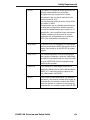
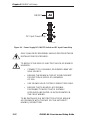
WARNING To reduce the risk of electric shock or energy
hazards:
Ensure the branch circuit overcurrent
protection is rated at a minimum of 25 A.
Use the 10 AWG solid copper conductors only.
Ensure that a readily accessible disconnect
device that is suitably approved and rated, is
incorporated in the field wiring.
To be installed in a restricted access area in
accordance with the NEC or the authority
having jurisdiction.
VORSICHT Um Elektroschock und Stromgefahr zu
vermeiden: Stellen Sie sicher, daß die
Überstromschutzeinrichtung des
Verzweigungsstromkreises auf mindestens 25
A eingestellt ist. Verwenden Sie nur 10
AWG-Kupferhalbleiter. Ein genehmigtes, leicht
zugängliches Trenngerät mit angemessener
Strom- und Spannungsleistung muß in der
Feldverkabelung integriert sein. Die Installation
darf nur in einem Gebiet mit begrenztem Zutritt
entsprechend dem NEC oder der zuständigen
rechtlichen Behörde erfolgen.
DANGER Pour réduire les risques de choc électrique et
de tout danger afférent : assurez-vous que la
protection du circuit accepte au minimum 25 A.
N'utilisez que des conducteurs en cuivre type
10 AWG. Vérifiez qu'un appareil de
déconnexion adapté et facilement accessible
soit installé sur la câblage. L'installation doit
être faite conformément aux réglements en
vigueur dans le pays concerné.
La page est en cours de chargement...
La page est en cours de chargement...
La page est en cours de chargement...
La page est en cours de chargement...
La page est en cours de chargement...
La page est en cours de chargement...
La page est en cours de chargement...
La page est en cours de chargement...
La page est en cours de chargement...
La page est en cours de chargement...
La page est en cours de chargement...
La page est en cours de chargement...
La page est en cours de chargement...
La page est en cours de chargement...
La page est en cours de chargement...
La page est en cours de chargement...
La page est en cours de chargement...
La page est en cours de chargement...
La page est en cours de chargement...
La page est en cours de chargement...
La page est en cours de chargement...
La page est en cours de chargement...
La page est en cours de chargement...
La page est en cours de chargement...
La page est en cours de chargement...
La page est en cours de chargement...
La page est en cours de chargement...
La page est en cours de chargement...
La page est en cours de chargement...
La page est en cours de chargement...
La page est en cours de chargement...
La page est en cours de chargement...
La page est en cours de chargement...
La page est en cours de chargement...
-
 1
1
-
 2
2
-
 3
3
-
 4
4
-
 5
5
-
 6
6
-
 7
7
-
 8
8
-
 9
9
-
 10
10
-
 11
11
-
 12
12
-
 13
13
-
 14
14
-
 15
15
-
 16
16
-
 17
17
-
 18
18
-
 19
19
-
 20
20
-
 21
21
-
 22
22
-
 23
23
-
 24
24
-
 25
25
-
 26
26
-
 27
27
-
 28
28
-
 29
29
-
 30
30
-
 31
31
-
 32
32
-
 33
33
-
 34
34
-
 35
35
-
 36
36
-
 37
37
-
 38
38
-
 39
39
-
 40
40
-
 41
41
-
 42
42
-
 43
43
-
 44
44
-
 45
45
-
 46
46
-
 47
47
-
 48
48
-
 49
49
-
 50
50
-
 51
51
-
 52
52
-
 53
53
-
 54
54


Cabletron Systems MultiSwitch 700 Overview And Setup Manual
- Catégorie
- Châssis d'équipement de réseau
- Taper
- Overview And Setup Manual
- Ce manuel convient également à
dans d''autres langues
- English: Cabletron Systems MultiSwitch 700
Documents connexes
-
 Cabletron Systems DELHE-UA Manuel utilisateur
-
 Cabletron Systems GIGAswitch GSR-8 Getting Started Manual
-
 Cabletron Systems ELS100 Quick Installation Manual
-
 Cabletron Systems SmartSTACK EPIM1000-S1LX 1000BASE-LX Quick Installation Manual
-
 Cabletron Systems TPT-D4 Manuel utilisateur
-
Cabletron Systems FRM Installation & Setup Manual
-
 Cabletron Systems TPFOT-2 Manuel utilisateur
-
 Cabletron Systems EPIM-3PS Guide d'installation


