
MI 2100
MI 2100 07/2002 ri
English
Français
Deutsch
Nederlands
Italiano
Español
Dansk
Owner’s manual and mounting instruction
Mode d’emploi et manuel d’installation
Bedienungs- und Einbauanleitung
Gebruiksaanwijzing en inbouwhandleiding
Istruzioni d’uso e d’installazione
Instrucciones de manejo y de montaje
Betjeningsvejledning og monteringsanvisning
Owner’s manual and mounting instruction
Mode d’emploi et manuel d’installation
Bedienungs- und Einbauanleitung
Gebruiksaanwijzing en inbouwhandleiding
Istruzioni d’uso e d’installazione
Instrucciones de manejo y de montaje
Betjeningsvejledning og monteringsanvisning

Attention
Watching TV while driving can easily distract your attention from traffic. To avoid the risk
of injury of passengers or other road users, the driver should not watch TV while driving.
Please follow local regulations applying to in-car TV and video.
Attention
Regarder la télévision pendant le voyage peut réduire considérablement votre attention
et vous détourner des événements du trafic. Le conducteur ne doit pas regarder la
télévision pendant le voyage afin de ne pas mettre en danger les passagers ni les autres
participants au trafic routier. Respectez s.v.p. les prescriptions locales en matière de
télévision dans le véhicule.
Achtung
Fernsehen während der Fahrt kann Ihre Aufmerksamkeit stark reduzieren und vom
Verkehrsgeschehen ablenken. Um eine Gefährdung der Insassen und anderer Verkehrsteil
-
nehmer zu vermeiden, sollte der Fahrer nicht während der Fahrt fernsehen. Beachten Sie
bitte die lokalen Vorschriften bezüglich des Fernsehens im Fahrzeug.
Attentie
Als u tijdens het rijden naar de televisie kijkt, kan dit uw attentie sterk verminderen en
van het verkeer afleiden. Om te voorkomen dat de inzittenden en andere weggebruikers
in gevaar worden gebracht, dient de bestuurder tijdens het rijden niet naar de TV te
kijken. Houd u bovendien aan de ter plaatse geldende voorschriften met betrekking tot
televisiekijken in de auto.
Attenzione
Guardare la televisione durante la marcia può ridurre notevolmente l'attenzione e perciò
distrarre il guidatore dalle condizioni di traffico. Il guidatore, per evitare di mettere in
pericolo i propri passeggeri e gli altri cittadini, non deve quindi mai osservare il televisore
durante la marcia. Si raccomanda di rispettare le norme nazionali che regolamentano la
visione di schermi televisivi negli autoveicoli.
Atención
Ver televisión durante el trayecto puede reducir considerablemente su atención al tráfico.
Para no poner en peligro la salud de los ocupantes del vehículo y de los demás usuarios de
la vía pública, el conductor no debiera ver televisión al conducir. Tenga presente la regla
-
mentación vigente.
Observera
Att se på TV under färd kan starkt reducera Er uppmärksamhet och avleda den från vad
som händer i trafiken. För att undvika fara för passagerare och andra trafikanter bör föra
-
ren inte se på TV under färd. Iakttag lokala föreskrifter angående TV i fordon.
2

3
grey
grau
gris
green
grün
vert
red
rot
rouge
yellow
gelb
jaune
black
schwarz
noir
REMOTE IN
REMOTE OUT
Power
blue/white
blau/weiss
bleu/blanc
R
1
2
3
4
5
Monitor *
12 V
LINE OUT - L
LINE OUT - R
VIDEO OUT
PC 5000/5100 *
RV 5100 *
DV 6100 *
TV 5100 *
* Accessory
MI 2100
0.5 A
3.15 A

Notes on operating instructions
The following reading aids are used to simplify these operating instructions:
☞
requests you to perform an action.
❏
identifies a list.
A
Safety instructions and warnings contain important information for the safe use of the unit.
Failure to observe this information may result in a risk of damage or injury. Therefore, please ob
-
serve this information with particular care.
WARNING:
Important information for safe operation
A
For safety reasons, the driver should not watch television or operate a video source (DVD
player, TV tuner, etc.) when driving. Please note that it is illegal in certain countries to watch or
operate the television when driving.
A
When setting the volume, please make sure that traffic noises (horns, sirens, emergency
vehicles, etc.) are still audible.
Features
❏
Automatic switching of video sources.
❏
Audio / video input (RCA/Cinch).
❏
Volume adaptation of connected video source.
Function
The MI 2100 multimedia interface enables building of a multimedia system, with little effort.
For this purpose, any video source (e.g. VDO Dayton DVD player DV 6100), a VDO Dayton
reversing camera as well as a navigation computer can be connected to the MI 2100.
Switching of the relevant video source (AV, reversing camera or navigation system) is per-
formed automatically by the MI 2100, depending upon the traffic situation and configura
-
tion of the multimedia system.
Monitor stand-by
The MI 2100 is switched on and off together with the ignition. In addition, the connected
monitor can be activated or deactivated via the “Stand-by - On” switch. With the switch in
the “Stand-by” position, the monitor is always in stand-by mode.
Priority configuration
For the fully equipped multimedia system (MI 2100 + reversing camera + navigation system
+ external video source), the following priorities are defined for switching the sources to the
monitor:
1. Reverse gear engaged –> reversing camera image appears on the monitor.
2. Reverse gear not engaged –> navigation system image appears on the monitor.
3. Reverse gear not engaged, parking brake applied –> external video source (if switched on)
can be selected via the “Stand-by” option in the Start menu of the navigation system.
GENERAL INFORMATION
5
English

IMPORTANT INFORMATION
A
The system must only be installed by trained specialists.
A
Observe automotive industry quality standards.
A
Fire hazard! When drilling, care must be taken not to damage concealed wiring harnesses, the
fuel tank and fuel lines.
A
Never drill into supporting or safety-relevant body parts.
It is essential to observe the following when installing components in the passenger com
-
partment:
A
Ensure that the driver has a clear all-round view.
A
Increased risk of injury in the event of an accident. Do not install components in the inflation
range of the airbag or in areas where the head or knees may knock against them.
A
Only install in vehicles with 12V on-board voltage and negative earth. Risk of malfunction,
damage and vehicle fire if installed in unsuitable vehicles (e. g. heavy goods vehicles, busses).
A
Do not damage safety system wiring (airbag etc.). (Lines are normally specially marked, for
example by labels.)
A
Do not use test lamps to test the voltage, since excessively high currents can damage / destroy
electronic components.
A
Do not use any pinch or cut connectors. Solder all wiring connections. Insulate all solder
points with shrink hose or insulating tape.
A
Fit toothed washers at earth connections to the vehicle body. If necessary, remove paint and
dirt beforehand. Subsequently, protect bare metal against corrosion.
A
In order to ensure perfect installation, use only the original components supplied. The use of
non-authorised components may result in malfunction.
A
Do not install the unit positions where it is exposed to high temperatures, dust, dirt or exces
-
sive vibration (e.g. due to direct sunlight or heating vents).
Scope of delivery
1 MI 2100 Multi Media Interface
4 Self-tapping screws5x20mm
1 Installation and operating instructions / service addresses
Taking safety precautions, Fig. 1
A
Before starting work, disconnect the earth cable from the negative terminal of the vehicle
battery, in order to prevent short circuits. At the same time, follow the vehicle manufacturer’s
safety instructions (alarm system, airbag, immobiliser, radio coding etc.).
INSTALLATION INSTRUCTIONS
6

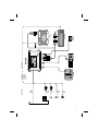
Electrical connections, Fig. 2
☞
Route all wiring with care. For wiring details, refer to the connection diagram on the back
cover page and to the following table.
☞
Do not cut non-assigned wires. Instead, wind them together and secure to one side. They
may be required for retrofitting additional functions.
Power supply cable
Wire colour Connection
Yellow + 12 V permanent positive (must be rated for at least 3.15 A.)
Red + 12 V ignition positive (without switch-off on starting engine)
Black Battery negative (body)
Blue/white + 12 V remote control input (activates the audio / video input)
Green + 12 V reversing signal (reversing light positive), active at + 12 V (active high)
Grey + 12 V parking brake signal, active at earth potential (active low)
A
Only connect electrical signals to suitable connecting points in the vehicle.
A
For direct connection of permanent positive (yellow lead) to the battery, the fuse must be no
further than 10 - 15 cm from the positive terminal of the battery. If it is necessary to extend the
positive lead, an additional 10 A fuse must be provided close to the battery (max. distance 10 -
15 cm). Failure to do so may result in a wiring fire hazard.
■
12 V permanent positive (yellow):
☞
Connect yellow wire to a suitable connector with 12 V permanent positive.
A
This connection should be rated for a current of at least 3.15 amps.
■
12 V ignition positive (red):
☞
Connect red wire to a suitable 12 V circuit switched through the ignition.
■
Battery negative (black)
☞
Connect black wire to a suitable earthing point on the vehicle body.
■
12 V remote control input (blue / white):
☞
Connect blue / white wire to 12 V remote control output of the connected video source.
In order to ensure full functionality of the MI 2100, the external video source should be pro
-
vided with a 12 V remote control output.
■
Reversing signal (green)
☞
Connect green wire to a suitable reversing signal point (positive lead of reversing light).
■
Parking brake signal (grey)
☞
Connect grey wire to a suitable parking brake signal point.
If the MI 2100 is used for the rear passengers, the grey wire should be permanently connect-
ed to earth.
INSTALLATION INSTRUCTIONS
English
7

Audio / video input “L – R – Video”
Any video source with composite video output and analogue stereo output can be connect-
ed to the MI 2100. The MI 2100 switches through video signals of all video standards. Please
ensure that the connected monitor is capable of displaying the television standard of the
relevant video source.
☞
Connect the video output of the video source to the yellow RCA/Cinch socket of the
MI 2100.
☞
Connect the audio output to the red (right channel) or white (left channel) RCA/Cinch
socket of the MI 2100.
Reversing camera “Camera”
Connect the VDO Dayton reversing camera to this input.
Monitor “Monitor”
Connect the VDO Dayton monitor MM 5000 or MM 5500 to this output.
Navigation computer “Navigation”
Connect the VDO Dayton navigation computer PC 5000 or PC 5100 to this input.
Install MI 2100
A
Do not install the unit in positions where it is exposed to high temperatures, dust, dirt or
excessive vibration (e.g. due to direct sunlight or heating vents).
Select installation location
The MI 2100 multimedia interface should be installed in a location, at which the “Stand-by”
switch and the volume control for the AUX input remain accessible, even after installation.
A
The MI 2100 must on no account be installed in the following locations:
❏
Directly below the heated rear window or other heated screens.
❏
Near to electric motors or other aggregates of the vehicle electrical system.
❏
Near to wiring harnesses of the vehicle electrical / electronic system.
❏
At locations, where it is exposed to high temperatures or direct sunlight.
❏
At locations with excessive humidity, spraying water or dirt.
When selecting the installation location, accessibility of the audio / video input for subse
-
quent retrofitting or conversion should also be taken into account.
Installation
The MI 2100 can be secured in a suitable installation location, using the screws supplied with
the unit. For this purpose, four fastening tabs are provided on the MI 2100 housing.
INSTALLATION INSTRUCTIONS
8

Initial operation and system check
1. Reconnect the battery.
2. Restore perfect functioning of the electrical system (clock, trip computer, alarm system, air
-
bag, immobiliser, radio coding etc.).
3. Switch on the ignition.
4. Switch “Stand-by” switch to “On” position. The monitor is switched on. If a navigation
computer is connected, ensure that this is not in stand-by mode.
5. Engage reverse gear. The reversing camera image must appear on the monitor with the
parking brake released as well as applied.
6. Select neutral or, for automatic transmissions, position “P”. If a navigation system is
connected, the navigation image must now appear on the monitor. Ensure that the
navigation system is not in stand-by mode.
7. Navigation system and external video source connected:
Apply the parking brake. Switch on external video source. In the Start menu of the
navigation system, select the option “Stand-by”. The image of the external video source
must appear on the monitor. The sound of the video source must be heard from the
monitor loudspeaker.
8. No navigation system connected:
Apply the parking brake. Switch on external video source. The image and sound of the
external video source must be produced by the monitor.
Volume adaptation
Volume adaptation between audio / video input and the navigation system can be
performed via the MI 2100 volume control, using a screwdriver.
Checking the vehicle functions
A
Check the safety-relevant vehicle functions only when the car is stationary, or moving at low
speed. Only perform the check in an open area.
Brake system, alarm system, lighting system, immobiliser, speedometer, trip computer, radio
(coding) and hi-fi system, clock.
Hotline
If you have any questions about VDO Dayton Multimedia, a hotline is available in many
countries: The phone number for your country can be found on a separate loose leaf.
INSTALLATION INSTRUCTIONS
English
9

MI 2100
MI 2100 07/2002 ri
English
Français
Deutsch
Nederlands
Italiano
Español
Dansk
Owner’s manual and mounting instruction
Mode d’emploi et manuel d’installation
Bedienungs- und Einbauanleitung
Gebruiksaanwijzing en inbouwhandleiding
Istruzioni d’uso e d’installazione
Instrucciones de manejo y de montaje
Betjeningsvejledning og monteringsanvisning
Owner’s manual and mounting instruction
Mode d’emploi et manuel d’installation
Bedienungs- und Einbauanleitung
Gebruiksaanwijzing en inbouwhandleiding
Istruzioni d’uso e d’installazione
Instrucciones de manejo y de montaje
Betjeningsvejledning og monteringsanvisning
-
 1
1
-
 2
2
-
 3
3
-
 4
4
-
 5
5
-
 6
6
-
 7
7
-
 8
8
-
 9
9


dans d''autres langues
- English: VDO MI 2100 Owner's manual
Documents connexes
-
VDO MI 2200 Le manuel du propriétaire
-
-
-
-
-
-
